The attributes below are the
transfer function element
attributes, which apply to the transfer function elements.
Attribute definitions:
- type
= "identity | table | discrete | linear | gamma"
-
Indicates the type of component transfer function. The type of
function determines the applicability of the other attributes.
In the following, C is the initial component (e.g., <feFuncR>), C' is the remapped
component; both in the closed interval [0,1].
- For ‘
identity’:
C' = C
- For ‘
table’, the function is defined
by linear interpolation between values given in the attribute ‘tableValues’. The table has
n+1 values (i.e., v0 to vn)
specifying the start and end values for n evenly sized
interpolation regions. Interpolations use the following formula:
For a value C < 1 find k such
that:
k/n <= C < (k+1)/n
The result C' is given by:
C' = vk + (C - k/n)*n *
(vk+1 - vk)
If C = 1 then:
C' = vn.
- For ‘
discrete’, the function is
defined by the step function given in the attribute ‘tableValues’, which provides a list of
n values (i.e., v0 to vn-1) in
order to identify a step function consisting of n steps.
The step function is defined by the following formula:
For a value C < 1 find k such
that:
k/n <= C < (k+1)/n
The result C' is given by:
C' = vk
If C = 1 then:
C' = vn-1.
- For ‘
linear’, the function is
defined by the following linear equation:
C' = slope * C + intercept
- For ‘
gamma’, the function is defined
by the following exponential function:
C' = amplitude * pow(C, exponent) + offset
Animatable: yes.
- tableValues = "(list of <number>s)"
- When type="table", the list of <number>
s v0,v1,...vn, separated by white space and/or a comma,
which define the lookup table. An empty list results in an identity
transfer function. If the attribute is not specified, then the
effect is as if an empty list were provided.
Animatable: yes.
- slope = "<number>"
- When type="linear", the slope of
the linear function.
The lacuna
value for ‘slope’ is 1.
Animatable: yes.
- intercept = "<number>"
- When type="linear", the intercept
of the linear function.
The lacuna
value for ‘intercept’ is 0.
Animatable: yes.
- amplitude = "<number>"
- When type="gamma", the amplitude of
the gamma function.
The lacuna
value for ‘amplitude’ is 1.
Animatable: yes.
- exponent = "<number>"
- When type="gamma", the exponent of
the gamma function.
The lacuna
value for ‘exponent’ is 1.
Animatable: yes.
- offset = "<number>"
- When type="gamma", the offset of
the gamma function.
The lacuna
value for ‘offset’ is 0.
Animatable: yes.
<?xml version="1.0"?>
<!DOCTYPE svg PUBLIC "-//W3C//DTD SVG 1.1//EN"
          "http://www.w3.org/Graphics/SVG/1.1/DTD/svg11.dtd">
<svg width="8cm" height="4cm" viewBox="0 0 800 400"
     xmlns="http://www.w3.org/2000/svg" version="1.1">
  <title>Example feComponentTransfer - Examples of feComponentTransfer operations</title>
  <desc>Four text strings showing the effects of feComponentTransfer:
        an identity function acting as a reference,
        use of the feComponentTransfer table option,
        use of the feComponentTransfer linear option,
        and use of the feComponentTransfer gamma option.</desc>
  <defs>
    <linearGradient id="MyGradient" gradientUnits="userSpaceOnUse"
            x1="100" y1="0" x2="600" y2="0">
      <stop offset="0" stop-color="#ff0000" />
      <stop offset=".33" stop-color="#00ff00" />
      <stop offset=".67" stop-color="#0000ff" />
      <stop offset="1" stop-color="#000000" />
    </linearGradient>
    <filter id="Identity" filterUnits="objectBoundingBox"
            x="0%" y="0%" width="100%" height="100%">
      <feComponentTransfer>
        <feFuncR type="identity"/>
        <feFuncG type="identity"/>
        <feFuncB type="identity"/>
        <feFuncA type="identity"/>
      </feComponentTransfer>
    </filter>
    <filter id="Table" filterUnits="objectBoundingBox"
            x="0%" y="0%" width="100%" height="100%">
      <feComponentTransfer>
        <feFuncR type="table" tableValues="0 0 1 1"/>
        <feFuncG type="table" tableValues="1 1 0 0"/>
        <feFuncB type="table" tableValues="0 1 1 0"/>
      </feComponentTransfer>
    </filter>
    <filter id="Linear" filterUnits="objectBoundingBox"
            x="0%" y="0%" width="100%" height="100%">
      <feComponentTransfer>
        <feFuncR type="linear" slope=".5" intercept=".25"/>
        <feFuncG type="linear" slope=".5" intercept="0"/>
        <feFuncB type="linear" slope=".5" intercept=".5"/>
      </feComponentTransfer>
    </filter>
    <filter id="Gamma" filterUnits="objectBoundingBox"
            x="0%" y="0%" width="100%" height="100%">
      <feComponentTransfer>
        <feFuncR type="gamma" amplitude="2" exponent="5" offset="0"/>
        <feFuncG type="gamma" amplitude="2" exponent="3" offset="0"/>
        <feFuncB type="gamma" amplitude="2" exponent="1" offset="0"/>
      </feComponentTransfer>
    </filter>
  </defs>
  <rect fill="none" stroke="blue"
        x="1" y="1" width="798" height="398"/>
  <g font-family="Verdana" font-size="75"
            font-weight="bold" fill="url(#MyGradient)" >
    <rect x="100" y="0" width="600" height="20" />
    <text x="100" y="90">Identity</text>
    <text x="100" y="190" filter="url(#Table)" >TableLookup</text>
    <text x="100" y="290" filter="url(#Linear)" >LinearFunc</text>
    <text x="100" y="390" filter="url(#Gamma)" >GammaFunc</text>
  </g>
</svg>
View
this example as SVG (SVG-enabled browsers only)
| Name:
| feComposite
|
| Categories:
| Filter primitive
element
|
| Content model:
| Any number of the following elements, in any order:
|
| Attributes:
|
- core
attributes — ‘id’, ‘xml:base’, ‘xml:lang’, ‘xml:space’
- presentation
attributes — ‘
alignment-baseline’, ‘baseline-shift’, ‘clip’, ‘clip-path’, ‘clip-rule’, ‘color’, ‘color-interpolation’, ‘color-interpolation-filters’, ‘color-profile’, ‘color-rendering’, ‘cursor’, ‘direction’, ‘display’, ‘dominant-baseline’, ‘enable-background’, ‘fill’, ‘fill-opacity’, ‘fill-rule’, ‘filter’, ‘flood-color’, ‘flood-opacity’, ‘font’, ‘font-family’, ‘font-size’, ‘font-size-adjust’, ‘font-stretch’, ‘font-style’, ‘font-variant’, ‘font-weight’, ‘glyph-orientation-horizontal’, ‘glyph-orientation-vertical’, ‘image-rendering’, ‘kerning’, ‘letter-spacing’, ‘lighting-color’, ‘marker’, ‘marker-end’, ‘marker-mid’, ‘marker-start’, ‘mask’, ‘mix-blend-mode’, ‘opacity’, ‘overflow’, ‘pointer-events’, ‘shape-rendering’, ‘stop-color’, ‘stop-opacity’, ‘stroke’, ‘stroke-dasharray’, ‘stroke-dashoffset’, ‘stroke-linecap’, ‘stroke-linejoin’, ‘stroke-miterlimit’, ‘stroke-opacity’, ‘stroke-width’, ‘text-anchor’, ‘text-decoration’, ‘text-rendering’, ‘unicode-bidi’, ‘visibility’, ‘word-spacing’, ‘writing-mode’
- filter primitive
attributes — ‘x’, ‘y’, ‘width’, ‘height’, ‘result’
- ‘class’
- ‘style’
- ‘in’
- ‘in2’
- ‘operator’
- ‘k1’
- ‘k2’
- ‘k3’
- ‘k4’
|
| DOM Interfaces:
| SVGFECompositeElement
|
This filter performs the combination of the two input images
pixel-wise in image space using one of the Porter-Duff [PORTERDUFF] compositing operations:
over, in, atop, out, xor [COMPOSITING].
Additionally, a component-wise arithmetic operation (with the
result clamped between [0..1]) can be applied.
The arithmetic operation is useful for combining the
output from the <feDiffuseLighting> and <feSpecularLighting> filters with
texture data. It is also useful for implementing dissolve. If
the arithmetic operation is chosen, each result pixel is
computed using the following formula:
result = k1*i1*i2 + k2*i1 + k3*i2 + k4
where:
-
i1 and i2 indicate the corresponding
pixel channel values of the input image, which map to ‘in’ and ‘in2’
respectively
-
k1, k2, k3 and k4 indicate the values
of the attributes with the same name
For this filter primitive, the extent of the resulting image might
grow as described in the section that describes the filter primitive subregion.
Attribute definitions:
- operator
= "over | in | out | atop | xor | arithmetic"
- The compositing operation that is to be performed. All of the
operator types except arithmetic match the corresponding operation
as described in [PORTERDUFF]. The
arithmetic operator is described
above. The lacuna
value for ‘
operator’ is over.
Animatable: yes.
- k1 = "<number>"
- Only applicable if operator="arithmetic".
The lacuna
value for ‘k1’
is 0.
Animatable: yes.
- k2 = "<number>"
- Only applicable if operator="arithmetic".
The lacuna
value for ‘k2’
is 0.
Animatable: yes.
- k3 = "<number>"
- Only applicable if operator="arithmetic".
The lacuna
value for ‘k3’
is 0.
Animatable: yes.
- k4 = "<number>"
- Only applicable if operator="arithmetic".
The lacuna
value for ‘k4’
is 0.
Animatable: yes.
- in2 =
"(see in attribute)"
- The second input image to the compositing operation. This
attribute can take on the same values as the in attribute.
Animatable: yes.
<?xml version="1.0"?>
<!DOCTYPE svg PUBLIC "-//W3C//DTD SVG 1.1//EN"
          "http://www.w3.org/Graphics/SVG/1.1/DTD/svg11.dtd">
<svg width="330" height="195" viewBox="0 0 1100 650" version="1.1"
     xmlns="http://www.w3.org/2000/svg" xmlns:xlink="http://www.w3.org/1999/xlink">
  <title>Example feComposite - Examples of feComposite operations</title>
  <desc>Four rows of six pairs of overlapping triangles depicting
        the six different feComposite operators under different
        opacity values and different clearing of the background.</desc>
  <defs>
    <desc>Define two sets of six filters for each of the six compositing operators.
          The first set wipes out the background image by flooding with opaque white.
          The second set does not wipe out the background, with the result
          that the background sometimes shines through and is other cases
          is blended into itself (i.e., "double-counting").</desc>
    <filter id="overFlood" filterUnits="objectBoundingBox" x="-5%" y="-5%" width="110%" height="110%">
      <feFlood flood-color="#ffffff" flood-opacity="1" result="flood"/>
      <feComposite in="SourceGraphic" in2="BackgroundImage" operator="over" result="comp"/>
      <feMerge> <feMergeNode in="flood"/> <feMergeNode in="comp"/> </feMerge>
    </filter>
    <filter id="inFlood" filterUnits="objectBoundingBox" x="-5%" y="-5%" width="110%" height="110%">
      <feFlood flood-color="#ffffff" flood-opacity="1" result="flood"/>
      <feComposite in="SourceGraphic" in2="BackgroundImage" operator="in" result="comp"/>
      <feMerge> <feMergeNode in="flood"/> <feMergeNode in="comp"/> </feMerge>
    </filter>
    <filter id="outFlood" filterUnits="objectBoundingBox" x="-5%" y="-5%" width="110%" height="110%">
      <feFlood flood-color="#ffffff" flood-opacity="1" result="flood"/>
      <feComposite in="SourceGraphic" in2="BackgroundImage" operator="out" result="comp"/>
      <feMerge> <feMergeNode in="flood"/> <feMergeNode in="comp"/> </feMerge>
    </filter>
    <filter id="atopFlood" filterUnits="objectBoundingBox" x="-5%" y="-5%" width="110%" height="110%">
      <feFlood flood-color="#ffffff" flood-opacity="1" result="flood"/>
      <feComposite in="SourceGraphic" in2="BackgroundImage" operator="atop" result="comp"/>
      <feMerge> <feMergeNode in="flood"/> <feMergeNode in="comp"/> </feMerge>
    </filter>
    <filter id="xorFlood" filterUnits="objectBoundingBox" x="-5%" y="-5%" width="110%" height="110%">
      <feFlood flood-color="#ffffff" flood-opacity="1" result="flood"/>
      <feComposite in="SourceGraphic" in2="BackgroundImage" operator="xor" result="comp"/>
      <feMerge> <feMergeNode in="flood"/> <feMergeNode in="comp"/> </feMerge>
    </filter>
    <filter id="arithmeticFlood" filterUnits="objectBoundingBox"
            x="-5%" y="-5%" width="110%" height="110%">
      <feFlood flood-color="#ffffff" flood-opacity="1" result="flood"/>
      <feComposite in="SourceGraphic" in2="BackgroundImage" result="comp"
                   operator="arithmetic" k1=".5" k2=".5" k3=".5" k4=".5"/>
      <feMerge> <feMergeNode in="flood"/> <feMergeNode in="comp"/> </feMerge>
    </filter>
    <filter id="overNoFlood" filterUnits="objectBoundingBox" x="-5%" y="-5%" width="110%" height="110%">
      <feComposite in="SourceGraphic" in2="BackgroundImage" operator="over" result="comp"/>
    </filter>
    <filter id="inNoFlood" filterUnits="objectBoundingBox" x="-5%" y="-5%" width="110%" height="110%">
      <feComposite in="SourceGraphic" in2="BackgroundImage" operator="in" result="comp"/>
    </filter>
    <filter id="outNoFlood" filterUnits="objectBoundingBox" x="-5%" y="-5%" width="110%" height="110%">
      <feComposite in="SourceGraphic" in2="BackgroundImage" operator="out" result="comp"/>
    </filter>
    <filter id="atopNoFlood" filterUnits="objectBoundingBox" x="-5%" y="-5%" width="110%" height="110%">
      <feComposite in="SourceGraphic" in2="BackgroundImage" operator="atop" result="comp"/>
    </filter>
    <filter id="xorNoFlood" filterUnits="objectBoundingBox" x="-5%" y="-5%" width="110%" height="110%">
      <feComposite in="SourceGraphic" in2="BackgroundImage" operator="xor" result="comp"/>
    </filter>
    <filter id="arithmeticNoFlood" filterUnits="objectBoundingBox"
            x="-5%" y="-5%" width="110%" height="110%">
      <feComposite in="SourceGraphic" in2="BackgroundImage" result="comp"
                   operator="arithmetic" k1=".5" k2=".5" k3=".5" k4=".5"/>
    </filter>
    <path id="Blue100" d="M 0 0 L 100 0 L 100 100 z" fill="#00ffff" />
    <path id="Red100" d="M 0 0 L 0 100 L 100 0 z" fill="#ff00ff" />
    <path id="Blue50" d="M 0 125 L 100 125 L 100 225 z" fill="#00ffff" fill-opacity=".5" />
    <path id="Red50" d="M 0 125 L 0 225 L 100 125 z" fill="#ff00ff" fill-opacity=".5" />
    <g id="TwoBlueTriangles">
      <use xlink:href="#Blue100"/>
      <use xlink:href="#Blue50"/>
    </g>
    <g id="BlueTriangles">
      <use transform="translate(275,25)" xlink:href="#TwoBlueTriangles"/>
      <use transform="translate(400,25)" xlink:href="#TwoBlueTriangles"/>
      <use transform="translate(525,25)" xlink:href="#TwoBlueTriangles"/>
      <use transform="translate(650,25)" xlink:href="#TwoBlueTriangles"/>
      <use transform="translate(775,25)" xlink:href="#TwoBlueTriangles"/>
      <use transform="translate(900,25)" xlink:href="#TwoBlueTriangles"/>
    </g>
  </defs>

  <rect fill="none" stroke="blue" x="1" y="1" width="1098" height="648"/>
  <g font-family="Verdana" font-size="40" shape-rendering="crispEdges">
    <desc>Render the examples using the filters that draw on top of
          an opaque white surface, thus obliterating the background.</desc>
    <g enable-background="new">
      <text x="15" y="75">opacity 1.0</text>
      <text x="15" y="115" font-size="27">(with feFlood)</text>
      <text x="15" y="200">opacity 0.5</text>
      <text x="15" y="240" font-size="27">(with feFlood)</text>
      <use xlink:href="#BlueTriangles"/>
      <g transform="translate(275,25)">
        <use xlink:href="#Red100" filter="url(#overFlood)" />
        <use xlink:href="#Red50" filter="url(#overFlood)" />
        <text x="5" y="275">over</text>
      </g>
      <g transform="translate(400,25)">
        <use xlink:href="#Red100" filter="url(#inFlood)" />
        <use xlink:href="#Red50" filter="url(#inFlood)" />
        <text x="35" y="275">in</text>
      </g>
      <g transform="translate(525,25)">
        <use xlink:href="#Red100" filter="url(#outFlood)" />
        <use xlink:href="#Red50" filter="url(#outFlood)" />
        <text x="15" y="275">out</text>
      </g>
      <g transform="translate(650,25)">
        <use xlink:href="#Red100" filter="url(#atopFlood)" />
        <use xlink:href="#Red50" filter="url(#atopFlood)" />
        <text x="10" y="275">atop</text>
      </g>
      <g transform="translate(775,25)">
        <use xlink:href="#Red100" filter="url(#xorFlood)" />
        <use xlink:href="#Red50" filter="url(#xorFlood)" />
        <text x="15" y="275">xor</text>
      </g>
      <g transform="translate(900,25)">
        <use xlink:href="#Red100" filter="url(#arithmeticFlood)" />
        <use xlink:href="#Red50" filter="url(#arithmeticFlood)" />
        <text x="-25" y="275">arithmetic</text>
      </g>
    </g>
    <g transform="translate(0,325)" enable-background="new">
    <desc>Render the examples using the filters that do not obliterate
          the background, thus sometimes causing the background to continue
          to appear in some cases, and in other cases the background
          image blends into itself ("double-counting").</desc>
      <text x="15" y="75">opacity 1.0</text>
      <text x="15" y="115" font-size="27">(without feFlood)</text>
      <text x="15" y="200">opacity 0.5</text>
      <text x="15" y="240" font-size="27">(without feFlood)</text>
      <use xlink:href="#BlueTriangles"/>
      <g transform="translate(275,25)">
        <use xlink:href="#Red100" filter="url(#overNoFlood)" />
        <use xlink:href="#Red50" filter="url(#overNoFlood)" />
        <text x="5" y="275">over</text>
      </g>
      <g transform="translate(400,25)">
        <use xlink:href="#Red100" filter="url(#inNoFlood)" />
        <use xlink:href="#Red50" filter="url(#inNoFlood)" />
        <text x="35" y="275">in</text>
      </g>
      <g transform="translate(525,25)">
        <use xlink:href="#Red100" filter="url(#outNoFlood)" />
        <use xlink:href="#Red50" filter="url(#outNoFlood)" />
        <text x="15" y="275">out</text>
      </g>
      <g transform="translate(650,25)">
        <use xlink:href="#Red100" filter="url(#atopNoFlood)" />
        <use xlink:href="#Red50" filter="url(#atopNoFlood)" />
        <text x="10" y="275">atop</text>
      </g>
      <g transform="translate(775,25)">
        <use xlink:href="#Red100" filter="url(#xorNoFlood)" />
        <use xlink:href="#Red50" filter="url(#xorNoFlood)" />
        <text x="15" y="275">xor</text>
      </g>
      <g transform="translate(900,25)">
        <use xlink:href="#Red100" filter="url(#arithmeticNoFlood)" />
        <use xlink:href="#Red50" filter="url(#arithmeticNoFlood)" />
        <text x="-25" y="275">arithmetic</text>
      </g>
    </g>
  </g>
</svg>
View this
example as SVG (SVG-enabled browsers only)
| Name:
| feConvolveMatrix
|
| Categories:
| Filter primitive
element
|
| Content model:
| Any number of the following elements, in any order:
|
| Attributes:
|
- core
attributes — ‘id’, ‘xml:base’, ‘xml:lang’, ‘xml:space’
- presentation
attributes — ‘
alignment-baseline’, ‘baseline-shift’, ‘clip’, ‘clip-path’, ‘clip-rule’, ‘color’, ‘color-interpolation’, ‘color-interpolation-filters’, ‘color-profile’, ‘color-rendering’, ‘cursor’, ‘direction’, ‘display’, ‘dominant-baseline’, ‘enable-background’, ‘fill’, ‘fill-opacity’, ‘fill-rule’, ‘filter’, ‘flood-color’, ‘flood-opacity’, ‘font’, ‘font-family’, ‘font-size’, ‘font-size-adjust’, ‘font-stretch’, ‘font-style’, ‘font-variant’, ‘font-weight’, ‘glyph-orientation-horizontal’, ‘glyph-orientation-vertical’, ‘image-rendering’, ‘kerning’, ‘letter-spacing’, ‘lighting-color’, ‘marker’, ‘marker-end’, ‘marker-mid’, ‘marker-start’, ‘mask’, ‘mix-blend-mode’, ‘opacity’, ‘overflow’, ‘pointer-events’, ‘shape-rendering’, ‘stop-color’, ‘stop-opacity’, ‘stroke’, ‘stroke-dasharray’, ‘stroke-dashoffset’, ‘stroke-linecap’, ‘stroke-linejoin’, ‘stroke-miterlimit’, ‘stroke-opacity’, ‘stroke-width’, ‘text-anchor’, ‘text-decoration’, ‘text-rendering’, ‘unicode-bidi’, ‘visibility’, ‘word-spacing’, ‘writing-mode’
- filter primitive
attributes — ‘x’, ‘y’, ‘width’, ‘height’, ‘result’
- ‘class’
- ‘style’
- ‘in’
- ‘order’
- ‘kernelMatrix’
- ‘divisor’
- ‘bias’
- ‘targetX’
- ‘targetY’
- ‘edgeMode’
- ‘kernelUnitLength’
- ‘preserveAlpha’
|
| DOM Interfaces:
| SVGFEConvolveMatrixElement
|
feConvolveMatrix applies a matrix convolution filter effect. A
convolution combines pixels in the input image with neighboring pixels
to produce a resulting image. A wide variety of imaging operations can
be achieved through convolutions, including blurring, edge detection,
sharpening, embossing and beveling.
A matrix convolution is based on an n-by-m matrix (the convolution
kernel) which describes how a given pixel value in the input image is
combined with its neighboring pixel values to produce a resulting
pixel value. Each result pixel is determined by applying the kernel
matrix to the corresponding source pixel and its neighboring pixels.
The basic convolution formula which is applied to each color value for
a given pixel is:
where "orderX" and "orderY" represent the X and Y values for the ‘order’ attribute, "targetX" represents the
value of the ‘targetX’ attribute, "targetY" represents
the value of the ‘targetY’ attribute, "kernelMatrix"
represents the value of the ‘kernelMatrix’ attribute, "divisor"
represents the value of the ‘divisor’ attribute, and "bias" represents
the value of the ‘bias’ attribute.
Note in the above formulas that the values in the kernel matrix are
applied such that the kernel matrix is rotated 180 degrees relative to
the source and destination images in order to match convolution theory
as described in many computer graphics textbooks.
To illustrate, suppose you have a input image which is 5 pixels by
5 pixels, whose color values for one of the color channels are as
follows:
and you define a 3-by-3 convolution kernel as follows:
Let's focus on the color value at the second row and second column
of the image (source pixel value is 120). Assuming the simplest case
(where the input image's pixel grid aligns perfectly with the kernel's
pixel grid) and assuming default values for attributes ‘divisor’, ‘targetX’ and ‘targetY’, then resulting color value will
be:
Because they operate on pixels, matrix convolutions are inherently
resolution-dependent. To make <feConvolveMatrix> produce
resolution-independent results, an explicit value should be provided
for either the ‘filterRes’ attribute on the <filter>
element and/or attribute ‘kernelUnitLength’.
‘kernelUnitLength’, in combination with the
other attributes, defines an implicit pixel grid in the filter effects
coordinate system (i.e., the coordinate system established by the ‘primitiveUnits’ attribute). If the pixel
grid established by ‘kernelUnitLength’ is not scaled to match
the pixel grid established by attribute ‘filterRes’ (implicitly or explicitly),
then the input image will be temporarily rescaled to match its pixels
with ‘kernelUnitLength’. The convolution happens
on the resampled image. After applying the convolution, the image is
resampled back to the original resolution.
When the image must be resampled to match the coordinate system
defined by ‘kernelUnitLength’ prior to convolution, or
resampled to match the device coordinate system after convolution, it
is recommended that high quality viewers make use of appropriate
interpolation techniques, for example bilinear or bicubic. Depending
on the speed of the available interpolents, this choice may be
affected by the ‘image-rendering’ property setting. Note
that implementations might choose approaches that minimize or
eliminate resampling when not necessary to produce proper results,
such as when the document is zoomed out such that ‘kernelUnitLength’ is considerably smaller
than a device pixel.
Attribute definitions:
- order = "<number-optional-number>"
- Indicates the number of cells in each dimension for ‘
kernelMatrix’. The values provided must
be <integer>
s greater than zero. Values that are not integers will be truncated,
i.e. rounded to the closest integer value towards zero. The first
number, <orderX>, indicates the number of columns in the
matrix. The second number, <orderY>, indicates the number of
rows in the matrix. If <orderY> is not provided, it defaults
to <orderX>.
It is recommended that only small values (e.g., 3) be used; higher
values may result in very high CPU overhead and usually do not
produce results that justify the impact on performance.
The lacuna
value for ‘order’ is 3.
Animatable: yes.
- kernelMatrix = "<list of
numbers>"
- The list of <number>
s that make up the kernel matrix for the convolution. Values are
separated by space characters and/or a comma. The number of entries
in the list must equal <orderX> times <orderY>.
Animatable: yes.
- divisor = "<number>"
- After applying the kernelMatrix to
the input image to yield a number, that number is divided by ‘
divisor’ to yield the final destination
color value. A divisor that is the sum of all the matrix values
tends to have an evening effect on the overall color intensity of
the result. If the specified divisor is zero then the default value
will be used instead. The lacuna
value is the sum of all values in kernelMatrix, with the
exception that if the sum is zero, then the divisor is set to 1.
Animatable: yes.
- bias = "<number>"
- After applying the kernelMatrix to
the input image to yield a number and applying the ‘
divisor’, the ‘bias’ attribute is added to each
component. One application of ‘bias’ is when it is desirable to have
.5 gray value be the zero response of
the filter. The bias property shifts the range of the filter. This
allows representation of values that would otherwise be clamped to 0
or 1.
The lacuna
value for ‘bias’ is 0.
Animatable: yes.
- targetX = "<integer>"
- Determines the positioning in X of the convolution matrix
relative to a given target pixel in the input image. The leftmost
column of the matrix is column number zero. The value must be such
that: 0 <= targetX < orderX. By default, the convolution
matrix is centered in X over each pixel of the input image (i.e.,
targetX = floor ( orderX / 2 )).
Animatable: yes.
- targetY = "<integer>"
- Determines the positioning in Y of the convolution matrix
relative to a given target pixel in the input image. The topmost row
of the matrix is row number zero. The value must be such that: 0
<= targetY < orderY. By default, the convolution matrix is
centered in Y over each pixel of the input image (i.e., targetY =
floor ( orderY / 2 )).
Animatable: yes.
- edgeMode = "duplicate |
wrap | none"
-
Determines how to extend the input image as necessary with color
values so that the matrix operations can be applied when the kernel
is positioned at or near the edge of the input image.
"duplicate" indicates that the input image is extended along each
of its borders as necessary by duplicating the color values at the
given edge of the input image.
Original N-by-M image, where m=M-1 and n=N-1:
Extended by two pixels using "duplicate":
"wrap" indicates that the input image is extended by taking the
color values from the opposite edge of the image.
Extended by two pixels using "wrap":
The value none indicates that the
input image is extended with pixel values of zero for R, G, B and
A.
The lacuna
value for ‘edgeMode’ is duplicate.
Animatable: yes.
- kernelUnitLength = "<number-optional-number>"
- The first number is the <dx> value. The second number is
the <dy> value. If the <dy> value is not specified, it
defaults to the same value as <dx>. Indicates the intended
distance in current filter units (i.e., units as determined by the
value of attribute ‘
primitiveUnits’) between successive
columns and rows, respectively, in the ‘kernelMatrix’. By specifying value(s)
for ‘kernelUnitLength’, the kernel becomes
defined in a scalable, abstract coordinate system. If ‘kernelUnitLength’ is not specified, the
default value is one pixel in the offscreen bitmap, which is a
pixel-based coordinate system, and thus potentially not scalable.
For some level of consistency across display media and user agents,
it is necessary that a value be provided for at least one of ‘filterRes’ and ‘kernelUnitLength’. In some
implementations, the most consistent results and the fastest
performance will be achieved if the pixel grid of the temporary
offscreen images aligns with the pixel grid of the kernel.
If a negative or zero value is specified the default value will be
used instead.
Animatable: yes.
- preserveAlpha = "false |
true"
- A value of false indicates that the
convolution will apply to all channels, including the alpha channel.
In this case the
ALPHAX,Y of the convolution formula for a
given pixel is:
ALPHAX,Y = (
SUM I=0 to [‘orderY’-1] {
SUM J=0 to [‘orderX’-1] {
SOURCE X-‘targetX’+J, Y-‘targetY’+I * ‘kernelMatrix’‘orderX’-J-1, ‘orderY’-I-1
}
}
) / ‘divisor’ + ‘bias’
A value of true indicates that the
convolution will only apply to the color channels. In this case, the
filter will temporarily unpremultiply the color component values,
apply the kernel, and then re-premultiply at the end. In this case
the ALPHAX,Y of the convolution formula for a
given pixel is:
ALPHAX,Y = SOURCEX,Y
The lacuna
value for ‘preserveAlpha’ is false.
Animatable: yes.
8.9. Filter primitive
<feCustom>
| Name:
| feCustom
|
| Categories:
| Filter primitive
element
|
| Content model:
| Any number of the following elements, in any order:
|
| Attributes:
|
- core
attributes — ‘id’, ‘xml:base’, ‘xml:lang’, ‘xml:space’
- presentation
attributes — ‘
alignment-baseline’, ‘baseline-shift’, ‘clip’, ‘clip-path’, ‘clip-rule’, ‘color’, ‘color-interpolation’, ‘color-interpolation-filters’, ‘color-profile’, ‘color-rendering’, ‘cursor’, ‘direction’, ‘display’, ‘dominant-baseline’, ‘enable-background’, ‘fill’, ‘fill-opacity’, ‘fill-rule’, ‘filter’, ‘flood-color’, ‘flood-opacity’, ‘font’, ‘font-family’, ‘font-size’, ‘font-size-adjust’, ‘font-stretch’, ‘font-style’, ‘font-variant’, ‘font-weight’, ‘glyph-orientation-horizontal’, ‘glyph-orientation-vertical’, ‘image-rendering’, ‘kerning’, ‘letter-spacing’, ‘lighting-color’, ‘marker’, ‘marker-end’, ‘marker-mid’, ‘marker-start’, ‘mask’, ‘mix-blend-mode’, ‘opacity’, ‘overflow’, ‘pointer-events’, ‘shape-rendering’, ‘stop-color’, ‘stop-opacity’, ‘stroke’, ‘stroke-dasharray’, ‘stroke-dashoffset’, ‘stroke-linecap’, ‘stroke-linejoin’, ‘stroke-miterlimit’, ‘stroke-opacity’, ‘stroke-width’, ‘text-anchor’, ‘text-decoration’, ‘text-rendering’, ‘unicode-bidi’, ‘visibility’, ‘word-spacing’, ‘writing-mode’
- filter primitive
attributes — ‘x’, ‘y’, ‘width’, ‘height’, ‘result’
- ‘class’
- ‘style’
- ‘geometry’
|
| DOM Interfaces:
| SVGFECustomElement
|
Attribute definitions:
- geometry = "grid(<integer>{0,2} [
detached | attached ]?"
- See the ‘
geometry’ descriptor.
Animatable: yes.
The calculations are performed on non-premultiplied color values.
If the input graphics consists of premultiplied color values, those
values are converted into non-premultiplied color values for this
operation.
Each ‘feCustom’ element can have any number of
‘feCustomSource’ subelements. Each ‘feCustomSource’ references one resource.
| Name:
| feCustomSource
|
| Categories:
| None.
|
| Content model:
| Any number of the following elements, in any order:
|
| Attributes:
|
|
| DOM Interfaces:
| SVGFECustomSourceElement
|
Attribute definitions:
- src
= "<string>"
- An Functional IRI reference to an
resource which defines the custom filter.
Animatable: yes.
- format
= "<string>"
- The format of the resource referenced by the ‘
src’ attribute.
Animatable: yes.
Each ‘feCustom’ element can have any number of
‘feCustomParam’ subelements. Each ‘feCustomParam’
node passes one parameter.
| Name:
| feCustomParam
|
| Categories:
| None.
|
| Content model:
| Any number of the following elements, in any order:
|
| Attributes:
|
|
| DOM Interfaces:
| SVGFECustomParamElement
|
Attribute definitions:
- ident =
"<string>"
- Indicates the parameter name to the shaders.
Animatable: yes.
- type =
"number | array | vec2 | vec3 | vec4 | mat2 | mat3 | mat4 |
color | image | transform"
- Indicates the type of the parameter passed to the shaders. For
the types ‘
number’, ‘array’, ‘vec2’,
‘vec3’, ‘vec4’, ‘mat2’,
‘mat3’ and ‘mat4’, the ‘values’ attribute passes the values to
the shader. For all other types, the attributes with the same name
pass the parameter to the shader. The lacuna
value for ‘type’ is number.
Animatable: yes.
- values =
"list of <number>s"
- The contents of values depends on
the value of attribute type:
- For type="number", values is a single real number value.
- For type="array", values is a list of at least one real
number value.
- For type="vec2", values is a list of two real number values.
The value list is interpreted as a vertical list, where the first
entry equals the parameter on the top of the vector.
- For type="vec3", values is a list of three real number
values. The value list is interpreted as a vertical list, where
the first entry equals the parameter on the top of the vector.
- For type="vec4", values is a list of four real number
values. The value list is interpreted as a vertical list, where
the first entry equals the parameter on the top of the vector.
- For type="mat2", values is a list of four real number
values. The list specifies a 2x2 homogeneous matrix in
column-major order.
- For type="mat3", values is a list of nine real number
values. The list specifies a 3x3 homogeneous matrix in
column-major order.
- For type="mat4", values is a list of 16 real number values.
The list specifies a 4x4 homogeneous matrix in column-major order.
If the attribute is not specified, then the default behavior
depends on the value of attribute type. If type
is ‘mat2’, ‘mat3’ or ‘mat4’, then
this attribute defaults to the identity matrix. If type is ‘number’
or ‘array’, then this attribute defaults
to the value 0. If type is ‘vec2’, ‘vec3’ or
‘vec4’, then this attribute defaults to
a number list with values of 0. The length of the number list
depends on the size of the specified vector.
Animatable: yes.
- color =
"<color>"
- Indicates that a color value is passed as parameter to the
shaders.
Animatable: yes.
- image =
"<URI>"
- Indicates that a image is passed as parameter to the shaders.
Animatable: yes.
- transform = "<transform-list>"
- Indicates that a list of transform functions is passed as
parameter to the shaders.
Animatable: yes.
| Name:
| feDiffuseLighting
|
| Categories:
| Filter primitive
element
|
| Content model:
| Any number of descriptive
elements and exactly one light source element, in any
order.
|
| Attributes:
|
- core
attributes — ‘id’, ‘xml:base’, ‘xml:lang’, ‘xml:space’
- presentation
attributes — ‘
alignment-baseline’, ‘baseline-shift’, ‘clip’, ‘clip-path’, ‘clip-rule’, ‘color’, ‘color-interpolation’, ‘color-interpolation-filters’, ‘color-profile’, ‘color-rendering’, ‘cursor’, ‘direction’, ‘display’, ‘dominant-baseline’, ‘enable-background’, ‘fill’, ‘fill-opacity’, ‘fill-rule’, ‘filter’, ‘flood-color’, ‘flood-opacity’, ‘font’, ‘font-family’, ‘font-size’, ‘font-size-adjust’, ‘font-stretch’, ‘font-style’, ‘font-variant’, ‘font-weight’, ‘glyph-orientation-horizontal’, ‘glyph-orientation-vertical’, ‘image-rendering’, ‘kerning’, ‘letter-spacing’, ‘lighting-color’, ‘marker’, ‘marker-end’, ‘marker-mid’, ‘marker-start’, ‘mask’, ‘mix-blend-mode’, ‘opacity’, ‘overflow’, ‘pointer-events’, ‘shape-rendering’, ‘stop-color’, ‘stop-opacity’, ‘stroke’, ‘stroke-dasharray’, ‘stroke-dashoffset’, ‘stroke-linecap’, ‘stroke-linejoin’, ‘stroke-miterlimit’, ‘stroke-opacity’, ‘stroke-width’, ‘text-anchor’, ‘text-decoration’, ‘text-rendering’, ‘unicode-bidi’, ‘visibility’, ‘word-spacing’, ‘writing-mode’
- filter primitive
attributes — ‘x’, ‘y’, ‘width’, ‘height’, ‘result’
- ‘class’
- ‘style’
- ‘in’
- ‘surfaceScale’
- ‘diffuseConstant’
- ‘kernelUnitLength’
|
| DOM Interfaces:
| SVGFEDiffuseLightingElement
|
This filter primitive lights an image using the alpha channel as a
bump map. The resulting image is an RGBA opaque image based on the
light color with alpha = 1.0 everywhere. The lighting calculation
follows the standard diffuse component of the Phong lighting model.
The resulting image depends on the light color, light position and
surface geometry of the input bump map.
The light map produced by this filter primitive can be combined
with a texture image using the multiply term of the
arithmetic <feComposite> compositing method.
Multiple light sources can be simulated by adding several of these
light maps together before applying it to the texture image.
The formulas below make use of 3x3 filters. Because they operate on
pixels, such filters are inherently resolution-dependent. To make <feDiffuseLighting> produce
resolution-independent results, an explicit value should be provided
for either the ‘filterRes’ attribute on the <filter>
element and/or attribute ‘kernelUnitLength’.
‘kernelUnitLength’, in combination with the
other attributes, defines an implicit pixel grid in the filter effects
coordinate system (i.e., the coordinate system established by the ‘primitiveUnits’ attribute). If the pixel
grid established by ‘kernelUnitLength’ is not scaled to match
the pixel grid established by attribute ‘filterRes’ (implicitly or explicitly),
then the input image will be temporarily rescaled to match its pixels
with ‘kernelUnitLength’. The 3x3 filters are
applied to the resampled image. After applying the filter, the image
is resampled back to its original resolution.
When the image must be
resampled, it is recommended that high quality viewers make use of
appropriate interpolation techniques, for example bilinear or
bicubic. Depending on the speed of the available interpolents,
this choice may be affected by the ‘image-rendering’ property setting. Note
that implementations might choose approaches that minimize or
eliminate resampling when not necessary to produce proper results,
such as when the document is zoomed out such that ‘kernelUnitLength’ is considerably smaller
than a device pixel.
For the formulas that follow, the
Norm(Ax,Ay,Az) function
is defined as:
Consider making this into mathml
Norm(Ax,Ay,Az)
= sqrt(Ax^2+Ay^2+Az^2)
The resulting RGBA image is computed as follows:
Dr = kd * N.L *
Lr
Dg = kd * N.L * Lg
Db = kd * N.L * Lb
Da = 1.0
where
- kd = diffuse lighting constant
N = surface normal unit vector, a function of x and y
L = unit vector pointing from surface to light, a function of x and y
in the point and spot light cases
Lr,Lg,Lb = RGB components of light,
a function of x and y in the spot light case
N is a function of x and y and depends on the surface gradient as
follows:
The surface described by the input alpha image I(x,y) is:
Z (x,y) = surfaceScale * I(x,y)
Surface normal is calculated using the
Sobel gradient 3x3 filter. Different filter kernels are used depending
on whether the given pixel is on the interior or an edge. For each
case, the formula is:
Nx (x,y) = - surfaceScale *
FACTORx *
(Kx(0,0)*I(x-dx,y-dy) +
Kx(1,0)*I(x,y-dy) + Kx(2,0)*I(x+dx,y-dy) +
Kx(0,1)*I(x-dx,y) +
Kx(1,1)*I(x,y) +
Kx(2,1)*I(x+dx,y) +
Kx(0,2)*I(x-dx,y+dy) +
Kx(1,2)*I(x,y+dy) + Kx(2,2)*I(x+dx,y+dy))
Ny (x,y) = - surfaceScale * FACTORy *
(Ky(0,0)*I(x-dx,y-dy) +
Ky(1,0)*I(x,y-dy) + Ky(2,0)*I(x+dx,y-dy) +
Ky(0,1)*I(x-dx,y) +
Ky(1,1)*I(x,y) +
Ky(2,1)*I(x+dx,y) +
Ky(0,2)*I(x-dx,y+dy) +
Ky(1,2)*I(x,y+dy) + Ky(2,2)*I(x+dx,y+dy))
Nz (x,y) = 1.0
N = (Nx, Ny, Nz) /
Norm((Nx,Ny,Nz))
In these formulas, the dx and dy values
(e.g., I(x-dx,y-dy)), represent deltas relative to a
given (x,y) position for the purpose of estimating the
slope of the surface at that point. These deltas are determined by the
value (explicit or implicit) of attribute ‘kernelUnitLength’.
|
Top/left corner:
FACTORx=2/(3*dx)
Kx =
| 0 0 0 |
| 0 -2 2 |
| 0 -1 1 |
FACTORy=2/(3*dy)
Ky =
| 0 0 0 |
| 0 -2 -1 |
| 0 2 1 |
|
Top row:
FACTORx=1/(3*dx)
Kx =
| 0 0 0 |
| -2 0 2 |
| -1 0 1 |
FACTORy=1/(2*dy)
Ky =
| 0 0 0 |
| -1 -2 -1 |
| 1 2 1 |
|
Top/right corner:
FACTORx=2/(3*dx)
Kx =
| 0 0 0 |
| -2 2 0 |
| -1 1 0 |
FACTORy=2/(3*dy)
Ky =
| 0 0 0 |
| -1 -2 0 |
| 1 2 0 |
|
|
Left column:
FACTORx=1/(2*dx)
Kx =
| 0 -1 1 |
| 0 -2 2 |
| 0 -1 1 |
FACTORy=1/(3*dy)
Ky =
| 0 -2 -1 |
| 0 0 0 |
| 0 2 1 |
|
Interior pixels:
FACTORx=1/(4*dx)
Kx =
| -1 0 1 |
| -2 0 2 |
| -1 0 1 |
FACTORy=1/(4*dy)
Ky =
| -1 -2 -1 |
| 0 0 0 |
| 1 2 1 |
|
Right column:
FACTORx=1/(2*dx)
Kx =
| -1 1 0|
| -2 2 0|
| -1 1 0|
FACTORy=1/(3*dy)
Ky =
| -1 -2 0 |
| 0 0 0 |
| 1 2 0 |
|
|
Bottom/left corner:
FACTORx=2/(3*dx)
Kx =
| 0 -1 1 |
| 0 -2 2 |
| 0 0 0 |
FACTORy=2/(3*dy)
Ky =
| 0 -2 -1 |
| 0 2 1 |
| 0 0 0 |
|
Bottom row:
FACTORx=1/(3*dx)
Kx =
| -1 0 1 |
| -2 0 2 |
| 0 0 0 |
FACTORy=1/(2*dy)
Ky =
| -1 -2 -1 |
| 1 2 1 |
| 0 0 0 |
|
Bottom/right corner:
FACTORx=2/(3*dx)
Kx =
| -1 1 0 |
| -2 2 0 |
| 0 0 0 |
FACTORy=2/(3*dy)
Ky =
| -1 -2 0 |
| 1 2 0 |
| 0 0 0 |
|
L, the unit vector from the image sample to the light, is
calculated as follows:
For Infinite light sources it is constant:
Lx = cos(azimuth)*cos(elevation)
Ly = sin(azimuth)*cos(elevation)
Lz = sin(elevation)
For Point and spot lights it is a function of position:
Lx = Lightx - x
Ly = Lighty - y
Lz = Lightz - Z(x,y)
L = (Lx, Ly, Lz) /
Norm(Lx, Ly, Lz)
where Lightx, Lighty, and Lightz
are the input light position.
Lr,Lg,Lb, the light color vector,
is a function of position in the spot light case only:
Lr =
Lightr*pow((-L.S),specularExponent)
Lg = Lightg*pow((-L.S),specularExponent)
Lb = Lightb*pow((-L.S),specularExponent)
where S is the unit vector pointing from the light to the point
(pointsAtX, pointsAtY, pointsAtZ) in the x-y plane:
Sx = pointsAtX -
Lightx
Sy = pointsAtY - Lighty
Sz = pointsAtZ - Lightz
S = (Sx, Sy, Sz) /
Norm(Sx, Sy, Sz)
If L.S is positive, no light is present. (Lr =
Lg = Lb = 0). If ‘limitingConeAngle’ is specified, -L.S <
cos(limitingConeAngle) also indicates that no light is present.
Attribute definitions:
- surfaceScale = "<number>"
- height of surface when Ain = 1.
If the attribute is not specified, then the effect is as if a value
of 1 were specified.
Animatable: yes.
- diffuseConstant = "<number>"
- kd in Phong lighting model. In SVG, this can be any non-negative
number.
If the attribute is not specified, then the effect is as if a value
of 1 were specified.
Animatable: yes.
- kernelUnitLength = "<number-optional-number>"
- The first number is the <dx> value. The second number is
the <dy> value. If the <dy> value is not specified, it
defaults to the same value as <dx>. Indicates the intended
distance in current filter units (i.e., units as determined by the
value of attribute ‘
primitiveUnits’) for dx and
dy, respectively, in the surface normal calculation
formulas. By specifying value(s) for kernelUnitLength, the kernel becomes defined
in a scalable, abstract coordinate system. If kernelUnitLength is not specified, the
dx and dy values should represent very
small deltas relative to a given (x,y) position, which
might be implemented in some cases as one pixel in the intermediate
image offscreen bitmap, which is a pixel-based coordinate system,
and thus potentially not scalable. For some level of consistency
across display media and user agents, it is necessary that a value
be provided for at least one of ‘filterRes’ and kernelUnitLength. Discussion of intermediate
images are in the Introduction and in
the description of attribute ‘filterRes’.
If a negative or zero value is specified the default value will be
used instead.
Animatable: yes.
The light source is defined by one of the child elements <feDistantLight>, <fePointLight> or <feSpotLight>. The light color is
specified by property ‘lighting-color’.
| Name:
| feDisplacementMap
|
| Categories:
| Filter primitive
element
|
| Content model:
| Any number of the following elements, in any order:
|
| Attributes:
|
- core
attributes — ‘id’, ‘xml:base’, ‘xml:lang’, ‘xml:space’
- presentation
attributes — ‘
alignment-baseline’, ‘baseline-shift’, ‘clip’, ‘clip-path’, ‘clip-rule’, ‘color’, ‘color-interpolation’, ‘color-interpolation-filters’, ‘color-profile’, ‘color-rendering’, ‘cursor’, ‘direction’, ‘display’, ‘dominant-baseline’, ‘enable-background’, ‘fill’, ‘fill-opacity’, ‘fill-rule’, ‘filter’, ‘flood-color’, ‘flood-opacity’, ‘font’, ‘font-family’, ‘font-size’, ‘font-size-adjust’, ‘font-stretch’, ‘font-style’, ‘font-variant’, ‘font-weight’, ‘glyph-orientation-horizontal’, ‘glyph-orientation-vertical’, ‘image-rendering’, ‘kerning’, ‘letter-spacing’, ‘lighting-color’, ‘marker’, ‘marker-end’, ‘marker-mid’, ‘marker-start’, ‘mask’, ‘mix-blend-mode’, ‘opacity’, ‘overflow’, ‘pointer-events’, ‘shape-rendering’, ‘stop-color’, ‘stop-opacity’, ‘stroke’, ‘stroke-dasharray’, ‘stroke-dashoffset’, ‘stroke-linecap’, ‘stroke-linejoin’, ‘stroke-miterlimit’, ‘stroke-opacity’, ‘stroke-width’, ‘text-anchor’, ‘text-decoration’, ‘text-rendering’, ‘unicode-bidi’, ‘visibility’, ‘word-spacing’, ‘writing-mode’
- filter primitive
attributes — ‘x’, ‘y’, ‘width’, ‘height’, ‘result’
- ‘class’
- ‘style’
- ‘in’
- ‘in2’
- ‘scale’
- ‘xChannelSelector’
- ‘yChannelSelector’
|
| DOM Interfaces:
| SVGFEDisplacementMapElement
|
This filter primitive uses the pixels values from the image from ‘in2’ to spatially displace the image from ‘in’. This is the transformation to be
performed:
P'(x,y) ← P( x + scale * (XC(x,y) - .5), y + scale * (YC(x,y) - .5))
where P(x,y) is the input image, ‘in’, and P'(x,y) is the destination.
XC(x,y) and YC(x,y) are the component values of the channel designated
by the ‘xChannelSelector’ and ‘yChannelSelector’. For example, to use the
R component of ‘in2’ to control displacement in x and the G
component of Image2 to control displacement in y, set ‘xChannelSelector’ to "R" and ‘yChannelSelector’ to "G".
The displacement map, ‘in2’, defines the inverse of the mapping
performed.
The input image in is to remain premultiplied for this filter
primitive. The calculations using the pixel values from ‘in2’ are performed using non-premultiplied
color values. If the image from ‘in2’ consists of premultiplied color values,
those values are automatically converted into non-premultiplied color
values before performing this operation.
This filter can have arbitrary non-localized effect on the input
which might require substantial buffering in the processing pipeline.
However with this formulation, any intermediate buffering needs can be
determined by ‘scale’ which represents the maximum range
of displacement in either x or y.
When applying this filter, the source pixel location will often lie
between several source pixels. In this case it is recommended that
high quality viewers apply an interpolent on the surrounding pixels,
for example bilinear or bicubic, rather than simply selecting the
nearest source pixel. Depending on the speed of the available
interpolents, this choice may be affected by the ‘image-rendering’ property setting.
The ‘color-interpolation-filters’ property only
applies to the ‘in2’ source image and does not apply to the ‘in’ source image. The ‘in’ source image must remain in its
current color space.
Attribute definitions:
- scale
= "<number>"
- Displacement scale factor. The amount is expressed in the
coordinate system established by attribute ‘
primitiveUnits’ on the <filter> element.
When the value of this attribute is 0,
this operation has no effect on the source image.
The lacuna
value for ‘scale’ is 0.
Animatable: yes.
- xChannelSelector = "R | G | B | A"
- Indicates which channel from ‘
in2’ to use to displace the pixels in ‘in’ along the x-axis. The lacuna
value for ‘xChannelSelector’ is A.
Animatable: yes.
- yChannelSelector = "R | G | B | A"
- Indicates which channel from ‘
in2’ to use to displace the pixels in ‘in’ along the y-axis. The lacuna
value for ‘yChannelSelector’ is A.
Animatable: yes.
- in2 =
"(see ‘
in’ attribute)"
- The second input image, which is used to displace the pixels in
the image from attribute ‘
in’. This attribute can take on the same
values as the ‘in’ attribute.
Animatable: yes.
| Name:
| feDropShadow
|
| Categories:
| Filter primitive
element
|
| Content model:
| Any number of the following elements, in any order:
|
| Attributes:
|
- core
attributes — ‘id’, ‘xml:base’, ‘xml:lang’, ‘xml:space’
- presentation
attributes — ‘
alignment-baseline’, ‘baseline-shift’, ‘clip’, ‘clip-path’, ‘clip-rule’, ‘color’, ‘color-interpolation’, ‘color-interpolation-filters’, ‘color-profile’, ‘color-rendering’, ‘cursor’, ‘direction’, ‘display’, ‘dominant-baseline’, ‘enable-background’, ‘fill’, ‘fill-opacity’, ‘fill-rule’, ‘filter’, ‘flood-color’, ‘flood-opacity’, ‘font’, ‘font-family’, ‘font-size’, ‘font-size-adjust’, ‘font-stretch’, ‘font-style’, ‘font-variant’, ‘font-weight’, ‘glyph-orientation-horizontal’, ‘glyph-orientation-vertical’, ‘image-rendering’, ‘kerning’, ‘letter-spacing’, ‘lighting-color’, ‘marker’, ‘marker-end’, ‘marker-mid’, ‘marker-start’, ‘mask’, ‘mix-blend-mode’, ‘opacity’, ‘overflow’, ‘pointer-events’, ‘shape-rendering’, ‘stop-color’, ‘stop-opacity’, ‘stroke’, ‘stroke-dasharray’, ‘stroke-dashoffset’, ‘stroke-linecap’, ‘stroke-linejoin’, ‘stroke-miterlimit’, ‘stroke-opacity’, ‘stroke-width’, ‘text-anchor’, ‘text-decoration’, ‘text-rendering’, ‘unicode-bidi’, ‘visibility’, ‘word-spacing’, ‘writing-mode’
- filter primitive
attributes — ‘x’, ‘y’, ‘width’, ‘height’, ‘result’
- ‘class’
- ‘style’
- ‘in’
- ‘stdDeviation’
- ‘dx’
- ‘dy’
|
| DOM Interfaces:
| SVGFEDropShadowElement
|
This filter creates a drop shadow of the input image. It is a
shorthand filter, and is defined in terms of combinations of other filter primitives. The
expectation is that it can be optimized more easily by
implementations.
The result of a <feDropShadow> filter primitive is
equivalent to the following:
  <feGaussianBlur in="alpha-channel-of-feDropShadow-in" stdDeviation="stdDeviation-of-feDropShadow"/>
  <feOffset dx="dx-of-feDropShadow" dy="dy-of-feDropShadow" result="offsetblur"/>
  <feFlood flood-color="flood-color-of-feDropShadow" flood-opacity="flood-opacity-of-feDropShadow"/>
  <feComposite in2="offsetblur" operator="in"/>
  <feMerge>
    <feMergeNode/>
    <feMergeNode in="in-of-feDropShadow"/>
  </feMerge>
The above divided into steps:
- Take the alpha channel of the input to the
<feDropShadow> filter primitive and
the ‘stdDeviation’ on the <feDropShadow> and do processing as
if the following <feGaussianBlur> was applied:
<feGaussianBlur in="alpha-channel-of-feDropShadow-in" stdDeviation="stdDeviation-of-feDropShadow"/>
- Offset the result of step 1 by ‘
dx’ and ‘dy’ as specified on the <feDropShadow> element, equivalent
to applying an <feOffset> with these parameters:
<feOffset dx="dx-of-feDropShadow" dy="dy-of-feDropShadow" result="offsetblur"/>
- Do processing as if an
<feFlood> element with ‘flood-color’ and ‘flood-opacity’ as specified on the <feDropShadow> was applied:
<feFlood flood-color="flood-color-of-feDropShadow" flood-opacity="flood-opacity-of-feDropShadow"/>
- Composite the result of the
<feFlood> in step 3 with the result
of the <feOffset> in step 2 as if an <feComposite> filter primitive with
operator=‘in’ was applied:
<feComposite in2="offsetblur" operator="in"/>
- Finally merge the result of the previous step, doing processing as
if the following
<feMerge> was performed:
 <feMerge>
      <feMergeNode/>
      <feMergeNode in="in-of-feDropShadow"/>
  </feMerge>
Note that while the definition of the <feDropShadow> filter primitive says
that it can be expanded into an equivalent tree it is not required
that it is implemented like that. The expectation is that user agents
can optimize the handling by not having to do all the steps
separately.
Beyond the DOM interface SVGFEDropShadowElement
there is no way of accessing the internals of the <feDropShadow> filter primitive,
meaning if
the filter primitive is implemented as an equivalent tree then that
tree must not be exposed to the DOM.
8.13. Filter primitive
<feFlood>
| Name:
| feFlood
|
| Categories:
| Filter primitive
element
|
| Content model:
| Any number of the following elements, in any order:
|
| Attributes:
|
- core
attributes — ‘id’, ‘xml:base’, ‘xml:lang’, ‘xml:space’
- presentation
attributes — ‘
alignment-baseline’, ‘baseline-shift’, ‘clip’, ‘clip-path’, ‘clip-rule’, ‘color’, ‘color-interpolation’, ‘color-interpolation-filters’, ‘color-profile’, ‘color-rendering’, ‘cursor’, ‘direction’, ‘display’, ‘dominant-baseline’, ‘enable-background’, ‘fill’, ‘fill-opacity’, ‘fill-rule’, ‘filter’, ‘flood-color’, ‘flood-opacity’, ‘font’, ‘font-family’, ‘font-size’, ‘font-size-adjust’, ‘font-stretch’, ‘font-style’, ‘font-variant’, ‘font-weight’, ‘glyph-orientation-horizontal’, ‘glyph-orientation-vertical’, ‘image-rendering’, ‘kerning’, ‘letter-spacing’, ‘lighting-color’, ‘marker’, ‘marker-end’, ‘marker-mid’, ‘marker-start’, ‘mask’, ‘mix-blend-mode’, ‘opacity’, ‘overflow’, ‘pointer-events’, ‘shape-rendering’, ‘stop-color’, ‘stop-opacity’, ‘stroke’, ‘stroke-dasharray’, ‘stroke-dashoffset’, ‘stroke-linecap’, ‘stroke-linejoin’, ‘stroke-miterlimit’, ‘stroke-opacity’, ‘stroke-width’, ‘text-anchor’, ‘text-decoration’, ‘text-rendering’, ‘unicode-bidi’, ‘visibility’, ‘word-spacing’, ‘writing-mode’
- filter primitive
attributes — ‘x’, ‘y’, ‘width’, ‘height’, ‘result’
- ‘class’
- ‘style’
|
| DOM Interfaces:
| SVGFEFloodElement
|
This filter primitive creates a rectangle filled with the color and
opacity values from properties ‘flood-color’ and ‘flood-opacity’. The rectangle is as large
as the filter primitive
subregion established by the <feFlood> element.
8.13.1. The ‘flood-color’
property
The ‘flood-color’ property indicates what color
to use to flood the current filter
primitive subregion. The keyword ‘currentColor’ and ICC colors can be specified in
the same manner as within a <paint> specification for the
‘fill’ and ‘stroke’ properties.
| Name:
| flood-color
|
| Value:
| currentColor | <color>
<icccolor>?
|
| Initial:
| black
|
| Applies to:
| <feFlood> and <feDropShadow> elements
|
| Inherited:
| no
|
| Percentages:
| N/A
|
| Media:
| visual
|
| Computed value:
| as specified
|
| Animatable:
| yes
|
The ‘flood-opacity’ property defines the
opacity value to use across the entire filter primitive subregion.
| Name:
| flood-opacity
|
| Value:
| <number> | <percentage>
|
| Initial:
| 1
|
| Applies to:
| <feFlood> and <feDropShadow> elements
|
| Inherited:
| no
|
| Percentages:
| N/A
|
| Media:
| visual
|
| Computed value:
| as specified
|
| Animatable:
| yes
|
| Name:
| feGaussianBlur
|
| Categories:
| Filter primitive
element
|
| Content model:
| Any number of the following elements, in any order:
|
| Attributes:
|
- core
attributes — ‘id’, ‘xml:base’, ‘xml:lang’, ‘xml:space’
- presentation
attributes — ‘
alignment-baseline’, ‘baseline-shift’, ‘clip’, ‘clip-path’, ‘clip-rule’, ‘color’, ‘color-interpolation’, ‘color-interpolation-filters’, ‘color-profile’, ‘color-rendering’, ‘cursor’, ‘direction’, ‘display’, ‘dominant-baseline’, ‘enable-background’, ‘fill’, ‘fill-opacity’, ‘fill-rule’, ‘filter’, ‘flood-color’, ‘flood-opacity’, ‘font’, ‘font-family’, ‘font-size’, ‘font-size-adjust’, ‘font-stretch’, ‘font-style’, ‘font-variant’, ‘font-weight’, ‘glyph-orientation-horizontal’, ‘glyph-orientation-vertical’, ‘image-rendering’, ‘kerning’, ‘letter-spacing’, ‘lighting-color’, ‘marker’, ‘marker-end’, ‘marker-mid’, ‘marker-start’, ‘mask’, ‘mix-blend-mode’, ‘opacity’, ‘overflow’, ‘pointer-events’, ‘shape-rendering’, ‘stop-color’, ‘stop-opacity’, ‘stroke’, ‘stroke-dasharray’, ‘stroke-dashoffset’, ‘stroke-linecap’, ‘stroke-linejoin’, ‘stroke-miterlimit’, ‘stroke-opacity’, ‘stroke-width’, ‘text-anchor’, ‘text-decoration’, ‘text-rendering’, ‘unicode-bidi’, ‘visibility’, ‘word-spacing’, ‘writing-mode’
- filter primitive
attributes — ‘x’, ‘y’, ‘width’, ‘height’, ‘result’
- ‘class’
- ‘style’
- ‘in’
- ‘stdDeviation’
|
| DOM Interfaces:
| SVGFEGaussianBlurElement
|
This filter primitive performs a Gaussian blur on the input image.
The Gaussian blur kernel is an approximation of the normalized
convolution:
G(x,y) = H(x)I(y)
where
H(x) = exp(-x2/ (2s2)) /
sqrt(2* pi*s2)
and
I(x) = exp(-y2/ (2t2)) /
sqrt(2* pi*t2)
with ‘s’ being the standard
deviation in the x direction and ‘t’
being the standard deviation in the y direction, as specified by ‘stdDeviation’.
The value of ‘stdDeviation’ can be either one or two
numbers. If two numbers are provided, the first number represents a
standard deviation value along the x-axis of the current coordinate
system and the second value represents a standard deviation in Y. If
one number is provided, then that value is used for both X and Y.
Even if only one value is provided for ‘stdDeviation’, this can be implemented as
a separable convolution.
For larger values of ‘s’ (s >=
2.0), an approximation can be used: Three successive box-blurs build a
piece-wise quadratic convolution kernel, which approximates the
Gaussian kernel to within roughly 3%.
let d = floor(s * 3*sqrt(2*pi)/4 + 0.5)
... if d is odd, use three box-blurs of size ‘d’, centered on the output pixel.
... if d is even, two box-blurs of size ‘d’ (the first one centered on the pixel
boundary between the output pixel and the one to the left, the second
one centered on the pixel boundary between the output pixel and the
one to the right) and one box blur of size ‘d+1’ centered on the output pixel.
The approximation formula also applies correspondingly to ‘t’.
Frequently this operation will take place on alpha-only images,
such as that produced by the built-in input, SourceAlpha. The
implementation may notice this and optimize the single channel case.
If the input has infinite extent and is constant (e.g FillPaint where the
fill is a solid color), this operation has no effect. If the input has
infinite extent and the filter resultwhere the fill is a solid color)
is the input to an <feTile>, the filter is evaluated
with periodic boundary conditions.
By default,
the subregion interacts as input and output clipping and this sentence
would be irrelevant. However, this changes if the WG decides to allow
a choice between input and output clipping.
What about
other inputs with infinite extents? What is the ‘periodic boundary condition’?
Attribute definitions:
- stdDeviation = "<number-optional-number>"
- The standard deviation for the blur operation. If two <number>
s are provided, the first number represents a standard deviation
value along the x-axis of the coordinate system established by
attribute ‘
primitiveUnits’ on the <filter> element. The second value
represents a standard deviation in Y. If one number is provided,
then that value is used for both X and Y.
A value of zero disables the effect of the given filter primitive
(i.e., the result is the filter input image).
If ‘stdDeviation’ is 0 in only one of X or Y, then the effect is
that the blur is only applied in the direction that has a non-zero
value.
The lacuna
value for ‘stdDeviation’ is 0.
Animatable: yes.
The example at the start of this chapter
makes use of the <feGaussianBlur> filter primitive to
create a drop shadow effect.
8.15. Filter primitive
<feImage>
| Name:
| feImage
|
| Categories:
| Filter primitive
element
|
| Content model:
| Any number of the following elements, in any order:
|
| Attributes:
|
- core
attributes — ‘id’, ‘xml:base’, ‘xml:lang’, ‘xml:space’
- presentation
attributes — ‘
alignment-baseline’, ‘baseline-shift’, ‘clip’, ‘clip-path’, ‘clip-rule’, ‘color’, ‘color-interpolation’, ‘color-interpolation-filters’, ‘color-profile’, ‘color-rendering’, ‘cursor’, ‘direction’, ‘display’, ‘dominant-baseline’, ‘enable-background’, ‘fill’, ‘fill-opacity’, ‘fill-rule’, ‘filter’, ‘flood-color’, ‘flood-opacity’, ‘font’, ‘font-family’, ‘font-size’, ‘font-size-adjust’, ‘font-stretch’, ‘font-style’, ‘font-variant’, ‘font-weight’, ‘glyph-orientation-horizontal’, ‘glyph-orientation-vertical’, ‘image-rendering’, ‘kerning’, ‘letter-spacing’, ‘lighting-color’, ‘marker’, ‘marker-end’, ‘marker-mid’, ‘marker-start’, ‘mask’, ‘mix-blend-mode’, ‘opacity’, ‘overflow’, ‘pointer-events’, ‘shape-rendering’, ‘stop-color’, ‘stop-opacity’, ‘stroke’, ‘stroke-dasharray’, ‘stroke-dashoffset’, ‘stroke-linecap’, ‘stroke-linejoin’, ‘stroke-miterlimit’, ‘stroke-opacity’, ‘stroke-width’, ‘text-anchor’, ‘text-decoration’, ‘text-rendering’, ‘unicode-bidi’, ‘visibility’, ‘word-spacing’, ‘writing-mode’
- filter primitive
attributes — ‘x’, ‘y’, ‘width’, ‘height’, ‘result’
- xlink
attributes — ‘xlink:type’, ‘xlink:role’, ‘xlink:arcrole’, ‘xlink:title’
- ‘class’
- ‘style’
- ‘externalResourcesRequired’
- ‘preserveAspectRatio’
- ‘xlink:href’
|
| DOM Interfaces:
| SVGFEImageElement
|
This filter primitive refers to a graphic external to this filter
element, which is loaded or rendered into an RGBA raster and becomes
the result of the filter primitive.
This filter primitive can refer to an external image or can be a
reference to another piece of SVG. It produces an image similar to the
built-in image source SourceGraphic except that the graphic
comes from an external source.
If the xlink:href references a
stand-alone image resource such as a JPEG, PNG or SVG file, then the
image resource is rendered according to the behavior of the <image> element; otherwise, the
referenced resource is rendered according to the behavior of the <use> element. In either case, the
current user coordinate system depends on the value of attribute ‘primitiveUnits’ on the <filter>
element. The processing of the preserveAspectRatio attribute on the <feImage> element is identical to
that of the <image> element.
When the
referenced image must be resampled to match the device coordinate
system, it is recommended that high quality viewers make use of
appropriate interpolation techniques, for example bilinear or
bicubic. Depending on the speed of the available interpolents,
this choice may be affected by the ‘image-rendering’ property setting.
Attribute definitions:
- xlink:href
= "<IRI>"
- An IRI
reference to an image resource or to an element.
Animatable: yes.
- preserveAspectRatio = "[defer] <align> [<meetOrSlice>]"
-
See ‘preserveAspectRatio’.
The lacuna value for ‘preserveAspectRatio’ is xMidYMid meet.
Animatable: yes.
The following example illustrates how images are placed relative to
an object. From left to right:
- The default placement of an image. Note that the image is
centered in the filter region and
has the maximum size that will fit in the region consistent with
preserving the aspect ratio.
- The image stretched to fit the bounding box of an object.
- The image placed using user coordinates. Note that the image is
first centered in a box the size of the filter region and has the maximum
size that will fit in the box consistent with preserving the aspect
ratio. This box is then shifted by the given ‘
x’ and ‘y’ values relative to the viewport the
object is in.
<svg width="600" height="250" viewBox="0 0 600 250"
     xmlns="http://www.w3.org/2000/svg"
     xmlns:xlink="http://www.w3.org/1999/xlink">
  <title>Example feImage - Examples of feImage use</title>
  <desc>Three examples of using feImage, the first showing the
        default rendering, the second showing the image fit
        to a box and the third showing the image
        shifted and clipped.</desc>
  <defs>
    <filter id="Default">
      <feImage xlink:href="smiley.png" />
    </filter>
    <filter id="Fitted" primitiveUnits="objectBoundingBox">
      <feImage xlink:href="smiley.png"
         x="0" y="0" width="100%" height="100%"
         preserveAspectRatio="none"/>
    </filter>
    <filter id="Shifted">
      <feImage xlink:href="smiley.png"
         x="500" y="5"/>
    </filter>
  </defs>
  <rect fill="none" stroke="blue"
        x="1" y="1" width="598" height="248"/>
  <g>
    <rect x="50"  y="25" width="100" height="200" filter="url(#Default)"/>
    <rect x="50"  y="25" width="100" height="200" fill="none" stroke="green"/>
    <rect x="250" y="25" width="100" height="200" filter="url(#Fitted)"/>
    <rect x="250" y="25" width="100" height="200" fill="none" stroke="green"/>
    <rect x="450" y="25" width="100" height="200" filter="url(#Shifted)"/>
    <rect x="450" y="25" width="100" height="200" fill="none" stroke="green"/>
  </g>
</svg>
View this
example as SVG (SVG-enabled browsers only)
8.16. Filter primitive
<feMerge>
| Name:
| feMerge
|
| Categories:
| Filter primitive
element
|
| Content model:
| Any number of the following elements, in any order:
|
| Attributes:
|
- core
attributes — ‘id’, ‘xml:base’, ‘xml:lang’, ‘xml:space’
- presentation
attributes — ‘
alignment-baseline’, ‘baseline-shift’, ‘clip’, ‘clip-path’, ‘clip-rule’, ‘color’, ‘color-interpolation’, ‘color-interpolation-filters’, ‘color-profile’, ‘color-rendering’, ‘cursor’, ‘direction’, ‘display’, ‘dominant-baseline’, ‘enable-background’, ‘fill’, ‘fill-opacity’, ‘fill-rule’, ‘filter’, ‘flood-color’, ‘flood-opacity’, ‘font’, ‘font-family’, ‘font-size’, ‘font-size-adjust’, ‘font-stretch’, ‘font-style’, ‘font-variant’, ‘font-weight’, ‘glyph-orientation-horizontal’, ‘glyph-orientation-vertical’, ‘image-rendering’, ‘kerning’, ‘letter-spacing’, ‘lighting-color’, ‘marker’, ‘marker-end’, ‘marker-mid’, ‘marker-start’, ‘mask’, ‘mix-blend-mode’, ‘opacity’, ‘overflow’, ‘pointer-events’, ‘shape-rendering’, ‘stop-color’, ‘stop-opacity’, ‘stroke’, ‘stroke-dasharray’, ‘stroke-dashoffset’, ‘stroke-linecap’, ‘stroke-linejoin’, ‘stroke-miterlimit’, ‘stroke-opacity’, ‘stroke-width’, ‘text-anchor’, ‘text-decoration’, ‘text-rendering’, ‘unicode-bidi’, ‘visibility’, ‘word-spacing’, ‘writing-mode’
- filter primitive
attributes — ‘x’, ‘y’, ‘width’, ‘height’, ‘result’
- ‘class’
- ‘style’
|
| DOM Interfaces:
| SVGFEMergeElement
|
This filter primitive composites input image layers on top of each
other using the over operator with Input1
(corresponding to the first <feMergeNode> child element) on the
bottom and the last specified input, InputN (corresponding to
the last <feMergeNode> child element), on top.
Many effects produce a number of intermediate layers in order to
create the final output image. This filter allows us to collapse those
into a single image. Although this could be done by using n-1
Composite-filters, it is more convenient to have this common operation
available in this form, and offers the implementation some additional
flexibility.
Each ‘feMerge’ element can have any number of
‘feMergeNode’ subelements, each of which
has an in
attribute.
| Name:
| feMergeNode
|
| Categories:
| None.
|
| Content model:
| Any number of the following elements, in any order:
|
| Attributes:
|
|
| DOM Interfaces:
| SVGFEMergeNodeElement
|
The canonical implementation of feMerge is to render the entire
effect into one RGBA layer, and then render the resulting layer on the
output device. In certain cases (in particular if the output device
itself is a continuous tone device), and since merging is associative,
it might be a sufficient approximation to evaluate the effect one
layer at a time and render each layer individually onto the output
device bottom to top.
If the topmost image input is SourceGraphic and this <feMerge> is the last filter
primitive in the filter, the implementation is encouraged to render
the layers up to that point, and then render the SourceGraphic
directly from its vector description on top.
The example at the start of this chapter
makes use of the <feMerge> filter primitive to
composite two intermediate filter results together.
| Name:
| feMorphology
|
| Categories:
| Filter primitive
element
|
| Content model:
| Any number of the following elements, in any order:
|
| Attributes:
|
- core
attributes — ‘id’, ‘xml:base’, ‘xml:lang’, ‘xml:space’
- presentation
attributes — ‘
alignment-baseline’, ‘baseline-shift’, ‘clip’, ‘clip-path’, ‘clip-rule’, ‘color’, ‘color-interpolation’, ‘color-interpolation-filters’, ‘color-profile’, ‘color-rendering’, ‘cursor’, ‘direction’, ‘display’, ‘dominant-baseline’, ‘enable-background’, ‘fill’, ‘fill-opacity’, ‘fill-rule’, ‘filter’, ‘flood-color’, ‘flood-opacity’, ‘font’, ‘font-family’, ‘font-size’, ‘font-size-adjust’, ‘font-stretch’, ‘font-style’, ‘font-variant’, ‘font-weight’, ‘glyph-orientation-horizontal’, ‘glyph-orientation-vertical’, ‘image-rendering’, ‘kerning’, ‘letter-spacing’, ‘lighting-color’, ‘marker’, ‘marker-end’, ‘marker-mid’, ‘marker-start’, ‘mask’, ‘mix-blend-mode’, ‘opacity’, ‘overflow’, ‘pointer-events’, ‘shape-rendering’, ‘stop-color’, ‘stop-opacity’, ‘stroke’, ‘stroke-dasharray’, ‘stroke-dashoffset’, ‘stroke-linecap’, ‘stroke-linejoin’, ‘stroke-miterlimit’, ‘stroke-opacity’, ‘stroke-width’, ‘text-anchor’, ‘text-decoration’, ‘text-rendering’, ‘unicode-bidi’, ‘visibility’, ‘word-spacing’, ‘writing-mode’
- filter primitive
attributes — ‘x’, ‘y’, ‘width’, ‘height’, ‘result’
- ‘class’
- ‘style’
- ‘in’
- ‘operator’
- ‘radius’
|
| DOM Interfaces:
| SVGFEMorphologyElement
|
This filter primitive performs "fattening" or "thinning" of
artwork. It is particularly useful for fattening or thinning an alpha
channel.
The dilation (or erosion) kernel is a rectangle with a width of
2*x-radius and a height of 2*y-radius. In dilation,
the output pixel is the individual component-wise maximum of the
corresponding R,G,B,A values in the input image's kernel rectangle. In
erosion, the output pixel is the individual component-wise minimum of
the corresponding R,G,B,A values in the input image's kernel
rectangle.
Frequently this operation will take place on alpha-only images,
such as that produced by the built-in input, SourceAlpha. In
that case, the implementation might want to optimize the single
channel case.
If the input has infinite extent and is constant (e.g FillPaint where the
fill is a solid color), this operation has no effect. If the input has
infinite extent and the filter result is the input to an <feTile>,
the filter is evaluated with periodic boundary conditions.
By default,
the subregion interacts as input and output clipping and this sentence
would be irrelevant. However, this changes if the WG decides to allow
a choice between input and output clipping.
What about other
inputs with infinite extents? What is the ‘periodic
boundary condition’?
Because <feMorphology> operates on
premultipied color values, it will always result in color values less
than or equal to the alpha channel.
Attribute definitions:
- operator
= "erode | dilate"
- A keyword indicating whether to erode (i.e., thin) or dilate
(fatten) the source graphic. The lacuna value for ‘
operator’ is erode.
Animatable: yes.
- radius =
"<number-optional-number>"
- The radius (or radii) for the operation. If two <number>
s are provided, the first number represents a x-radius and the
second value represents a y-radius. If one number is provided, then
that value is used for both X and Y. The values are in the
coordinate system established by attribute ‘
primitiveUnits’ on the <filter> element.
A negative or zero value disables the effect of the given filter
primitive (i.e., the result is a transparent black image).
If the attribute is not specified, then the effect is as if a value
of 0 were specified.
Animatable: yes.
<?xml version="1.0"?>
<!DOCTYPE svg PUBLIC "-//W3C//DTD SVG 1.1//EN"
          "http://www.w3.org/Graphics/SVG/1.1/DTD/svg11.dtd">
<svg width="5cm" height="7cm" viewBox="0 0 700 500"
     xmlns="http://www.w3.org/2000/svg" version="1.1">
  <title>Example feMorphology - Examples of erode and dilate</title>
  <desc>Five text strings drawn as outlines.
        The first is unfiltered. The second and third use 'erode'.
        The fourth and fifth use 'dilate'.</desc>
  <defs>
    <filter id="Erode3">
      <feMorphology operator="erode" in="SourceGraphic" radius="3" />
    </filter>
    <filter id="Erode6">
      <feMorphology operator="erode" in="SourceGraphic" radius="6" />
    </filter>
    <filter id="Dilate3">
      <feMorphology operator="dilate" in="SourceGraphic" radius="3" />
    </filter>
    <filter id="Dilate6">
      <feMorphology operator="dilate" in="SourceGraphic" radius="6" />
    </filter>
  </defs>
  <rect fill="none" stroke="blue" stroke-width="2"
        x="1" y="1" width="698" height="498"/>
  <g enable-background="new" >
    <g font-family="Verdana" font-size="75"
              fill="none" stroke="black" stroke-width="6" >
      <text x="50" y="90">Unfiltered</text>
      <text x="50" y="180" filter="url(#Erode3)" >Erode radius 3</text>
      <text x="50" y="270" filter="url(#Erode6)" >Erode radius 6</text>
      <text x="50" y="360" filter="url(#Dilate3)" >Dilate radius 3</text>
      <text x="50" y="450" filter="url(#Dilate6)" >Dilate radius 6</text>
    </g>
  </g>
</svg>
View this
example as SVG (SVG-enabled browsers only)
8.18. Filter primitive
<feOffset>
| Name:
| feOffset
|
| Categories:
| Filter primitive
element
|
| Content model:
| Any number of the following elements, in any order:
|
| Attributes:
|
- core
attributes — ‘id’, ‘xml:base’, ‘xml:lang’, ‘xml:space’
- presentation
attributes — ‘
alignment-baseline’, ‘baseline-shift’, ‘clip’, ‘clip-path’, ‘clip-rule’, ‘color’, ‘color-interpolation’, ‘color-interpolation-filters’, ‘color-profile’, ‘color-rendering’, ‘cursor’, ‘direction’, ‘display’, ‘dominant-baseline’, ‘enable-background’, ‘fill’, ‘fill-opacity’, ‘fill-rule’, ‘filter’, ‘flood-color’, ‘flood-opacity’, ‘font’, ‘font-family’, ‘font-size’, ‘font-size-adjust’, ‘font-stretch’, ‘font-style’, ‘font-variant’, ‘font-weight’, ‘glyph-orientation-horizontal’, ‘glyph-orientation-vertical’, ‘image-rendering’, ‘kerning’, ‘letter-spacing’, ‘lighting-color’, ‘marker’, ‘marker-end’, ‘marker-mid’, ‘marker-start’, ‘mask’, ‘mix-blend-mode’, ‘opacity’, ‘overflow’, ‘pointer-events’, ‘shape-rendering’, ‘stop-color’, ‘stop-opacity’, ‘stroke’, ‘stroke-dasharray’, ‘stroke-dashoffset’, ‘stroke-linecap’, ‘stroke-linejoin’, ‘stroke-miterlimit’, ‘stroke-opacity’, ‘stroke-width’, ‘text-anchor’, ‘text-decoration’, ‘text-rendering’, ‘unicode-bidi’, ‘visibility’, ‘word-spacing’, ‘writing-mode’
- filter primitive
attributes — ‘x’, ‘y’, ‘width’, ‘height’, ‘result’
- ‘class’
- ‘style’
- ‘in’
- ‘dx’
- ‘dy’
|
| DOM Interfaces:
| SVGFEOffsetElement
|
This filter primitive offsets the input image relative to its
current position in the image space by the specified vector.
This is important for effects like drop shadows.
When applying this filter, the destination location may be offset
by a fraction of a pixel in device space. In this case a high quality viewer
should make use of appropriate interpolation techniques, for example
bilinear or bicubic. This is especially recommended for dynamic
viewers where this interpolation provides visually smoother movement
of images. For static viewers this is less of a concern. Close
attention should be made to the ‘image-rendering’ property setting to
determine the authors intent.
Attribute definitions:
- dx = "<number>"
- The amount to offset the input graphic along the x-axis. The
offset amount is expressed in the coordinate system established by
attribute ‘
primitiveUnits’ on the <filter> element.
If the attribute is not specified, then the effect is as if a value
of 0 were specified.
Animatable: yes.
- dy = "<number>"
- The amount to offset the input graphic along the y-axis. The
offset amount is expressed in the coordinate system established by
attribute ‘
primitiveUnits’ on the <filter> element.
If the attribute is not specified, then the effect is as if a value
of 0 were specified.
Animatable: yes.
The example at the start of this chapter
makes use of the <feOffset> filter primitive to offset
the drop shadow from the original source graphic.
| Name:
| feSpecularLighting
|
| Categories:
| Filter primitive
element
|
| Content model:
| Any number of descriptive
elements and exactly one light source element, in any
order.
|
| Attributes:
|
- core
attributes — ‘id’, ‘xml:base’, ‘xml:lang’, ‘xml:space’
- presentation
attributes — ‘
alignment-baseline’, ‘baseline-shift’, ‘clip’, ‘clip-path’, ‘clip-rule’, ‘color’, ‘color-interpolation’, ‘color-interpolation-filters’, ‘color-profile’, ‘color-rendering’, ‘cursor’, ‘direction’, ‘display’, ‘dominant-baseline’, ‘enable-background’, ‘fill’, ‘fill-opacity’, ‘fill-rule’, ‘filter’, ‘flood-color’, ‘flood-opacity’, ‘font’, ‘font-family’, ‘font-size’, ‘font-size-adjust’, ‘font-stretch’, ‘font-style’, ‘font-variant’, ‘font-weight’, ‘glyph-orientation-horizontal’, ‘glyph-orientation-vertical’, ‘image-rendering’, ‘kerning’, ‘letter-spacing’, ‘lighting-color’, ‘marker’, ‘marker-end’, ‘marker-mid’, ‘marker-start’, ‘mask’, ‘mix-blend-mode’, ‘opacity’, ‘overflow’, ‘pointer-events’, ‘shape-rendering’, ‘stop-color’, ‘stop-opacity’, ‘stroke’, ‘stroke-dasharray’, ‘stroke-dashoffset’, ‘stroke-linecap’, ‘stroke-linejoin’, ‘stroke-miterlimit’, ‘stroke-opacity’, ‘stroke-width’, ‘text-anchor’, ‘text-decoration’, ‘text-rendering’, ‘unicode-bidi’, ‘visibility’, ‘word-spacing’, ‘writing-mode’
- filter primitive
attributes — ‘x’, ‘y’, ‘width’, ‘height’, ‘result’
- ‘class’
- ‘style’
- ‘in’
- ‘surfaceScale’
- ‘specularConstant’
- ‘specularExponent’
- ‘kernelUnitLength’
|
| DOM Interfaces:
| SVGFESpecularLightingElement
|
This filter primitive lights a source graphic using the alpha
channel as a bump map. The resulting image is an RGBA image based on
the light color. The lighting calculation follows the standard
specular component of the Phong lighting model. The resulting image
depends on the light color, light position and surface geometry of the
input bump map. The result of the lighting calculation is added. The
filter primitive assumes that the viewer is at infinity in the z
direction (i.e., the unit vector in the eye direction is (0,0,1)
everywhere).
This filter primitive produces an image which contains the specular
reflection part of the lighting calculation. Such a map is intended to
be combined with a texture using the add term of the
arithmetic <feComposite> method. Multiple light
sources can be simulated by adding several of these light maps before
applying it to the texture image.
The resulting RGBA image is computed as follows:
Sr = ks * pow(N.H,
specularExponent) * Lr
Sg = ks * pow(N.H, specularExponent) *
Lg
Sb = ks * pow(N.H, specularExponent) *
Lb
Sa = max(Sr, Sg,
Sb)
where
- ks = specular lighting constant
N = surface normal unit vector, a function of x and y
H = "halfway" unit vector between eye unit vector and light unit
vector
Lr,Lg,Lb = RGB components of light
See <feDiffuseLighting> for definition of
N and (Lr, Lg, Lb).
The definition of H reflects our assumption of the constant eye
vector E = (0,0,1):
H = (L + E) / Norm(L+E)
where L is the light unit vector.
Unlike the <feDiffuseLighting>, the <feSpecularLighting> filter produces
a non-opaque image. This is due to the fact that the specular result
(Sr,Sg,Sb,Sa) is meant to
be added to the textured image. The alpha channel of the result is the
max of the color components, so that where the specular light is zero,
no additional coverage is added to the image and a fully white
highlight will add opacity.
The <feDiffuseLighting> and <feSpecularLighting> filters will
often be applied together. An implementation may detect this and
calculate both maps in one pass, instead of two.
Attribute definitions:
- surfaceScale = "<number>"
- height of surface when Ain = 1.
If the attribute is not specified, then the effect is as if a value
of 1 were specified.
Animatable: yes.
- specularConstant = "<number>"
- ks in Phong lighting model. In SVG, this can be any non-negative
number.
If the attribute is not specified, then the effect is as if a value
of 1 were specified.
Animatable: yes.
- specularExponent = "<number>"
- Exponent for specular term, larger is more "shiny". Range 1.0 to
128.0.
If the attribute is not specified, then the effect is as if a value
of 1 were specified.
Animatable: yes.
- kernelUnitLength = "<number-optional-number>"
- The first number is the <dx> value. The second number is
the <dy> value. If the <dy> value is not specified, it
defaults to the same value as <dx>. Indicates the intended
distance in current filter units (i.e., units as determined by the
value of attribute ‘
primitiveUnits’) for dx and
dy, respectively, in the surface normal calculation
formulas. By specifying value(s) for kernelUnitLength, the kernel becomes defined
in a scalable, abstract coordinate system. If kernelUnitLength is not specified, the
dx and dy values should represent very
small deltas relative to a given (x,y) position, which
might be implemented in some cases as one pixel in the intermediate
image offscreen bitmap, which is a pixel-based coordinate system,
and thus potentially not scalable. For some level of consistency
across display media and user agents, it is necessary that a value
be provided for at least one of filterRes and kernelUnitLength. Discussion of intermediate
images are in the Introduction and in
the description of attribute ‘filterRes’.
If a negative or zero value is specified the default value will be
used instead.
Animatable: yes.
The light source is defined by one of the child elements <feDistantLight>, <fePointLight> or <feDistantLight>. The light color is
specified by property ‘lighting-color’.
The example at the start of this chapter
makes use of the <feSpecularLighting> filter primitive
to achieve a highly reflective, 3D glowing effect.
8.20. Filter primitive <feTile>
| Name:
| feTile
|
| Categories:
| Filter primitive
element
|
| Content model:
| Any number of the following elements, in any order:
|
| Attributes:
|
- core
attributes — ‘id’, ‘xml:base’, ‘xml:lang’, ‘xml:space’
- presentation
attributes — ‘
alignment-baseline’, ‘baseline-shift’, ‘clip’, ‘clip-path’, ‘clip-rule’, ‘color’, ‘color-interpolation’, ‘color-interpolation-filters’, ‘color-profile’, ‘color-rendering’, ‘cursor’, ‘direction’, ‘display’, ‘dominant-baseline’, ‘enable-background’, ‘fill’, ‘fill-opacity’, ‘fill-rule’, ‘filter’, ‘flood-color’, ‘flood-opacity’, ‘font’, ‘font-family’, ‘font-size’, ‘font-size-adjust’, ‘font-stretch’, ‘font-style’, ‘font-variant’, ‘font-weight’, ‘glyph-orientation-horizontal’, ‘glyph-orientation-vertical’, ‘image-rendering’, ‘kerning’, ‘letter-spacing’, ‘lighting-color’, ‘marker’, ‘marker-end’, ‘marker-mid’, ‘marker-start’, ‘mask’, ‘mix-blend-mode’, ‘opacity’, ‘overflow’, ‘pointer-events’, ‘shape-rendering’, ‘stop-color’, ‘stop-opacity’, ‘stroke’, ‘stroke-dasharray’, ‘stroke-dashoffset’, ‘stroke-linecap’, ‘stroke-linejoin’, ‘stroke-miterlimit’, ‘stroke-opacity’, ‘stroke-width’, ‘text-anchor’, ‘text-decoration’, ‘text-rendering’, ‘unicode-bidi’, ‘visibility’, ‘word-spacing’, ‘writing-mode’
- filter primitive
attributes — ‘x’, ‘y’, ‘width’, ‘height’, ‘result’
- ‘class’
- ‘style’
- ‘in’
|
| DOM Interfaces:
| SVGFETileElement
|
This filter primitive fills a target rectangle with a repeated,
tiled pattern of an input image. The target rectangle is as large as
the filter primitive subregion
established by the <feTile> element.
Typically, the input image has been defined with its own filter primitive subregion in
order to define a reference tile. <feTile> replicates the reference
tile in both X and Y to completely fill the target rectangle. The
top/left corner of each given tile is at location
(x+i*width,y+j*height), where (x,y)
represents the top/left of the input image's filter primitive subregion,
width and height represent the width and
height of the input image's filter
primitive subregion, and i and j can be
any integer value. In most cases, the input image will have a smaller
filter primitive subregion
than the <feTile> in order to achieve a
repeated pattern effect.
Implementers must take
appropriate measures in constructing the tiled image to avoid
artifacts between tiles, particularly in situations where the user to
device transform includes shear and/or rotation. Unless care is taken,
interpolation can lead to edge pixels in the tile having opacity
values lower or higher than expected due to the interaction of
painting adjacent tiles which each have partial overlap with
particular pixels.
| Name:
| feTurbulence
|
| Categories:
| Filter primitive
element
|
| Content model:
| Any number of the following elements, in any order:
|
| Attributes:
|
- core
attributes — ‘id’, ‘xml:base’, ‘xml:lang’, ‘xml:space’
- presentation
attributes — ‘
alignment-baseline’, ‘baseline-shift’, ‘clip’, ‘clip-path’, ‘clip-rule’, ‘color’, ‘color-interpolation’, ‘color-interpolation-filters’, ‘color-profile’, ‘color-rendering’, ‘cursor’, ‘direction’, ‘display’, ‘dominant-baseline’, ‘enable-background’, ‘fill’, ‘fill-opacity’, ‘fill-rule’, ‘filter’, ‘flood-color’, ‘flood-opacity’, ‘font’, ‘font-family’, ‘font-size’, ‘font-size-adjust’, ‘font-stretch’, ‘font-style’, ‘font-variant’, ‘font-weight’, ‘glyph-orientation-horizontal’, ‘glyph-orientation-vertical’, ‘image-rendering’, ‘kerning’, ‘letter-spacing’, ‘lighting-color’, ‘marker’, ‘marker-end’, ‘marker-mid’, ‘marker-start’, ‘mask’, ‘mix-blend-mode’, ‘opacity’, ‘overflow’, ‘pointer-events’, ‘shape-rendering’, ‘stop-color’, ‘stop-opacity’, ‘stroke’, ‘stroke-dasharray’, ‘stroke-dashoffset’, ‘stroke-linecap’, ‘stroke-linejoin’, ‘stroke-miterlimit’, ‘stroke-opacity’, ‘stroke-width’, ‘text-anchor’, ‘text-decoration’, ‘text-rendering’, ‘unicode-bidi’, ‘visibility’, ‘word-spacing’, ‘writing-mode’
- filter primitive
attributes — ‘x’, ‘y’, ‘width’, ‘height’, ‘result’
- ‘class’
- ‘style’
- ‘baseFrequency’
- ‘numOctaves’
- ‘seed’
- ‘stitchTiles’
- ‘type’
|
| DOM Interfaces:
| SVGFETurbulenceElement
|
This filter primitive creates an image using the Perlin turbulence
function. It allows the synthesis of artificial textures like clouds
or marble. For a detailed description the of the Perlin turbulence
function, see "Texturing and Modeling", Ebert et al, AP Professional,
1994. The resulting image will fill the entire filter primitive subregion for
this filter primitive.
It is possible to create bandwidth-limited noise by synthesizing
only one octave.
The C code below shows the exact algorithm used for this filter
effect. The filter primitive
subregion is to be passed as the arguments fTileX, fTileY,
fTileWidth and fTileHeight.
For fractalSum, you get a turbFunctionResult that is aimed at a
range of -1 to 1 (the actual result might exceed this range in some
cases). To convert to a color value, use the formula colorValue
= ((turbFunctionResult * 255) + 255) / 2, then clamp to the
range 0 to 255.
For turbulence, you get a turbFunctionResult that is aimed at a
range of 0 to 1 (the actual result might exceed this range in some
cases). To convert to a color value, use the formula colorValue
= (turbFunctionResult * 255), then clamp to the range 0 to 255.
The following order is used for applying the pseudo random numbers.
An initial seed value is computed based on the ‘seed’ attribute. Then the implementation
computes the lattice points for R, then continues getting additional
pseudo random numbers relative to the last generated pseudo random
number and computes the lattice points for G, and so on for B and A.
The generated color and alpha values are in the color space
determined by the ‘color-interpolation-filters’ property:
/* Produces results in the range [1, 2**31 - 2].
Algorithm is: r = (a * r) mod m
where a = 16807 and m = 2**31 - 1 = 2147483647
See [Park & Miller], CACM vol. 31 no. 10 p. 1195, Oct. 1988
To test: the algorithm should produce the result 1043618065
as the 10,000th generated number if the original seed is 1.
*/
#define RAND_m 2147483647 /* 2**31 - 1 */
#define RAND_a 16807 /* 7**5; primitive root of m */
#define RAND_q 127773 /* m / a */
#define RAND_r 2836 /* m % a */
long setup_seed(long lSeed)
{
  if (lSeed <= 0) lSeed = -(lSeed % (RAND_m - 1)) + 1;
  if (lSeed > RAND_m - 1) lSeed = RAND_m - 1;
  return lSeed;
}
long random(long lSeed)
{
  long result;
  result = RAND_a * (lSeed % RAND_q) - RAND_r * (lSeed / RAND_q);
  if (result <= 0) result += RAND_m;
  return result;
}
#define BSize 0x100
#define BM 0xff
#define PerlinN 0x1000
#define NP 12 /* 2^PerlinN */
#define NM 0xfff
static uLatticeSelector[BSize + BSize + 2];
static double fGradient[4][BSize + BSize + 2][2];
struct StitchInfo
{
  int nWidth; // How much to subtract to wrap for stitching.
  int nHeight;
  int nWrapX; // Minimum value to wrap.
  int nWrapY;
};
static void init(long lSeed)
{
  double s;
  int i, j, k;
  lSeed = setup_seed(lSeed);
  for(k = 0; k < 4; k++)
  {
    for(i = 0; i < BSize; i++)
    {
      uLatticeSelector[i] = i;
      for (j = 0; j < 2; j++)
        fGradient[k][i][j] = (double)(((lSeed = random(lSeed)) % (BSize + BSize)) - BSize) / BSize;
      s = double(sqrt(fGradient[k][i][0] * fGradient[k][i][0] + fGradient[k][i][1] * fGradient[k][i][1]));
      fGradient[k][i][0] /= s;
      fGradient[k][i][1] /= s;
    }
  }
  while(--i)
  {
    k = uLatticeSelector[i];
    uLatticeSelector[i] = uLatticeSelector[j = (lSeed = random(lSeed)) % BSize];
    uLatticeSelector[j] = k;
  }
  for(i = 0; i < BSize + 2; i++)
  {
    uLatticeSelector[BSize + i] = uLatticeSelector[i];
    for(k = 0; k < 4; k++)
      for(j = 0; j < 2; j++)
        fGradient[k][BSize + i][j] = fGradient[k][i][j];
  }
}
#define s_curve(t) ( t * t * (3. - 2. * t) )
#define lerp(t, a, b) ( a + t * (b - a) )
double noise2(int nColorChannel, double vec[2], StitchInfo *pStitchInfo)
{
  int bx0, bx1, by0, by1, b00, b10, b01, b11;
  double rx0, rx1, ry0, ry1, *q, sx, sy, a, b, t, u, v;
  register i, j;
  t = vec[0] + PerlinN;
  bx0 = (int)t;
  bx1 = bx0+1;
  rx0 = t - (int)t;
  rx1 = rx0 - 1.0f;
  t = vec[1] + PerlinN;
  by0 = (int)t;
  by1 = by0+1;
  ry0 = t - (int)t;
  ry1 = ry0 - 1.0f;
  // If stitching, adjust lattice points accordingly.
  if(pStitchInfo != NULL)
  {
    if(bx0 >= pStitchInfo->nWrapX)
      bx0 -= pStitchInfo->nWidth;
    if(bx1 >= pStitchInfo->nWrapX)
      bx1 -= pStitchInfo->nWidth;
    if(by0 >= pStitchInfo->nWrapY)
      by0 -= pStitchInfo->nHeight;
    if(by1 >= pStitchInfo->nWrapY)
      by1 -= pStitchInfo->nHeight;
  }
  bx0 &= BM;
  bx1 &= BM;
  by0 &= BM;
  by1 &= BM;
  i = uLatticeSelector[bx0];
  j = uLatticeSelector[bx1];
  b00 = uLatticeSelector[i + by0];
  b10 = uLatticeSelector[j + by0];
  b01 = uLatticeSelector[i + by1];
  b11 = uLatticeSelector[j + by1];
  sx = double(s_curve(rx0));
  sy = double(s_curve(ry0));
  q = fGradient[nColorChannel][b00]; u = rx0 * q[0] + ry0 * q[1];
  q = fGradient[nColorChannel][b10]; v = rx1 * q[0] + ry0 * q[1];
  a = lerp(sx, u, v);
  q = fGradient[nColorChannel][b01]; u = rx0 * q[0] + ry1 * q[1];
  q = fGradient[nColorChannel][b11]; v = rx1 * q[0] + ry1 * q[1];
  b = lerp(sx, u, v);
  return lerp(sy, a, b);
}
double turbulence(int nColorChannel, double *point, double fBaseFreqX, double fBaseFreqY,
          int nNumOctaves, bool bFractalSum, bool bDoStitching,
          double fTileX, double fTileY, double fTileWidth, double fTileHeight)
{
  StitchInfo stitch;
  StitchInfo *pStitchInfo = NULL; // Not stitching when NULL.
  // Adjust the base frequencies if necessary for stitching.
  if(bDoStitching)
  {
    // When stitching tiled turbulence, the frequencies must be adjusted
    // so that the tile borders will be continuous.
    if(fBaseFreqX != 0.0)
    {
      double fLoFreq = double(floor(fTileWidth * fBaseFreqX)) / fTileWidth;
      double fHiFreq = double(ceil(fTileWidth * fBaseFreqX)) / fTileWidth;
      if(fBaseFreqX / fLoFreq < fHiFreq / fBaseFreqX)
        fBaseFreqX = fLoFreq;
      else
        fBaseFreqX = fHiFreq;
    }
    if(fBaseFreqY != 0.0)
    {
      double fLoFreq = double(floor(fTileHeight * fBaseFreqY)) / fTileHeight;
      double fHiFreq = double(ceil(fTileHeight * fBaseFreqY)) / fTileHeight;
      if(fBaseFreqY / fLoFreq < fHiFreq / fBaseFreqY)
        fBaseFreqY = fLoFreq;
      else
        fBaseFreqY = fHiFreq;
    }
    // Set up initial stitch values.
    pStitchInfo = &stitch;
    stitch.nWidth = int(fTileWidth * fBaseFreqX + 0.5f);
    stitch.nWrapX = fTileX * fBaseFreqX + PerlinN + stitch.nWidth;
    stitch.nHeight = int(fTileHeight * fBaseFreqY + 0.5f);
    stitch.nWrapY = fTileY * fBaseFreqY + PerlinN + stitch.nHeight;
  }
  double fSum = 0.0f;
  double vec[2];
  vec[0] = point[0] * fBaseFreqX;
  vec[1] = point[1] * fBaseFreqY;
  double ratio = 1;
  for(int nOctave = 0; nOctave < nNumOctaves; nOctave++)
  {
    if(bFractalSum)
      fSum += double(noise2(nColorChannel, vec, pStitchInfo) / ratio);
    else
      fSum += double(fabs(noise2(nColorChannel, vec, pStitchInfo)) / ratio);
    vec[0] *= 2;
    vec[1] *= 2;
    ratio *= 2;
    if(pStitchInfo != NULL)
    {
      // Update stitch values. Subtracting PerlinN before the multiplication and
      // adding it afterward simplifies to subtracting it once.
      stitch.nWidth *= 2;
      stitch.nWrapX = 2 * stitch.nWrapX - PerlinN;
      stitch.nHeight *= 2;
      stitch.nWrapY = 2 * stitch.nWrapY - PerlinN;
    }
  }
  return fSum;
}
Attribute definitions:
- baseFrequency = "<number-optional-number>"
-
The base frequency (frequencies) parameter(s) for the noise
function. If two <number>s
are provided, the first number represents a base frequency in the X
direction and the second value represents a base frequency in the Y
direction. If one number is provided, then that value is used for
both X and Y.
The lacuna
value for ‘baseFrequency’ is 0.
Negative values are unsupported.
Animatable: yes.
- numOctaves = "<integer>"
-
The numOctaves parameter for the noise function.
The lacuna
value for ‘numOctaves’ is 1.
Negative values
are unsupported.
Animatable: yes.
- seed =
"<number>"
-
The starting number for the pseudo random number generator.
The
lacuna
value for ‘seed’ is 0.
When
the seed number is handed over to the algorithm above it must first
be truncated, i.e. rounded to the closest integer value towards
zero.
Animatable: yes.
- stitchTiles = "stitch | noStitch"
-
If stitchTiles="noStitch", no
attempt is made to achieve smooth transitions at the border of
tiles which contain a turbulence function. Sometimes the result
will show clear discontinuities at the tile borders.
If stitchTiles="stitch", then the
user agent will automatically adjust baseFrequency-x and
baseFrequency-y values such that the <feTurbulence> node's width and
height (i.e., the width and height of the current subregion)
contains an integral number of the Perlin tile width and height for
the first octave. The baseFrequency will be adjusted up or down
depending on which way has the smallest relative (not absolute)
change as follows: Given the frequency, calculate
lowFreq=floor(width*frequency)/width and
hiFreq=ceil(width*frequency)/width. If
frequency/lowFreq < hiFreq/frequency then use lowFreq, else use
hiFreq. While generating turbulence values, generate lattice
vectors as normal for Perlin Noise, except for those lattice points
that lie on the right or bottom edges of the active area (the size
of the resulting tile). In those cases, copy the lattice vector
from the opposite edge of the active area.
The lacuna
value for ‘stitchTiles’ is noStitch.
Animatable: yes.
- type =
"fractalNoise | turbulence"
-
Indicates whether the filter primitive should perform a noise or
turbulence function.
The
lacuna
value for ‘type’ is turbulence.
Animatable: yes.
<?xml version="1.0"?>
<!DOCTYPE svg PUBLIC "-//W3C//DTD SVG 1.1//EN"
          "http://www.w3.org/Graphics/SVG/1.1/DTD/svg11.dtd">
<svg width="450px" height="325px" viewBox="0 0 450 325"
     xmlns="http://www.w3.org/2000/svg" version="1.1">
  <title>Example feTurbulence - Examples of feTurbulence operations</title>
  <desc>Six rectangular areas showing the effects of
        various parameter settings for feTurbulence.</desc>
  <g  font-family="Verdana" text-anchor="middle" font-size="10" >
    <defs>
      <filter id="Turb1" filterUnits="objectBoundingBox"
              x="0%" y="0%" width="100%" height="100%">
        <feTurbulence type="turbulence" baseFrequency="0.05" numOctaves="2"/>
      </filter>
      <filter id="Turb2" filterUnits="objectBoundingBox"
              x="0%" y="0%" width="100%" height="100%">
        <feTurbulence type="turbulence" baseFrequency="0.1" numOctaves="2"/>
      </filter>
      <filter id="Turb3" filterUnits="objectBoundingBox"
              x="0%" y="0%" width="100%" height="100%">
        <feTurbulence type="turbulence" baseFrequency="0.05" numOctaves="8"/>
      </filter>
      <filter id="Turb4" filterUnits="objectBoundingBox"
              x="0%" y="0%" width="100%" height="100%">
        <feTurbulence type="fractalNoise" baseFrequency="0.1" numOctaves="4"/>
      </filter>
      <filter id="Turb5" filterUnits="objectBoundingBox"
              x="0%" y="0%" width="100%" height="100%">
        <feTurbulence type="fractalNoise" baseFrequency="0.4" numOctaves="4"/>
      </filter>
      <filter id="Turb6" filterUnits="objectBoundingBox"
              x="0%" y="0%" width="100%" height="100%">
        <feTurbulence type="fractalNoise" baseFrequency="0.1" numOctaves="1"/>
      </filter>
    </defs>

    <rect x="1" y="1" width="448" height="323"
          fill="none" stroke="blue" stroke-width="1"  />

    <rect x="25" y="25" width="100" height="75" filter="url(#Turb1)"  />
    <text x="75" y="117">type=turbulence</text>
    <text x="75" y="129">baseFrequency=0.05</text>
    <text x="75" y="141">numOctaves=2</text>

    <rect x="175" y="25" width="100" height="75" filter="url(#Turb2)"  />
    <text x="225" y="117">type=turbulence</text>
    <text x="225" y="129">baseFrequency=0.1</text>
    <text x="225" y="141">numOctaves=2</text>

    <rect x="325" y="25" width="100" height="75" filter="url(#Turb3)"  />
    <text x="375" y="117">type=turbulence</text>
    <text x="375" y="129">baseFrequency=0.05</text>
    <text x="375" y="141">numOctaves=8</text>

    <rect x="25" y="180" width="100" height="75" filter="url(#Turb4)"  />
    <text x="75" y="272">type=fractalNoise</text>
    <text x="75" y="284">baseFrequency=0.1</text>
    <text x="75" y="296">numOctaves=4</text>

    <rect x="175" y="180" width="100" height="75" filter="url(#Turb5)"  />
    <text x="225" y="272">type=fractalNoise</text>
    <text x="225" y="284">baseFrequency=0.4</text>
    <text x="225" y="296">numOctaves=4</text>

    <rect x="325" y="180" width="100" height="75" filter="url(#Turb6)"  />
    <text x="375" y="272">type=fractalNoise</text>
    <text x="375" y="284">baseFrequency=0.1</text>
    <text x="375" y="296">numOctaves=1</text>
  </g>
</svg>
View this
example as SVG (SVG-enabled browsers only)
The description of the ‘color-interpolation-filters’ property is
as follows:
| Name:
| color-interpolation-filters
|
| Value:
| auto | sRGB | linearRGB
|
| Initial:
| linearRGB
|
| Applies to:
| filter primitives
|
| Inherited:
| yes
|
| Percentages:
| N/A
|
| Media:
| visual
|
| Computed value:
| as specified
|
| Animatable:
| yes
|
- ‘
auto’
- Indicates that the user agent can choose either the ‘
sRGB’ or ‘linearRGB’
spaces for filter effects color operations. This option indicates
that the author doesn't require that color operations occur in a
particular color space.
- ‘
sRGB’
- Indicates that filter effects color operations should occur in the
sRGB color space.
- ‘
linearRGB’
- Indicates that filter effects color operations should occur in the
linearized RGB color space.
The ‘color-interpolation-filters’ property
specifies the color space for imaging operations performed via filter
effects.
Note that ‘color-interpolation-filters’ has a
different initial value than ‘color-interpolation’. ‘color-interpolation-filters’ has an
initial value of ‘linearRGB’, where as
‘color-interpolation’ has an initial
value of ‘sRGB’. Thus, in the default case,
filter effects operations occur in the linearRGB color space, whereas
all other color interpolations occur by default in the sRGB color
space.
Note that the ‘color-interpolation-filters’ propert has
no effect on Filter Functions, which operate in the sRGB
color space.
10. Light source
elements and properties
10.1. Introduction
The following sections define the elements that define a light source, <feDistantLight>, <fePointLight> and <feSpotLight>, and property ‘lighting-color’, which defines the color
of the light.
Attribute definitions:
- azimuth
= "<number>"
- Direction angle for the light source on the XY plane (clockwise),
in degrees from the x axis.
The lacuna
value for ‘azimuth’ is 0.
Animatable: yes.
- elevation = "<number>"
- Direction angle for the light source from the XY plane towards
the Z-axis, in degrees. Note that the positive Z-axis points towards
the viewer.
The lacuna
value for ‘elevation’ is 0.
Animatable: yes.
The following diagram illustrates the angles which ‘azimuth’ and ‘elevation’ represent in an XYZ coordinate
system.
Use other color then red and green
Attribute definitions:
- x = "<number>"
- X location for the light source in the coordinate system
established by attribute ‘
primitiveUnits’ on the <filter> element.
The lacuna
value for ‘x’ is 0.
Animatable: yes.
- y = "<number>"
- Y location for the light source in the coordinate system
established by attribute ‘
primitiveUnits’ on the <filter> element.
The lacuna
value for ‘y’ is 0.
Animatable: yes.
- z = "<number>"
- Z location for the light source in the coordinate system
established by attribute ‘
primitiveUnits’ on the <filter> element, assuming that, in
the initial
coordinate system , the positive Z-axis comes out towards the
person viewing the content and assuming that one unit along the
Z-axis equals one
unit in X and Y.
The lacuna
value for ‘z’ is 0.
Animatable: yes.
- pointsAtX = "<number>"
- X location in the coordinate system established by attribute ‘
primitiveUnits’ on the <filter> element of the point at
which the light source is pointing.
The lacuna
value for ‘pointsAtX’ is 0.
Animatable: yes.
- pointsAtY = "<number>"
- Y location in the coordinate system established by attribute ‘
primitiveUnits’ on the <filter> element of the point at
which the light source is pointing.
The lacuna
value for ‘pointsAtY’ is 0.
Animatable: yes.
- pointsAtZ = "<number>"
- Z location in the coordinate system established by the attribute
‘
primitiveUnits’ on the <filter> element of the point at
which the light source is pointing, assuming that, in the initial
coordinate system, the positive Z-axis comes out towards the
person viewing the content and assuming that one unit along the
Z-axis equals
one unit in X and Y.
The lacuna
value for ‘pointsAtZ’ is 0.
Animatable: yes.
- specularExponent = "<number>"
- Exponent value controlling the focus for the light source.
The lacuna
value for ‘specularExponent’ is 1.
Animatable: yes.
- limitingConeAngle = "<number>"
- A limiting cone which restricts the region where the light is
projected. No light is projected outside the cone. limitingConeAngle represents the angle in
degrees between the spot light axis (i.e. the axis between the light
source and the point to which it is pointing at) and the spot light
cone. User agents should apply
a smoothing technique such as anti-aliasing at the boundary of the
cone.
If no value is specified, then no limiting cone will be applied.
Animatable: yes.
The ‘lighting-color’ property defines the color
of the light source for filter
primitives <feDiffuseLighting> and <feSpecularLighting>.
11. Custom Filter
Function
The custom-filter function allows extending this specification with
a customized filter effect. Customized filter effects are described by
the @filter rule or feCustom element element
and referenced internal or external resources. External resource must
be described by a host language. Each @filter rule has a unique
identifier that can be referenced by the custom-filter function.
11.1. The
‘@supports’ condition: ‘filter’
| Value:
| <custom-filter-type>
|
To verify if a UA supports a certain customized filter effect type,
the support condition syntax [CSS3-CONDITIONAL]
gets extended by adding the media feature ‘filter’.
<custom-filter-type> = webgl
This specification supports the custom filter type ‘webgl’ to indicate support for the shading language based on WebGL. Future
versions may allow additional keywords.
@support filter(webgl) {
    ...
}
11.2. The @filter
rule
The @filter rule allows specifying custom-filter definitions (like
shaders) for the use of the ‘filter’ property. A
@filter rule consists of the keyword "@filter", followed by an
identifier giving a name for the custom-filter (which will be
referenced using the ‘custom()’ filter
function), followed by a set of custom-filter descriptors.
The general form of an @filter at-rule is:
@filter IDENT { <custom-filter-description> }
where <custom-filter-description> has the form:
descriptor: value;
descriptor: value;
[...]
descriptor: value;
Each @filter rule specifies a value for every custom-filter
descriptor, either implicitly or explicitly. Those not given explicit
values in the rule take the initial value listed with each descriptor
in this specification. When a given descriptor occurs multiple times
in a given @filter rule, only the last specified value is used, all
prior values for that descriptor are ignored.
The following is the grammar for the custom-filter at-rule and
extends the lexical scanner in the Grammar of CSS 2.1
([CSS21],
Appendix G):
filter_rule
  : FILTER_SYM S+ IDENT S* '{' S* group_rule_body '}' S*;

@{F}{I}{L}{T}{E}{R}   {return FILTER_SYM;}
group_rule_body as defined in [CSS3-CONDITIONAL].
Furthermore, the nested_statement rule [CSS3-CONDITIONAL]
gets extended by adding "filter_rule".
11.3. Custom filter
resources: the src descriptor
| Name:
| src
|
| Value:
| [ <uri> [format(<string>)]?]#
|
| Initial:
| N/A
|
The ‘src’
descriptor takes a comma separated list of resource references with an
optional format function. The resource format is either determined by
a provided custom filter format string with the format function, or by
the MIME type of the resource (e.g. transfered MIME type from the
resource providing server). If a format function is provided, then the
passed string overrides the MIME type definition of the resource. The
type of a customized filter effect depends on the format of the
resources.
It is possible to reference custom filter resources in a document
by a fragment identifier. The format may be identified by the context
of the referenced resource. If the referenced resource is a ‘<script>’ element, the ‘type’ attribute defines the format of the content.
The following document
from Mozilla describes how WebGL vertex and fragment shaders can be
defined in <script> elements.
<script id="warp" type="x-shader/x-vertex" >
  <-- source code here -->
</script>

<style>
  @filter warp {
    src: url(#warp);
  }
</style>
Format strings defined by this specification:
11.4. Custom
filter parameters: the parameters descriptor
| Name:
| parameters
|
| Value:
| <param>#
|
| Initial:
| N/A
|
The list of parameters define variables, that get passed into the
custom filter effect (e.g. parameters passed to a shader). Each
parameter has an identifier. If a parameter with the same identifier
occurs more then once in the list of parameters, the latest parameter
definition overrides all previous definitions. A parameter definition
can be overloaded by a parameter definition in the referencing custom
filter function.
<param> = IDENT <param-value>
<param-value> = <transform-function>+ | <number>{1,4} | <array> | <mat> | <color> | <URI>
<array> = array(<number>#)
<mat> = mat2(<number> [ , <number> ]{3,3}) | mat3(<number> [ , <number> ]{8,8}) | mat4(<number> [ , <number> ]{15,15})
- array(<number>#)
-
- Specifies an array of number values.
- <color>
-
- A CSS color value. (See [CSS3COLOR].)
- <transform-function>
-
- A CSS transform function value. (See [CSS3-TRANSFORMS].)
- <URI>
- A URL reference to an image source.
The following function definitions describe matrices in
column-major order.
- mat2(<number> [ ,
<number> ]{3,3})
-
- Specifies a 2x2 homogeneous matrix of 4 values.
- mat3(<number> [ ,
<number> ]{8,8})
-
- Specifies a 3x3 homogeneous matrix of 9 values.
- mat4(<number> [ ,
<number> ]{15,15})
-
- Specifies a 4x4 homogeneous matrix of 16 values.
11.5. Custom
filter geometry: the geometry descriptor
<geometry-shape> = grid(<integer>{1,2} || [ detached | attached ]?)
- grid(<integer>{1,2} ||
[ detached | attached ]?)
-
- <integer>
- One or two positive integers greater then zero indicate the
additional number of vertex lines and columns that will make the
vertex mesh. With the initial value of ‘
1
          1
’ there is a single row and a single column, resulting in
a four-vertices mesh (top-left, top-right, bottom-right,
bottom-left). If the second parameter is not provided, it takes a
value equal to the first. A value of ‘n
m’ results in a vertex mesh that has n columns and m rows.
This results in a total of (n + 1) * (m + 1) vertices. If one of
the passed parameters is zero or negative, the UA must use the
initial mesh.
- ‘
detached’
- The geometry provided to the vertex shader is made of triangles
which do not share adjacent edges' vertices. A value of ‘
detached’ implies
that the vertices are detached.
- ‘
attached’
- The geometry provided to the vertex shader is made of triangles
which do not share adjacent edges' vertices. A value of ‘
attached’ implies
that the vertices are attached.
If no value for attachmeny of verices is specified, it computes
to ‘attached’.
11.6. Custom filter
compositing: the mix descriptor
| Name:
| mix
|
| Value:
| auto | [<blend-mode> || <composite-mode>]
|
| Initial:
| auto
|
- ‘
auto’
- The UA must follow the host language's recommendation.
- <blend-mode>
- Specifies blending mechanisms for the filter primitive. The host
language must define the meaning.
- <composite-mode>
- Specifies composition mechanisms for the filter primitive. The
host language must define the meaning.
11.7. Custom
filter margins: the margin descriptor
| Name:
| margin
|
| Value:
| <margin-width>{1,4}
|
| Initial:
| auto
|
| Computed Value:
| the percentage as specified or the absolute length. A value of
auto computes to 10% of the input Filter primitive subregion.
|
The ‘margin’
descriptor values and the input Filter primitive subregion define
the filter primitive subregion of the custom filter primitive.
<margin-width> = <length> | <percentage> | auto
For the definition of the <margin-width> values see CSS Box
Model [CSS21].
12. Custom Shaders
12.1. Introduction
With Custom Shaders, authors can manipulate the color and shape of a
graphical element in granular ways. The following sections describe
the host language Custom Shaders as extension for Custom Filter Functions.
12.2. Precedents
There are many precedents for shading languages, for example:
12.3. Recommended
shading language
This document recommends the adoption of the subset of GLSL ES [GLSLES] defined in the WebGL 1.0 WEBGL] specification.
In particular, the same restrictions as defined in WebGL should
apply to shaders for CSS:
All the parameters specified in the <param> values (e.g., the custom-filter at-rule or the ‘custom()’ filter function) will be available as
uniforms to the shader(s) referenced by the ‘shader’ property.
The group may consider applying further restrictions to the GLSL ES
language to make it easier to write vertex and fragment shaders.
The OpenGL ES shading language provides a number of variables that
can be passed to shaders, exchanged between shaders or set by shaders.
In particular, a vertex shader can provide specific data to the
fragment shader in the form of "varying" parameters (parameters that
vary per pixel). The following sections describe particular variables
that are assumed for the vertex and fragment shaders.
12.4.
Integration into Custom Filter Functions
Custom Filter Function values have the following meaning for Custom
Shaders:
- Values for ‘
mix’ descriptor
-
- <blend-mode>
- For fragment shaders, each pixel is blended with the
mix-color by using one of the predefined blend modes and
it's appropriate blend mode keyword (See [COMPOSITING]).
- <composite-mode>
- For fragment shaders, each pixel is composed with the
mix-color by using one of the predefined
alpha-compositing operators and it's appropriate alpha-compositing
keyword (See [COMPOSITING]).
- ‘
auto’
- If the ‘
mix’
descriptor value computes to ‘auto’, the
effect is as if ‘normal source-atop’ was
specified.
12.5. Shader
Processing Model
This section illustrates the shader processing model as it applies
to an element whose unfiltered rendering is shown in the figure below.
Prior to the shader processing, the input of the filter primitive
gets rendered into an off-screen image (the source texture). The
off-screen size and position is controlled by the filter primitive subregion.
An <feCustom> element or a ‘custom()’ filter function defines a custom filter
primitive. The following figure illustrates its model.
In a first step the source texture is used on a vertex mesh. By default, the vertex mesh has
the position and size of the filter primitive subregion. In
the following figure, the red markers represent the default vertices
in the default vertex mesh. The diagonal line illustrate how the
vertices define two triangles.
The ‘geometry’ attribute on the <feCustom> element and the ‘geometry’
descriptor on the custom-filter at-rule
give more granularity control over the vertex mesh.
In a second step, the vertex mesh gets processed through the vertex
shader, which produces a set of transformed vertices. These
transformed vertices are the output as shown in the figure below.
The third step is the rasterization step. The
filter primitive invokes the fragment shader for every pixel location
inside the vertex mesh to perform per pixel operation and produce the
final pixel color at that vertex mesh location.
Note that the fragment shader may be called several
times for what corresponds to the same pixel coordinate on the output,
for example when the vertex mesh folds over itself. Overlaying pixel
values do neither composite nor blend. The pixel value with the least
depth will be choosen.
The ‘mix’
descriptor provides basic functionalities for color manipulation like
blending and alpha compositing on a fragment shader. The processing
model of ‘mix’ is
illustrated in the following figure:
Each color value passed to the fragment shader gets multiplied with
the color matrix, a predefined fragment
shader variable that represents a 4x4 matrix. The matrix is
initialized to an identity matrix, but can be set by a fragment
shader. The resulting color is the multiplied color.
The mix color is a second, predefined
fragment shader variable and represents an ‘RGBA’ <color> value. The mix color can be set by the fragment
shader. If not specified, the default value is transparent black. The
‘RGB’ channels of the multiplied color get blended with
the ‘RGB’ channels of the mix color with the multiplied color as destination
and the mix color as source [COMPOSITING]. The applied
blend mode depends on the passed <blend-mode> parameter which is
‘normal’ by default. The result of the
blending and the opacity of the mix
color define the blended color.
The multiplied color and the mix color get composed using the
alpha-compositing rules as described in the Compositing and Blending
spec [COMPOSITING]. The applied
alpha-compositing mode is specified by the passed
<composite-mode> parameter and is ‘source-atop’ by default.
The last step, step 4, shows rasterized output. If
the custom filter primitive is the last primitive in the filter chain,
then this output is the filtered rendering of the element. Otherwise,
the output of the primitive becomes the input to the next filter
primitive using it.
12.6. Differences
to GLSL
12.6.1.
Fragment Shaders Differences with GLSL
A normal GLSL shader requires that the fragment shader computes a
gl_FragColor value which is the color value for the
processed fragment (pixel).
Because of the security restrictions,
fragment shaders are not allowed to access rendered content pixel
values directly. However, fragment shaders in this specification have
the option to compute a value that is automatically mixed with the
rendered content pixel values (but without ever providing direct
access to these values to the shader code).
In the context of this specification, fragment shaders have the
options to compute the following values:
gl_FragColor. If the compositing and blending values
for the ‘mix’
descriptor compute to ‘none’ the shader
computes a gl_FragColor value. This may be useful, for
example, to compute complex patterns.
css_MixColor. If the compositing and blending values
for the ‘mix’
descriptor do not compute to ‘none’, then
the shader computes a mix color
value that is composited with the rendered content as explained in
the shaders processing model.
css_ColorMatrix. If the compositing and blending
values for the ‘mix’ descriptor do not compute to
‘none’, then the shader computes a color matrix value that is
multiplied with the rendered content as explained in the shaders processing model.
The following example shows a fragment shader which computes a
simple solid red color:
CSS
@filter red {
    src: url('simple.vs') format('x-shader/x-vertex'), url(simple.fs) format('x-shader/x-fragment');
}

#filtered-element {
    filter: custom(red);
}
simple.vs
  attribute vec4 a_position;

  void main()
  {
      gl_Position = a_position;
  }
simple.fs
void main()
{
    gl_FragColor = vec4(1.0, 0.0, 0.0, 1.0);
}
The following example shows a fragment shader which darkens the
rendered content by computing a css_MixColor which is
multiplied with the rendered content:
CSS
@filter darken {
    src: url('simple2.vs') format('x-shader/x-vertex'), url(simple2.fs) format('x-shader/x-fragment');
    mix: multiply;
}

#filtered-element {
    filter: custom(mix);
}
simple2.vs
  attribute vec4 a_position;

  void main()
  {
      gl_Position = a_position;
  }
simple2.fs
  void main()
  {
      css_MixColor = vec4(0.8, 0.8, 0.8, 1.0);
  }
The following example shows a fragment shader which darkens the
rendered content by computing a css_ColorMatrix which
varies depending on the texture coordinate:
CSS
@filter colormatrix {
    src: url('simple.vs') format('x-shader/x-vertex'), url(simple3.fs) format('x-shader/x-fragment');
}

#filtered-element {
    filter: custom(colormatrix);
}
simple3.vs
  attribute vec4 a_position;
  varying vec2 v_texCoord;

  void main()
  {
      v_texCoord = a_position.xy;
      gl_Position = a_position;
  }
simple3.fs
varying vec2 v_texCoord;

void main()
{
    float x = v_texCoord.x;
    css_ColorMatrix = mat4(
        vec4(x, x, x, x), // 1st column
        vec4(x, x, x, x), // 2nd column
        vec4(x, x, x, x), // 3rd column
        vec4(x, x, x, x), // 4th column
    );
}
12.6.2.
Vertex attribute variables
The following attribute variables are available to the vertex
shader.
| attribute variables
| description
|
attribute vec4 a_position
| The vertex coordinates in the Filter primitive subregion.
Coordinates are normalized to the [0, 1] range along the x, y and z
axis.
|
attribute vec3 a_triangleCoord
|
The x and y values provide the coordinate of the current
‘tile’ in the shader mesh. For
example, (0, 0) for the top right tile in the mesh. The x and y
values are in the [0, mesh columns] and [0, mesh rows] range,
respectively.
The z coordinate is computed according to the following figure.
The z coordinate value is provided for each vertex and
corresponding triangle. For example, for the bottom right vertex
of the top triangle, the z coordinate will be 2. For the bottom
right vertex of the bottom triangle, the z coordinate will be 4.
|
The following uniform variables are set to specific values by the
user agent:
| uniform variable
| description
|
uniform vec2 u_textureSize
| The input texture's size. Includes the filter margins. The
texture size is given in the actual device pixels and incorporates
the device pixel ratio.
|
uniform vec2 u_meshSize
| The size of the current mesh in terms of tiles. The x coordinate
provides the number of columns and the y coordinate provides the
number of rows.
|
When there parameters are passed to the custom filter function or
the <feCustom> filter primitive, the user
agent pass uniforms of the corresponding name and type to the shaders.
The following table shows the mapping between CSS shader parameters
and uniform types.
| CSS param type
| GLSL uniform type
|
| <color>
| vec4
|
| <number>{1,4}
| float, vec2, vec3 or vec4
|
| <array>
| float[n]
|
| <transform-function>+
| mat4
|
mat2(<number> [ , <number> ]{3,3}) |
mat3(<number> [ , <number> ]{8,8}) |
mat4(<number> [ , <number> ]{15,15})
| mat2, mat3 or mat4
|
| <image-list>
| sampler2D
|
The following code sample illustrates that mechanism.
  CSS

  @filter distort {
    src: url(distort.vs), url(tint.fs);
    parameters: distortAmount 0.5, lightVector 1.0 1.0 0.0, disp texture(disp.png);
  }

  .shaded {
      filter: custom(distort);
  }

  Shader (vertex or fragment)
  ...

  uniform float distortAmount;
  uniform vec3 lightVector;
  uniform sampler2D disp;
  uniform vec2 dispSize;
  ...
As illustrated in the example, for each <textureName>
texture() parameter, an additional vec2 uniform is
passed to the shaders with the size of the corresponding texture.
12.6.5. Default shaders
If no vertex shader is provided, the default one is as shown below.
  attribute vec4 a_position;

  void main()
  {
      gl_Position = a_position;
  }
If no fragment shader is provided, the default one is shown below.
12.6.6. Texture access
If shaders access texture values outside the [0, 1]
range on both axis, the returned value is a fully translucent black
pixel.
13. The filter CSS
<image> value
The filter() function produces a CSS <image> value.
It has the following syntax:
13.1.
filter() syntax
<filter> = filter(
  <image>,
  none | <filter-function>+
)
The function takes two parameters. The first is a CSS
<image> value. The second is the value of a ‘filter’ property. The
function take the input image parameter and apply the filter rules,
returning a processing image.
The filter functions may increase the dimension of the
image in comparison to the original image. Does it influence the
offset when passed to a CSS property?
14. Shorthands
defined in terms of the <filter> element
Below are the equivalents for each of the filter functions
expressed in terms of the ‘filter element’
element. The parameters from the function are labelled with brackets
in the following style: [amount]. In the case of parameters that are
percentage values, they are converted to real numbers.
14.1. grayscale
 <filter id="grayscale">
    <feColorMatrix type="matrix"
               values="(0.2126 + 0.7874 * [1 - amount]) (0.7152 - 0.7152 * [1 - amount]) (0.0722 - 0.0722 * [1 - amount]) 0 0
                       (0.2126 - 0.2126 * [1 - amount]) (0.7152 + 0.2848 * [1 - amount]) (0.0722 - 0.0722 * [1 - amount]) 0 0
                       (0.2126 - 0.2126 * [1 - amount]) (0.7152 - 0.7152 * [1 - amount]) (0.0722 + 0.9278 * [1 - amount]) 0 0
                       0 0 0 1 0"/>
  </filter>
14.2. sepia
 <filter id="sepia">
    <feColorMatrix type="matrix"
               values="(0.393 + 0.607 * [1 - amount]) (0.769 - 0.769 * [1 - amount]) (0.189 - 0.189 * [1 - amount]) 0 0
                       (0.349 - 0.349 * [1 - amount]) (0.686 + 0.314 * [1 - amount]) (0.168 - 0.168 * [1 - amount]) 0 0
                       (0.272 - 0.272 * [1 - amount]) (0.534 - 0.534 * [1 - amount]) (0.131 + 0.869 * [1 - amount]) 0 0
                       0 0 0 1 0"/>
  </filter>
14.3. saturate
 <filter id="saturate">
    <feColorMatrix type="saturate"
               values="(1 - [amount])"/>
  </filter>
14.4. hue-rotate
 <filter id="hue-rotate">
    <feColorMatrix type="hueRotate"
               values="[angle]"/>
  </filter>
14.5. invert
 <filter id="invert">
    <feComponentTransfer>
        <feFuncR type="table" tableValues="[amount] (1 - [amount])"/>
        <feFuncG type="table" tableValues="[amount] (1 - [amount])"/>
        <feFuncB type="table" tableValues="[amount] (1 - [amount])"/>
    </feComponentTransfer>
  </filter>
14.6. opacity
 <filter id="opacity">
    <feComponentTransfer>
        <feFuncA type="table" tableValues="0 [amount]"/>
    </feComponentTransfer>
  </filter>
14.7. brightness
 <filter id="brightness">
    <feComponentTransfer>
        <feFuncR type="linear" slope="[amount]"/>
        <feFuncG type="linear" slope="[amount]"/>
        <feFuncB type="linear" slope="[amount]"/>
    </feComponentTransfer>
  </filter>
14.8. contrast
 <filter id="contrast">
    <feComponentTransfer>
        <feFuncR type="linear" slope="[amount]" intercept="-(0.5 * [amount] + 0.5)"/>
        <feFuncG type="linear" slope="[amount]" intercept="-(0.5 * [amount] + 0.5)"/>
        <feFuncB type="linear" slope="[amount]" intercept="-(0.5 * [amount] + 0.5)"/>
    </feComponentTransfer>
  </filter>
14.9. blur
 <filter id="blur">
    <feGaussianBlur stdDeviation="[radius radius]">
  </filter>
14.10. drop-shadow
 <filter id="drop-shadow">
    <feGaussianBlur in="[alpha-channel-of-input]" stdDeviation="[radius]"/>
    <feOffset dx="[offset-x]" dy="[offset-y]" result="offsetblur"/>
    <feFlood flood-color="[color]"/>
    <feComposite in2="offsetblur" operator="in"/>
    <feMerge>
      <feMergeNode/>
      <feMergeNode in="[input-image]"/>
    </feMerge>
  </filter>
14.11. custom
  <filter id="custom">
    <feCustom mix="[blend-mode || composite-mode]" geometry="[geometry-shape]">
      <feCustomParam ident="[ident]" type="[type]" values="values"/>
      ...
      <feCustomSource src="[resource]" format="[format]"/>
      ...
    </feCustom>
  </filter>
| Name:
| enable-background
|
| Value:
| accumulate | new
|
| Initial:
| accumulate
|
| Applies to:
| Typically elements that can contain renderable elements.
language is responsible for defining the applicable set of
elements. For SVG: container
elements
|
| Inherited:
| no
|
| Percentages:
| N/A
|
| Media:
| visual
|
| Computed value:
| as specified
|
| Animatable:
| no
|
The property which enables access to the background image is ‘enable-background’:
new
- Indicates that a new (i.e., initially transparent black)
background image canvas is established and that (in effect) all
children of the current container
element element shall be rendered into the new background image
canvas in addition to being rendered onto the target device.
accumulate (the initial/default value)
- If an ancestor container
element element has a property value of ‘
enable-background: new’, then all renderable child
elements of the current container
element element are rendered both onto the parent container
element element's background image canvas and onto the target
device.
- Otherwise, there is no current background image canvas, so it is
only necessary to render graphics
elements the renderable elements onto the target device. (No need
to render to the background image canvas.)
The ‘enable-background’ property has no affect
if the ‘isolation’ property has a
value of ‘isolate’ [COMPOSITING]. The
isolation group defined by the ‘isolation’ property will establish a new
background image canvas.
Two possible pseudo input images for
filter effects are BackgroundImage and
BackgroundAlpha, which each represent
an image snapshot of the canvas under the filter region at the time that the <filter>
element is invoked. BackgroundImage
represents both the color values and alpha channel of the canvas
(i.e., RGBA pixel values), whereas BackgroundAlpha represents only the alpha
channel.
Implementations will often need to
maintain supplemental background image buffers in order to support the
BackgroundImage and BackgroundAlpha pseudo input images.
Sometimes, the background image buffers will contain an in-memory copy
of the accumulated painting operations on the current canvas.
Because in-memory image buffers can take up significant system
resources, content must explicitly indicate to the
user agent that the document needs access to the background
image before BackgroundImage and BackgroundAlpha pseudo input images can be
used.
A background image is what's been
rendered before the current
element. The host language is responsible for defining what
rendered
before in this context means. For SVG, that uses the painter's
algorithm,
rendered before means all of the prior elements in
pre order traversal previous to the element to which the filter is
applied.
If a filter effect specifies either the BackgroundImage or the BackgroundAlpha pseudo input images and no
ancestor container
element element has a property value of ‘enable-background: new’, then the background image
request is technically in error. Processing will proceed without
interruption (i.e., no error message) and a transparent black image
shall be provided in response to the request.
15.1.
Accessing the background image in SVG
This section only applies to the SVG definition of
enable-background.
Assume you have an element E in the document and that E has a
series of ancestors A1 (its immediate parent),
A2, etc. (Note: A0 is E.) Each ancestor
Ai will have a corresponding temporary background image
offscreen buffer BUFi. The contents of the background
image available to a <filter> referenced by E is defined
as follows:
<?xml version="1.0" standalone="no"?>
<!DOCTYPE svg PUBLIC "-//W3C//DTD SVG 1.1//EN"
  "http://www.w3.org/Graphics/SVG/1.1/DTD/svg11.dtd">
<svg width="13.5cm" height="2.7cm" viewBox="0 0 1350 270"
     xmlns="http://www.w3.org/2000/svg" version="1.1">
  <title>Example enable-background01</title>
  <desc>This test case shows five pictures which illustrate the rules
        for background image processing.</desc>

  <defs>
    <filter id="ShiftBGAndBlur"
            filterUnits="userSpaceOnUse" x="0" y="0" width="1200" height="400">
      <desc>
        This filter discards the SourceGraphic, if any, and just produces
        a result consisting of the BackgroundImage shifted down 125 units
        and then blurred.
      </desc>
      <feOffset in="BackgroundImage" dx="0" dy="125" />
      <feGaussianBlur stdDeviation="8" />
    </filter>
    <filter id="ShiftBGAndBlur_WithSourceGraphic"
            filterUnits="userSpaceOnUse" x="0" y="0" width="1200" height="400">
      <desc>
        This filter takes the BackgroundImage, shifts it down 125 units, blurs it,
        and then renders the SourceGraphic on top of the shifted/blurred background.
      </desc>
      <feOffset in="BackgroundImage" dx="0" dy="125" />
      <feGaussianBlur stdDeviation="8" result="blur" />
      <feMerge>
        <feMergeNode in="blur"/>
        <feMergeNode in="SourceGraphic"/>
      </feMerge>
    </filter>
  </defs>

  <g transform="translate(0,0)">
    <desc>The first picture is our reference graphic without filters.</desc>
    <rect x="25" y="25" width="100" height="100" fill="red"/>
    <g opacity=".5">
      <circle cx="125" cy="75" r="45" fill="green"/>
      <polygon points="160,25 160,125 240,75" fill="blue"/>
    </g>
    <rect x="5" y="5" width="260" height="260" fill="none" stroke="blue"/>
  </g>

  <g enable-background="new" transform="translate(270,0)">
    <desc>The second adds an empty 'g' element which invokes ShiftBGAndBlur.</desc>
    <rect x="25" y="25" width="100" height="100" fill="red"/>
    <g opacity=".5">
      <circle cx="125" cy="75" r="45" fill="green"/>
      <polygon points="160,25 160,125 240,75" fill="blue"/>
    </g>
    <g filter="url(#ShiftBGAndBlur)"/>
    <rect x="5" y="5" width="260" height="260" fill="none" stroke="blue"/>
  </g>

  <g enable-background="new" transform="translate(540,0)">
    <desc>The third invokes ShiftBGAndBlur on the inner group.</desc>
    <rect x="25" y="25" width="100" height="100" fill="red"/>
    <g filter="url(#ShiftBGAndBlur)" opacity=".5">
      <circle cx="125" cy="75" r="45" fill="green"/>
      <polygon points="160,25 160,125 240,75" fill="blue"/>
    </g>
    <rect x="5" y="5" width="260" height="260" fill="none" stroke="blue"/>
  </g>

  <g enable-background="new" transform="translate(810,0)">
    <desc>The fourth invokes ShiftBGAndBlur on the triangle.</desc>
    <rect x="25" y="25" width="100" height="100" fill="red"/>
    <g opacity=".5">
      <circle cx="125" cy="75" r="45" fill="green"/>
      <polygon points="160,25 160,125 240,75" fill="blue"
               filter="url(#ShiftBGAndBlur)"/>
    </g>
    <rect x="5" y="5" width="260" height="260" fill="none" stroke="blue"/>
  </g>

  <g enable-background="new" transform="translate(1080,0)">
    <desc>The fifth invokes ShiftBGAndBlur_WithSourceGraphic on the triangle.</desc>
    <rect x="25" y="25" width="100" height="100" fill="red"/>
    <g opacity=".5">
      <circle cx="125" cy="75" r="45" fill="green"/>
      <polygon points="160,25 160,125 240,75" fill="blue"
               filter="url(#ShiftBGAndBlur_WithSourceGraphic)"/>
    </g>
    <rect x="5" y="5" width="260" height="260" fill="none" stroke="blue"/>
  </g>
</svg>
View
this example as SVG (SVG-enabled browsers only)
The example above contains five parts, described as follows:
- The first set is the reference graphic. The reference graphic
consists of a red rectangle followed by a 50% transparent
<g> element. Inside the <g> is a green circle that
partially overlaps the rectangle and a a blue triangle that
partially overlaps the circle. The three objects are then outlined
by a rectangle stroked with a thin blue line. No filters are applied
to the reference graphic.
- The second set enables background image processing and adds an
empty
<g> element which invokes the
ShiftBGAndBlur filter. This filter takes the current accumulated
background image (i.e., the entire reference graphic) as input,
shifts its offscreen down, blurs it, and then writes the result to
the canvas. Note that the offscreen for the filter is initialized to
transparent black, which allows the already rendered rectangle,
circle and triangle to show through after the filter renders its own
result to the canvas.
- The third set enables background image processing and instead
invokes the ShiftBGAndBlur filter on the inner
<g> element. The accumulated
background at the time the filter is applied contains only the red
rectangle. Because the children of the inner <g> (i.e., the circle and triangle)
are not part of the inner <g> element's background and
because ShiftBGAndBlur ignores SourceGraphic, the children of the
inner <g> do not appear in the result.
- The fourth set enables background image processing and invokes
the ShiftBGAndBlur on the
<polygon> element that draws the
triangle. The accumulated background at the time the filter is
applied contains the red rectangle plus the green circle ignoring
the effect of the ‘opacity’ property on the inner <g> element. (Note that the blurred
green circle at the bottom does not let the red rectangle show
through on its left side. This is due to ignoring the effect of the
‘opacity’ property.) Because the
triangle itself is not part of the accumulated background and
because ShiftBGAndBlur ignores SourceGraphic, the triangle does not
appear in the result.
- The fifth set is the same as the fourth except that filter
ShiftBGAndBlur_WithSourceGraphic is invoked instead of
ShiftBGAndBlur. ShiftBGAndBlur_WithSourceGraphic performs the same
effect as ShiftBGAndBlur, but then renders the SourceGraphic on top
of the shifted, blurred background image. In this case,
SourceGraphic is the blue triangle; thus, the result is the same as
in the fourth case except that the blue triangle now appears.
16. Integration with CSS Animations and CSS
Transitions
The CSS ‘filter’ property is animatable.
Interpolation happens between the filter functions only if the ‘filter’ values have
the same number of filter functions, and the same functions appearing
in the same order.
The CSS WG may define different
fading transitions in the future.
16.1.
Interpolating filter function parameters
All properties defined as animatable, provided they are one of the
property types listed in CSS3 Transitions [CSS3-TRANSITIONS],
can be animated.
16.2.
Interpolating the shader-params component in the custom()
function.
To interpolate between ‘parameters’ values in a
custom() filter function or between <feCustomParam> attribute values, the
user agent should interpolate between each of the parameter values
according to its type. List of values need to be of the same length.
Matrices need to be of the same dimension. Arrays need to be of the
same size.
Interpolation between shader params only happens if all
the other shader properties are identical: vertex shader, fragment
shader, filter margins and vertex mesh.
<number>[wsp<number>{0-3}]
| Interpolate between each of the values.
|
<true|false>[wsp<true|fals>{0-3}]
| Interpolate between each of the values using a step function.
|
<array>
| Interpolate between the array elements.
|
<transform-function>
| Follows the CSS3
transform interpolation rules.
|
<mat>
| Interpolate between the matrix components (applies to mat2, mat3
and mat4).
|
As with the ‘transform’ property, it is not possible to
animate the different components of the custom() filter parameters on
different timelines or with different keyframes. This is a generic
issue of animating properties that have multiple components to them.
17. Security
The following description of the security model is not
sufficient and detailed enough. See public-fx
mailing list.
17.1. Rendered Content Access in custom filter
primitives
Since a custom filter primitive is
applying a processing operation on input values, it is important that
no protected information leaks from that operation.
A study
of the security issues has led to the requirement that vertex
shaders and fragment shaders do not get access to the rendered content
in order to prevent timing attacks.
If a custom filter primitive does not fulfill these requirements,
the primitive is a pass through.
17.2. Origin
Restrictions
Input to a filter effect must not include anything as input that
would violate same origin
restrictions. If cross-origin access is required, then the
requested content should be explicitly marked with CORS data.
This restriction includes:
- Any <iframe>
content
- Any images, either as content or via styling, that are not exposed
with CORS
- Any tainted
canvas
- Any cross-origin content referenced by <use>
For content that falls under this restriction, the filter has no
affect. For example, a filter effect that is applying to a
cross-origin ‘iframe’ element does not
have any affect on this element.
18. DOM interfaces
18.1.
Interface SVGFilterElement
The SVGFilterElement
interface corresponds to the <filter> element.
interface SVGFilterElement : SVGElement {
  readonly attribute SVGAnimatedEnumeration filterUnits;
  readonly attribute SVGAnimatedEnumeration primitiveUnits;
  readonly attribute SVGAnimatedLength x;
  readonly attribute SVGAnimatedLength y;
  readonly attribute SVGAnimatedLength width;
  readonly attribute SVGAnimatedLength height;
  readonly attribute SVGAnimatedInteger filterResX;
  readonly attribute SVGAnimatedInteger filterResY;

  void setFilterRes(in unsigned long filterResX, in unsigned long filterResY);
  ImageData apply(in ImageData source);
};

SVGFilterElement implements SVGURIReference;
SVGFilterElement implements SVGUnitTypes;
-
- filterUnits (readonly SVGAnimatedEnumeration)
-
- primitiveUnits (readonly SVGAnimatedEnumeration)
-
- x (readonly SVGAnimatedLength)
-
Corresponds to attribute
‘x’ on the given
<filter> element.
- y (readonly SVGAnimatedLength)
-
Corresponds to attribute
‘y’ on the given
<filter> element.
- width (readonly SVGAnimatedLength)
-
- height (readonly SVGAnimatedLength)
-
- filterResX (readonly SVGAnimatedInteger)
-
- filterResY (readonly SVGAnimatedInteger)
-
Corresponds to attribute
‘filterRes’ on the given
<filter> element. Contains the Y
component (possibly computed automatically) of attribute
‘filterRes’.
- Operations:
-
- void setFilterRes(in
unsigned long filterResX, in unsigned long
filterResY)
-
- Parameters
-
-
unsigned long filterResX
-
unsigned long filterResY
- Exceptions
-
- DOMException,
code NO_MODIFICATION_ALLOWED_ERR
- Raised on an attempt to change the value of a readonly
attribute.
- ImageData
apply(in ImageData
source)
-
Applies the filter to the given ImageData object and returns
the result.
- Parameters
-
-
The image to apply the filter to.
- Returns
-
The result of the filter, see
ImageData
for how to construct this.
18.2. Interface
SVGFilterPrimitiveStandardAttributes
This interface defines the set of DOM attributes that are common
across the filter primitive interfaces.
[NoInterfaceObject]
interface SVGFilterPrimitiveStandardAttributes {
  readonly attribute SVGAnimatedLength x;
  readonly attribute SVGAnimatedLength y;
  readonly attribute SVGAnimatedLength width;
  readonly attribute SVGAnimatedLength height;
  readonly attribute SVGAnimatedString result;
};
- Attributes:
-
- x (readonly SVGAnimatedLength)
-
Corresponds to attribute ‘filter primitive/x’ on the given
element.
- y (readonly SVGAnimatedLength)
-
Corresponds to attribute ‘filter primitive/y’ on the given
element.
- width (readonly SVGAnimatedLength)
-
Corresponds to attribute ‘filter primitive/width’ on the given
element.
- height (readonly SVGAnimatedLength)
-
Corresponds to attribute ‘filter primitive/height’ on the given
element.
- result (readonly SVGAnimatedString)
-
Corresponds to attribute ‘filter primitive/result’ on the given
element.
18.3.
Interface SVGFEBlendElement
The SVGFEBlendElement
interface corresponds to the <feBlend> element.
interface SVGFEBlendElement : SVGElement {

  // Blend Mode Types
  const unsigned short SVG_FEBLEND_MODE_UNKNOWN = 0;
  const unsigned short SVG_FEBLEND_MODE_NORMAL = 1;
  const unsigned short SVG_FEBLEND_MODE_MULTIPLY = 2;
  const unsigned short SVG_FEBLEND_MODE_SCREEN = 3;
  const unsigned short SVG_FEBLEND_MODE_DARKEN = 4;
  const unsigned short SVG_FEBLEND_MODE_LIGHTEN = 5;

  readonly attribute SVGAnimatedString in1;
  readonly attribute SVGAnimatedString in2;
  readonly attribute SVGAnimatedEnumeration mode;
};

SVGFEBlendElement implements SVGFilterPrimitiveStandardAttributes;
- Constants in group “Blend Mode Types”:
-
- SVG_FEBLEND_MODE_UNKNOWN (unsigned short)
-
The type is not one of predefined types. It is invalid to
attempt to define a new value of this type or to attempt to switch
an existing value to this type.
- SVG_FEBLEND_MODE_NORMAL (unsigned short)
-
Corresponds to value ‘normal’.
- SVG_FEBLEND_MODE_MULTIPLY (unsigned short)
-
Corresponds to value ‘multiply’.
- SVG_FEBLEND_MODE_SCREEN (unsigned short)
-
Corresponds to value ‘screen’.
- SVG_FEBLEND_MODE_DARKEN (unsigned short)
-
Corresponds to value ‘darken’.
- SVG_FEBLEND_MODE_LIGHTEN (unsigned short)
-
Corresponds to value ‘lighten’.
- Attributes:
-
- in1 (readonly SVGAnimatedString)
-
Corresponds to attribute
‘filter primitive/in’ on the given
<feBlend> element.
- in2 (readonly SVGAnimatedString)
-
- mode (readonly SVGAnimatedEnumeration)
-
Corresponds to attribute
‘mode’ on the given
<feBlend> element. Takes one of
the SVG_FEBLEND_MODE_* constants defined on this interface.
18.4.
Interface SVGFEColorMatrixElement
The SVGFEColorMatrixElement interface corresponds to the <feColorMatrix> element.
interface SVGFEColorMatrixElement : SVGElement {

  // Color Matrix Types
  const unsigned short SVG_FECOLORMATRIX_TYPE_UNKNOWN = 0;
  const unsigned short SVG_FECOLORMATRIX_TYPE_MATRIX = 1;
  const unsigned short SVG_FECOLORMATRIX_TYPE_SATURATE = 2;
  const unsigned short SVG_FECOLORMATRIX_TYPE_HUEROTATE = 3;
  const unsigned short SVG_FECOLORMATRIX_TYPE_LUMINANCETOALPHA = 4;

  readonly attribute SVGAnimatedString in1;
  readonly attribute SVGAnimatedEnumeration type;
  readonly attribute SVGAnimatedNumberList values;
};

SVGFEColorMatrixElement implements SVGFilterPrimitiveStandardAttributes;
- Constants in group “Color Matrix Types”:
-
- SVG_FECOLORMATRIX_TYPE_UNKNOWN (unsigned short)
-
The type is not one of predefined types. It is invalid to
attempt to define a new value of this type or to attempt to switch
an existing value to this type.
- SVG_FECOLORMATRIX_TYPE_MATRIX (unsigned short)
-
Corresponds to value ‘matrix’.
- SVG_FECOLORMATRIX_TYPE_SATURATE (unsigned short)
-
Corresponds to value ‘saturate’.
- SVG_FECOLORMATRIX_TYPE_HUEROTATE (unsigned short)
-
Corresponds to value ‘hueRotate’.
- SVG_FECOLORMATRIX_TYPE_LUMINANCETOALPHA (unsigned short)
-
Corresponds to value ‘luminanceToAlpha’.
- Attributes:
-
- in1 (readonly SVGAnimatedString)
-
Corresponds to attribute
‘filter primitive/in’ on the given
<feColorMatrix> element.
- type (readonly SVGAnimatedEnumeration)
-
Corresponds to attribute
‘type’ on the given
<feColorMatrix> element. Takes
one of the SVG_FECOLORMATRIX_TYPE_* constants defined on this
interface.
- values (readonly SVGAnimatedNumberList)
-
18.5.
Interface SVGFEComponentTransferElement
The SVGFEComponentTransferElement
interface corresponds to the <feComponentTransfer> element.
interface SVGFEComponentTransferElement : SVGElement {
  readonly attribute SVGAnimatedString in1;
};

SVGFEComponentTransferElement implements SVGFilterPrimitiveStandardAttributes;
- Attributes:
-
- in1 (readonly SVGAnimatedString)
-
18.6. Interface SVGComponentTransferFunctionElement
This interface defines a base interface used by the component
transfer function interfaces.
interface SVGComponentTransferFunctionElement : SVGElement {

  // Component Transfer Types
  const unsigned short SVG_FECOMPONENTTRANSFER_TYPE_UNKNOWN = 0;
  const unsigned short SVG_FECOMPONENTTRANSFER_TYPE_IDENTITY = 1;
  const unsigned short SVG_FECOMPONENTTRANSFER_TYPE_TABLE = 2;
  const unsigned short SVG_FECOMPONENTTRANSFER_TYPE_DISCRETE = 3;
  const unsigned short SVG_FECOMPONENTTRANSFER_TYPE_LINEAR = 4;
  const unsigned short SVG_FECOMPONENTTRANSFER_TYPE_GAMMA = 5;

  readonly attribute SVGAnimatedEnumeration type;
  readonly attribute SVGAnimatedNumberList tableValues;
  readonly attribute SVGAnimatedNumber slope;
  readonly attribute SVGAnimatedNumber intercept;
  readonly attribute SVGAnimatedNumber amplitude;
  readonly attribute SVGAnimatedNumber exponent;
  readonly attribute SVGAnimatedNumber offset;
};
- Constants in group “Component Transfer Types”:
-
- SVG_FECOMPONENTTRANSFER_TYPE_UNKNOWN (unsigned short)
-
The type is not one of predefined types. It is invalid to
attempt to define a new value of this type or to attempt to switch
an existing value to this type.
- SVG_FECOMPONENTTRANSFER_TYPE_IDENTITY (unsigned short)
-
Corresponds to value ‘identity’.
- SVG_FECOMPONENTTRANSFER_TYPE_TABLE (unsigned short)
-
Corresponds to value ‘table’.
- SVG_FECOMPONENTTRANSFER_TYPE_DISCRETE (unsigned short)
-
Corresponds to value ‘discrete’.
- SVG_FECOMPONENTTRANSFER_TYPE_LINEAR (unsigned short)
-
Corresponds to value ‘linear’.
- SVG_FECOMPONENTTRANSFER_TYPE_GAMMA (unsigned short)
-
Corresponds to value ‘gamma’.
- Attributes:
-
- type (readonly SVGAnimatedEnumeration)
-
Corresponds to attribute ‘feComponentTransferFunction/type’ on the
given element. Takes one of the SVG_FECOMPONENTTRANSFER_TYPE_*
constants defined on this interface.
- tableValues (readonly SVGAnimatedNumberList)
-
Corresponds to attribute ‘feComponentTransferFunction/tableValues’
on the given element.
- slope (readonly SVGAnimatedNumber)
-
Corresponds to attribute ‘feComponentTransferFunction/slope’ on
the given element.
- intercept (readonly SVGAnimatedNumber)
-
Corresponds to attribute ‘feComponentTransferFunction/intercept’
on the given element.
- amplitude (readonly SVGAnimatedNumber)
-
Corresponds to attribute ‘feComponentTransferFunction/amplitude’
on the given element.
- exponent (readonly SVGAnimatedNumber)
-
Corresponds to attribute ‘feComponentTransferFunction/exponent’ on
the given element.
- offset (readonly SVGAnimatedNumber)
-
Corresponds to attribute ‘feComponentTransferFunction/offset’ on
the given element.
18.7.
Interface SVGFEFuncRElement
The SVGFEFuncRElement
interface corresponds to the <feFuncR> element.
interface SVGFEFuncRElement : SVGComponentTransferFunctionElement {
};
18.8.
Interface SVGFEFuncGElement
The SVGFEFuncRElement
interface corresponds to the <feFuncG> element.
interface SVGFEFuncGElement : SVGComponentTransferFunctionElement {
};
18.9.
Interface SVGFEFuncBElement
The SVGFEFuncBElement
interface corresponds to the <feFuncB> element.
interface SVGFEFuncBElement : SVGComponentTransferFunctionElement {
};
18.10.
Interface SVGFEFuncAElement
The SVGFEFuncAElement
interface corresponds to the <feFuncA> element.
interface SVGFEFuncAElement : SVGComponentTransferFunctionElement {
};
18.11.
Interface SVGFECompositeElement
The SVGFECompositeElement
interface corresponds to the <feComposite> element.
interface SVGFECompositeElement : SVGElement {

  // Composite Operators
  const unsigned short SVG_FECOMPOSITE_OPERATOR_UNKNOWN = 0;
  const unsigned short SVG_FECOMPOSITE_OPERATOR_OVER = 1;
  const unsigned short SVG_FECOMPOSITE_OPERATOR_IN = 2;
  const unsigned short SVG_FECOMPOSITE_OPERATOR_OUT = 3;
  const unsigned short SVG_FECOMPOSITE_OPERATOR_ATOP = 4;
  const unsigned short SVG_FECOMPOSITE_OPERATOR_XOR = 5;
  const unsigned short SVG_FECOMPOSITE_OPERATOR_ARITHMETIC = 6;

  readonly attribute SVGAnimatedString in1;
  readonly attribute SVGAnimatedString in2;
  readonly attribute SVGAnimatedEnumeration operator;
  readonly attribute SVGAnimatedNumber k1;
  readonly attribute SVGAnimatedNumber k2;
  readonly attribute SVGAnimatedNumber k3;
  readonly attribute SVGAnimatedNumber k4;
};

SVGFECompositeElement implements SVGFilterPrimitiveStandardAttributes;
- Constants in group “Composite Operators”:
-
- SVG_FECOMPOSITE_OPERATOR_UNKNOWN (unsigned short)
-
The type is not one of predefined types. It is invalid to
attempt to define a new value of this type or to attempt to switch
an existing value to this type.
- SVG_FECOMPOSITE_OPERATOR_OVER (unsigned short)
-
Corresponds to value ‘over’.
- SVG_FECOMPOSITE_OPERATOR_IN (unsigned short)
-
Corresponds to value ‘in’.
- SVG_FECOMPOSITE_OPERATOR_OUT (unsigned short)
-
Corresponds to value ‘out’.
- SVG_FECOMPOSITE_OPERATOR_ATOP (unsigned short)
-
Corresponds to value ‘atop’.
- SVG_FECOMPOSITE_OPERATOR_XOR (unsigned short)
-
Corresponds to value ‘xor’.
- SVG_FECOMPOSITE_OPERATOR_ARITHMETIC (unsigned short)
-
Corresponds to value ‘arithmetic’.
- Attributes:
-
- in1 (readonly SVGAnimatedString)
-
Corresponds to attribute
‘filter primitive/in’ on the given
<feComposite> element.
- in2 (readonly SVGAnimatedString)
-
- operator (readonly SVGAnimatedEnumeration)
-
Corresponds to attribute
‘operator’ on the given
<feComposite> element. Takes one
of the SVG_FECOMPOSITE_OPERATOR_* constants defined on this
interface.
- k1 (readonly SVGAnimatedNumber)
-
- k2 (readonly SVGAnimatedNumber)
-
- k3 (readonly SVGAnimatedNumber)
-
- k4 (readonly SVGAnimatedNumber)
-
18.12.
Interface SVGFEConvolveMatrixElement
The SVGFEConvolveMatrixElement
interface corresponds to the <feConvolveMatrix> element.
interface SVGFEConvolveMatrixElement : SVGElement {

  // Edge Mode Values
  const unsigned short SVG_EDGEMODE_UNKNOWN = 0;
  const unsigned short SVG_EDGEMODE_DUPLICATE = 1;
  const unsigned short SVG_EDGEMODE_WRAP = 2;
  const unsigned short SVG_EDGEMODE_NONE = 3;

  readonly attribute SVGAnimatedString in1;
  readonly attribute SVGAnimatedInteger orderX;
  readonly attribute SVGAnimatedInteger orderY;
  readonly attribute SVGAnimatedNumberList kernelMatrix;
  readonly attribute SVGAnimatedNumber divisor;
  readonly attribute SVGAnimatedNumber bias;
  readonly attribute SVGAnimatedInteger targetX;
  readonly attribute SVGAnimatedInteger targetY;
  readonly attribute SVGAnimatedEnumeration edgeMode;
  readonly attribute SVGAnimatedNumber kernelUnitLengthX;
  readonly attribute SVGAnimatedNumber kernelUnitLengthY;
  readonly attribute SVGAnimatedBoolean preserveAlpha;
};

SVGFEConvolveMatrixElement implements SVGFilterPrimitiveStandardAttributes;
- Constants in group “Edge Mode Values”:
-
- SVG_EDGEMODE_UNKNOWN (unsigned short)
-
The type is not one of predefined types. It is invalid to
attempt to define a new value of this type or to attempt to switch
an existing value to this type.
- SVG_EDGEMODE_DUPLICATE (unsigned short)
-
Corresponds to value ‘duplicate’.
- SVG_EDGEMODE_WRAP (unsigned short)
-
Corresponds to value ‘wrap’.
- SVG_EDGEMODE_NONE (unsigned short)
-
Corresponds to value ‘none’.
- Attributes:
-
- in1 (readonly SVGAnimatedString)
-
- orderX (readonly SVGAnimatedInteger)
-
- orderY (readonly SVGAnimatedInteger)
-
- kernelMatrix (readonly SVGAnimatedNumberList)
-
- divisor (readonly SVGAnimatedNumber)
-
- bias (readonly SVGAnimatedNumber)
-
- targetX (readonly SVGAnimatedInteger)
-
- targetY (readonly SVGAnimatedInteger)
-
- edgeMode (readonly SVGAnimatedEnumeration)
-
Corresponds to attribute
‘edgeMode’ on the given
<feConvolveMatrix> element. Takes
one of the SVG_EDGEMODE_* constants defined on this interface.
- kernelUnitLengthX (readonly SVGAnimatedNumber)
-
- kernelUnitLengthY (readonly SVGAnimatedNumber)
-
- preserveAlpha (readonly SVGAnimatedBoolean)
-
18.13.
Interface SVGFECustomElement
The SVGFECustomElement
interface corresponds to the <feCustom> element.
interface SVGFECustomElement : SVGElement {

  readonly attribute SVGAnimatedString in;
  readonly attribute SVGAnimatedString geometry;
};

SVGFECustomElement implements SVGFilterPrimitiveStandardAttributes;
- Attributes:
-
- in (readonly SVGAnimatedString)
-
Corresponds to attribute
‘filter primitive/in’ on the given
<feCustom> element.
- geometry (readonly SVGAnimatedString)
-
18.14.
Interface SVGFECustomSourceElement
The SVGFECustomSourceElement
interface corresponds to the <feCustomSource> element.
interface SVGFECustomSourceElement : SVGElement {

  readonly attribute SVGAnimatedString src;
  readonly attribute SVGAnimatedString format;
};
- Attributes:
-
- src
(readonly SVGAnimatedString)
-
- format (readonly SVGAnimatedString)
-
18.15.
Interface SVGFECustomParamElement
The SVGFECustomParamElement
interface corresponds to the <feCustomParam> element.
interface SVGFECustomParamElement : SVGElement {

  // Custom Parameter Types
  const unsigned short SVG_CUSTOM_PARAM_UNKNOWN = 0;
  const unsigned short SVG_CUSTOM_PARAM_NUMBER = 1;
  const unsigned short SVG_CUSTOM_PARAM_ARRAY = 2;
  const unsigned short SVG_CUSTOM_PARAM_VEC2 = 3;
  const unsigned short SVG_CUSTOM_PARAM_VEC3 = 4;
  const unsigned short SVG_CUSTOM_PARAM_VEC4 = 5;
  const unsigned short SVG_CUSTOM_PARAM_MAT2 = 6;
  const unsigned short SVG_CUSTOM_PARAM_MAT3 = 7;
  const unsigned short SVG_CUSTOM_PARAM_MAT4 = 8;
  const unsigned short SVG_CUSTOM_PARAM_COLOR = 9;
  const unsigned short SVG_CUSTOM_PARAM_TEXTURE = 10;
  const unsigned short SVG_CUSTOM_PARAM_TRANSFORM = 11;

  readonly attribute SVGAnimatedEnumeration type;
  readonly attribute SVGAnimatedString ident;
  readonly attribute SVGAnimatedNumberList values;
  readonly attribute SVGAnimatedString texture;
  readonly attribute SVGAnimatedColor color;
  readonly attribute SVGAnimatedTransformList transform;
};
- Constants in group "Custom Parameter Types":
-
- SVG_CUSTOM_PARAM_UNKNOWN (unsigned short)
- The type is not one of predefined types. It is invalid to
attempt to define a new value of this type or to attempt to switch
an existing value to this type.
- SVG_CUSTOM_PARAM_NUMBER (unsigned short)
- Corresponds to value ‘
number’.
- SVG_CUSTOM_PARAM_ARRAY (unsigned short)
- Corresponds to value ‘
array’.
- SVG_CUSTOM_PARAM_VEC2 (unsigned short)
- Corresponds to value ‘
vec2’.
- SVG_CUSTOM_PARAM_VEC3 (unsigned short)
- Corresponds to value ‘
vec3’.
- SVG_CUSTOM_PARAM_VEC4 (unsigned short)
- Corresponds to value ‘
vec4’.
- SVG_CUSTOM_PARAM_MAT2 (unsigned short)
- Corresponds to value ‘
mat2’.
- SVG_CUSTOM_PARAM_MAT3 (unsigned short)
- Corresponds to value ‘
mat3’.
- SVG_CUSTOM_PARAM_MAT4 (unsigned short)
- Corresponds to value ‘
mat4’.
- SVG_CUSTOM_PARAM_COLOR (unsigned short)
- Corresponds to value ‘
color’.
- SVG_CUSTOM_PARAM_TEXTURE (unsigned short)
- Corresponds to value ‘
texture’.
- SVG_CUSTOM_PARAM_TRANSFOMR (unsigned short)
- Corresponds to value ‘
transform’.
- Attributes:
-
- type (readonly SVGAnimatedEnumeration)
-
- ident (readonly SVGAnimatedString)
-
- values (readonly SVGAnimatedNumberList)
-
- texture (readonly SVGAnimatedString)
-
- color (readonly SVGAnimatedColor)
-
- transform (readonly SVGAnimatedTransformList)
-
18.16.
Interface SVGFEDiffuseLightingElement
The SVGFEDiffuseLightingElement
interface corresponds to the <feDiffuseLighting> element.
interface SVGFEDiffuseLightingElement : SVGElement {
  readonly attribute SVGAnimatedString in1;
  readonly attribute SVGAnimatedNumber surfaceScale;
  readonly attribute SVGAnimatedNumber diffuseConstant;
  readonly attribute SVGAnimatedNumber kernelUnitLengthX;
  readonly attribute SVGAnimatedNumber kernelUnitLengthY;
};

SVGFEDiffuseLightingElement implements SVGFilterPrimitiveStandardAttributes;
- Attributes:
-
- in1 (readonly SVGAnimatedString)
-
- surfaceScale (readonly SVGAnimatedNumber)
-
- diffuseConstant (readonly SVGAnimatedNumber)
-
- kernelUnitLengthX (readonly SVGAnimatedNumber)
-
- kernelUnitLengthY (readonly SVGAnimatedNumber)
-
18.17.
Interface SVGFEDistantLightElement
The SVGFEDistantLightElement
interface corresponds to the <feDistantLight> element.
interface SVGFEDistantLightElement : SVGElement {
  readonly attribute SVGAnimatedNumber azimuth;
  readonly attribute SVGAnimatedNumber elevation;
};
- Attributes:
-
- azimuth (readonly SVGAnimatedNumber)
-
- elevation (readonly SVGAnimatedNumber)
-
18.18.
Interface SVGFEPointLightElement
The SVGFEPointLightElement
interface corresponds to the <fePointLight> element.
interface SVGFEPointLightElement : SVGElement {
  readonly attribute SVGAnimatedNumber x;
  readonly attribute SVGAnimatedNumber y;
  readonly attribute SVGAnimatedNumber z;
};
- Attributes:
-
- x (readonly SVGAnimatedNumber)
-
- y (readonly SVGAnimatedNumber)
-
- z (readonly SVGAnimatedNumber)
-
18.19.
Interface SVGFESpotLightElement
The SVGFESpotLightElement
interface corresponds to the <feSpotLight> element.
interface SVGFESpotLightElement : SVGElement {
  readonly attribute SVGAnimatedNumber x;
  readonly attribute SVGAnimatedNumber y;
  readonly attribute SVGAnimatedNumber z;
  readonly attribute SVGAnimatedNumber pointsAtX;
  readonly attribute SVGAnimatedNumber pointsAtY;
  readonly attribute SVGAnimatedNumber pointsAtZ;
  readonly attribute SVGAnimatedNumber specularExponent;
  readonly attribute SVGAnimatedNumber limitingConeAngle;
};
- Attributes:
-
- x (readonly SVGAnimatedNumber)
-
- y (readonly SVGAnimatedNumber)
-
- z (readonly SVGAnimatedNumber)
-
- pointsAtX (readonly SVGAnimatedNumber)
-
- pointsAtY (readonly SVGAnimatedNumber)
-
- pointsAtZ (readonly SVGAnimatedNumber)
-
- specularExponent (readonly SVGAnimatedNumber)
-
- limitingConeAngle (readonly SVGAnimatedNumber)
-
18.20.
Interface SVGFEDisplacementMapElement
The SVGFEDisplacementMapElement
interface corresponds to the <feDisplacementMap> element.
interface SVGFEDisplacementMapElement : SVGElement {

  // Channel Selectors
  const unsigned short SVG_CHANNEL_UNKNOWN = 0;
  const unsigned short SVG_CHANNEL_R = 1;
  const unsigned short SVG_CHANNEL_G = 2;
  const unsigned short SVG_CHANNEL_B = 3;
  const unsigned short SVG_CHANNEL_A = 4;

  readonly attribute SVGAnimatedString in1;
  readonly attribute SVGAnimatedString in2;
  readonly attribute SVGAnimatedNumber scale;
  readonly attribute SVGAnimatedEnumeration xChannelSelector;
  readonly attribute SVGAnimatedEnumeration yChannelSelector;
};

SVGFEDisplacementMapElement implements SVGFilterPrimitiveStandardAttributes;
- Constants in group “Channel Selectors”:
-
- SVG_CHANNEL_UNKNOWN (unsigned short)
-
The type is not one of predefined types. It is invalid to
attempt to define a new value of this type or to attempt to switch
an existing value to this type.
- SVG_CHANNEL_R (unsigned short)
-
Corresponds to value ‘R’.
- SVG_CHANNEL_G (unsigned short)
-
Corresponds to value ‘G’.
- SVG_CHANNEL_B (unsigned short)
-
Corresponds to value ‘B’.
- SVG_CHANNEL_A (unsigned short)
-
Corresponds to value ‘A’.
- Attributes:
-
- in1 (readonly SVGAnimatedString)
-
- in2 (readonly SVGAnimatedString)
-
- scale (readonly SVGAnimatedNumber)
-
- xChannelSelector (readonly SVGAnimatedEnumeration)
-
- yChannelSelector (readonly SVGAnimatedEnumeration)
-
18.21.
Interface SVGFEDropShadowElement
The SVGFEDropShadowElement
interface corresponds to the <feDropShadow> element.
interface SVGFEDropShadowElement : SVGElement {
  readonly attribute SVGAnimatedString in1;
  readonly attribute SVGAnimatedNumber dx;
  readonly attribute SVGAnimatedNumber dy;
  readonly attribute SVGAnimatedNumber stdDeviationX;
  readonly attribute SVGAnimatedNumber stdDeviationY;

  void setStdDeviation(in float stdDeviationX, in float stdDeviationY);
};

SVGFEDropShadowElement implements SVGFilterPrimitiveStandardAttributes;
- Attributes:
-
- in1 (readonly SVGAnimatedString)
-
Corresponds to attribute
‘filter primitive/in’ on the given
<feDropShadow> element.
- dx (readonly SVGAnimatedNumber)
-
- dy (readonly SVGAnimatedNumber)
-
- stdDeviationX (readonly SVGAnimatedNumber)
-
- stdDeviationY (readonly SVGAnimatedNumber)
-
- Operations:
-
- void
setStdDeviation(in float stdDeviationX, in float
stdDeviationY)
-
- Parameters
-
-
float stdDeviationX
-
float stdDeviationY
- Exceptions
-
- DOMException,
code NO_MODIFICATION_ALLOWED_ERR
- Raised on an attempt to change the value of a readonly
attribute.
18.22.
Interface SVGFEFloodElement
The SVGFEFloodElement
interface corresponds to the <feFlood> element.
interface SVGFEFloodElement : SVGElement {
};

SVGFEFloodElement implements SVGFilterPrimitiveStandardAttributes;
18.23.
Interface SVGFEGaussianBlurElement
The SVGFEGaussianBlurElement
interface corresponds to the <feGaussianBlur> element.
interface SVGFEGaussianBlurElement : SVGElement {
  readonly attribute SVGAnimatedString in1;
  readonly attribute SVGAnimatedNumber stdDeviationX;
  readonly attribute SVGAnimatedNumber stdDeviationY;

  void setStdDeviation(in float stdDeviationX, in float stdDeviationY);
};

SVGFEGaussianBlurElement implements SVGFilterPrimitiveStandardAttributes;
- Attributes:
-
- in1 (readonly SVGAnimatedString)
-
Corresponds to attribute
‘filter primitive/in’ on the given
<feGaussianBlur> element.
- stdDeviationX (readonly SVGAnimatedNumber)
-
- stdDeviationY (readonly SVGAnimatedNumber)
-
- Operations:
-
- void
setStdDeviation(in float stdDeviationX, in float
stdDeviationY)
-
- Parameters
-
-
float stdDeviationX
-
float stdDeviationY
- Exceptions
-
- DOMException,
code NO_MODIFICATION_ALLOWED_ERR
- Raised on an attempt to change the value of a readonly
attribute.
18.24.
Interface SVGFEImageElement
The SVGFEImageElement
interface corresponds to the <feImage> element.
interface SVGFEImageElement : SVGElement {
  readonly attribute SVGAnimatedPreserveAspectRatio preserveAspectRatio;
};

SVGFEImageElement implements SVGFilterPrimitiveStandardAttributes;
SVGFEImageElement implements SVGURIReference;
- Attributes:
-
- preserveAspectRatio (readonly SVGAnimatedPreserveAspectRatio)
-
18.25.
Interface SVGFEMergeElement
The SVGFEMergeElement
interface corresponds to the <feMerge> element.
interface SVGFEMergeElement : SVGElement {
};

SVGFEMergeElement implements SVGFilterPrimitiveStandardAttributes;
18.26.
Interface SVGFEMergeNodeElement
The SVGFEMergeNodeElement
interface corresponds to the <feMergeNode> element.
interface SVGFEMergeNodeElement : SVGElement {
  readonly attribute SVGAnimatedString in1;
};
- Attributes:
-
- in1 (readonly SVGAnimatedString)
-
Corresponds to attribute
‘filter primitive/in’ on the given
<feMergeNode>element.
18.27.
Interface SVGFEMorphologyElement
The SVGFEMorphologyElement
interface corresponds to the <feMorphology> element.
interface SVGFEMorphologyElement : SVGElement {

  // Morphology Operators
  const unsigned short SVG_MORPHOLOGY_OPERATOR_UNKNOWN = 0;
  const unsigned short SVG_MORPHOLOGY_OPERATOR_ERODE = 1;
  const unsigned short SVG_MORPHOLOGY_OPERATOR_DILATE = 2;

  readonly attribute SVGAnimatedString in1;
  readonly attribute SVGAnimatedEnumeration operator;
  readonly attribute SVGAnimatedNumber radiusX;
  readonly attribute SVGAnimatedNumber radiusY;
};

SVGFEMorphologyElement implements SVGFilterPrimitiveStandardAttributes;
- Constants in group “Morphology Operators”:
-
- SVG_MORPHOLOGY_OPERATOR_UNKNOWN (unsigned short)
-
The type is not one of predefined types. It is invalid to
attempt to define a new value of this type or to attempt to switch
an existing value to this type.
- SVG_MORPHOLOGY_OPERATOR_ERODE (unsigned short)
-
Corresponds to value ‘erode’.
- SVG_MORPHOLOGY_OPERATOR_DILATE (unsigned short)
-
Corresponds to value ‘dilate’.
- Attributes:
-
- in1 (readonly SVGAnimatedString)
-
Corresponds to attribute
‘filter primitive/in’ on the given
<feMorphology> element.
- operator (readonly SVGAnimatedEnumeration)
-
Corresponds to attribute
‘operator’ on the given
<feMorphology> element. Takes one
of the SVG_MORPHOLOGY_OPERATOR_* constants defined on this
interface.
- radiusX (readonly SVGAnimatedNumber)
-
- radiusY (readonly SVGAnimatedNumber)
-
18.28.
Interface SVGFEOffsetElement
The SVGFEOffsetElement
interface corresponds to the <feOffset> element.
interface SVGFEOffsetElement : SVGElement {
  readonly attribute SVGAnimatedString in1;
  readonly attribute SVGAnimatedNumber dx;
  readonly attribute SVGAnimatedNumber dy;
};

SVGFEOffsetElement implements SVGFilterPrimitiveStandardAttributes;
- Attributes:
-
- in1 (readonly SVGAnimatedString)
-
Corresponds to attribute
‘filter primitive/in’ on the given
<feOffset> element.
- dx (readonly SVGAnimatedNumber)
-
- dy (readonly SVGAnimatedNumber)
-
18.29.
Interface SVGFESpecularLightingElement
The SVGFESpecularLightingElement
interface corresponds to the <feSpecularLighting> element.
interface SVGFESpecularLightingElement : SVGElement {
  readonly attribute SVGAnimatedString in1;
  readonly attribute SVGAnimatedNumber surfaceScale;
  readonly attribute SVGAnimatedNumber specularConstant;
  readonly attribute SVGAnimatedNumber specularExponent;
  readonly attribute SVGAnimatedNumber kernelUnitLengthX;
  readonly attribute SVGAnimatedNumber kernelUnitLengthY;
};

SVGFESpecularLightingElement implements SVGFilterPrimitiveStandardAttributes;
- Attributes:
-
- in1 (readonly SVGAnimatedString)
-
- surfaceScale (readonly SVGAnimatedNumber)
-
- specularConstant (readonly SVGAnimatedNumber)
-
- specularExponent (readonly SVGAnimatedNumber)
-
- kernelUnitLengthX (readonly SVGAnimatedNumber)
-
- kernelUnitLengthY (readonly SVGAnimatedNumber)
-
18.30.
Interface SVGFETileElement
The SVGFETileElement
interface corresponds to the <feTile> element.
interface SVGFETileElement : SVGElement {
  readonly attribute SVGAnimatedString in1;
};

SVGFETileElement implements SVGFilterPrimitiveStandardAttributes;
- Attributes:
-
- in1 (readonly SVGAnimatedString)
-
Corresponds to attribute
‘filter primitive/in’ on the given
<feTile> element.
18.31.
Interface SVGFETurbulenceElement
The SVGFETurbulenceElement
interface corresponds to the <feTurbulence> element.
interface SVGFETurbulenceElement : SVGElement {

  // Turbulence Types
  const unsigned short SVG_TURBULENCE_TYPE_UNKNOWN = 0;
  const unsigned short SVG_TURBULENCE_TYPE_FRACTALNOISE = 1;
  const unsigned short SVG_TURBULENCE_TYPE_TURBULENCE = 2;

  // Stitch Options
  const unsigned short SVG_STITCHTYPE_UNKNOWN = 0;
  const unsigned short SVG_STITCHTYPE_STITCH = 1;
  const unsigned short SVG_STITCHTYPE_NOSTITCH = 2;

  readonly attribute SVGAnimatedNumber baseFrequencyX;
  readonly attribute SVGAnimatedNumber baseFrequencyY;
  readonly attribute SVGAnimatedInteger numOctaves;
  readonly attribute SVGAnimatedNumber seed;
  readonly attribute SVGAnimatedEnumeration stitchTiles;
  readonly attribute SVGAnimatedEnumeration type;
};

SVGFETurbulenceElement implements SVGFilterPrimitiveStandardAttributes;
- Constants in group “Turbulence Types”:
-
- SVG_TURBULENCE_TYPE_UNKNOWN (unsigned short)
-
The type is not one of predefined types. It is invalid to
attempt to define a new value of this type or to attempt to switch
an existing value to this type.
- SVG_TURBULENCE_TYPE_FRACTALNOISE (unsigned short)
-
Corresponds to value ‘fractalNoise’.
- SVG_TURBULENCE_TYPE_TURBULENCE (unsigned short)
-
Corresponds to value ‘turbulence’.
- Constants in group “Stitch Options”:
-
- SVG_STITCHTYPE_UNKNOWN (unsigned short)
-
The type is not one of predefined types. It is invalid to
attempt to define a new value of this type or to attempt to switch
an existing value to this type.
- SVG_STITCHTYPE_STITCH (unsigned short)
-
Corresponds to value ‘stitch’.
- SVG_STITCHTYPE_NOSTITCH (unsigned short)
-
Corresponds to value ‘noStitch’.
- Attributes:
-
- baseFrequencyX (readonly SVGAnimatedNumber)
-
- baseFrequencyY (readonly SVGAnimatedNumber)
-
- numOctaves (readonly SVGAnimatedInteger)
-
- seed (readonly SVGAnimatedNumber)
-
- stitchTiles (readonly SVGAnimatedEnumeration)
-
Corresponds to attribute
‘stitchTiles’ on the given
<feTurbulence> element. Takes one
of the SVG_STITCHTYPE_* constants defined on this interface.
- type (readonly SVGAnimatedEnumeration)
-
Corresponds to attribute
‘type’ on the given
<feTurbulence> element. Takes one
of the SVG_TURBULENCE_TYPE_* constants defined on this interface.
Document conventions
Conformance requirements are expressed with a combination of
descriptive assertions and RFC 2119 terminology. The key words
“MUST”, “MUST NOT”, “REQUIRED”, “SHALL”, “SHALL
NOT”, “SHOULD”, “SHOULD NOT”, “RECOMMENDED”, “MAY”,
and “OPTIONAL” in the normative parts of this document are to be
interpreted as described in RFC 2119. However, for readability, these
words do not appear in all uppercase letters in this specification.
All of the text of this specification is normative except sections
explicitly marked as non-normative, examples, and notes. [RFC2119]
Examples in this specification are introduced with the words “for
example” or are set apart from the normative text with
class="example", like this:
This is an example of an informative example.
Informative notes begin with the word “Note” and are set apart
from the normative text with class="note", like this:
Note, this is an informative note.
Conformance to this is defined for three conformance classes:
- style sheet
- A CSS style
sheet.
- renderer
- A UA that
interprets the semantics of a style sheet and renders documents that
use them.
- authoring tool
- A UA that
writes a style sheet.
A style sheet is conformant to this specification if all of its
statements that use syntax defined in this module are valid according
to the generic CSS grammar and the individual grammars of each feature
defined in this module.
A renderer is conformant to this specification if, in addition to
interpreting the style sheet as defined by the appropriate
specifications, it supports all the features defined by this
specification by parsing them correctly and rendering the document
accordingly. However, the inability of a UA to correctly render a
document due to limitations of the device does not make the UA
non-conformant. (For example, a UA is not required to render color on
a monochrome monitor.)
An authoring tool is conformant to this specification if it writes
style sheets that are syntactically correct according to the generic
CSS grammar and the individual grammars of each feature in this
module, and meet all other conformance requirements of style sheets as
described in this module.
Partial implementations
So that authors can exploit the forward-compatible parsing rules to
assign fallback values, CSS renderers must treat as
invalid (and ignore as
appropriate) any at-rules, properties, property values, keywords,
and other syntactic constructs for which they have no usable level of
support. In particular, user agents must not
selectively ignore unsupported component values and honor supported
values in a single multi-value property declaration: if any value is
considered invalid (as unsupported values must be), CSS requires that
the entire declaration be ignored.
Experimental implementations
To avoid clashes with future CSS features, the CSS 2.1
specification reserves a prefixed
syntax for proprietary and experimental extensions to CSS.
Prior to a specification reaching the Candidate Recommendation stage
in the W3C process, all implementations of a CSS feature are
considered experimental. The CSS Working Group recommends that
implementations use a vendor-prefixed syntax for such features,
including those in W3C Working Drafts. This avoids incompatibilities
with future changes in the draft.
Non-experimental implementations
Once a specification reaches the Candidate Recommendation stage,
non-experimental implementations are possible, and implementors should
release an unprefixed implementation of any CR-level feature they can
demonstrate to be correctly implemented according to spec.
To establish and maintain the interoperability of CSS across
implementations, the CSS Working Group requests that non-experimental
CSS renderers submit an implementation report (and, if necessary, the
testcases used for that implementation report) to the W3C before
releasing an unprefixed implementation of any CSS features. Testcases
submitted to W3C are subject to review and correction by the CSS
Working Group.
Further information on submitting testcases and implementation
reports can be found from on the CSS Working Group's website at http://www.w3.org/Style/CSS/Test/.
Questions should be directed to the public-css-testsuite@w3.org
mailing list.
20. References
Normative references
-
- [COMPOSITING]
- Rik Cabanier; Nikos Andronikos. Compositing
and Blending 1.0. 16 August 2012. W3C Working Draft. (Work
in progress.) URL: http://www.w3.org/TR/2012/WD-compositing-20120816/
- [CSS21]
- Bert Bos; et al. Cascading
Style Sheets Level 2 Revision 1 (CSS 2.1) Specification.
7 June 2011. W3C Recommendation. URL: http://www.w3.org/TR/2011/REC-CSS2-20110607
- [CSS3-CONDITIONAL]
- L. David Baron. CSS
Conditional Rules Module Level 3. 4 April 2013. W3C
Candidate Recommendation. (Work in progress.) URL: http://www.w3.org/TR/2013/CR-css3-conditional-20130404/
- [CSS3-TRANSFORMS]
- Simon Fraser; et al. CSS
Transforms. 11 September 2012. W3C Working Draft. (Work in
progress.) URL: http://www.w3.org/TR/2012/WD-css3-transforms-20120911/
- [CSS3-TRANSITIONS]
- Dean Jackson; et al. CSS
Transitions. 12 February 2013. W3C Working Draft. (Work in
progress.) URL: http://www.w3.org/TR/2013/WD-css3-transitions-20130212/
- [CSS3BG]
- Bert Bos; Elika J. Etemad; Brad Kemper. CSS
Backgrounds and Borders Module Level 3. 24 July 2012. W3C
Candidate Recommendation. (Work in progress.) URL: http://www.w3.org/TR/2012/CR-css3-background-20120724/
- [CSS3COLOR]
- Tantek Çelik; Chris Lilley; L. David Baron. CSS
Color Module Level 3. 7 June 2011. W3C Recommendation.
URL: http://www.w3.org/TR/2011/REC-css3-color-20110607
- [CSSOM]
- Anne van Kesteren. CSSOM.
12 July 2011. W3C Working Draft. (Work in progress.) URL: http://www.w3.org/TR/2011/WD-cssom-20110712/
- [RFC2119]
- S. Bradner. Key words for use in
RFCs to Indicate Requirement Levels. Internet RFC 2119.
URL: http://www.ietf.org/rfc/rfc2119.txt
- [SVG11]
- Erik Dahlström; et al. Scalable
Vector Graphics (SVG) 1.1 (Second Edition). 16 August
2011. W3C Recommendation. URL: http://www.w3.org/TR/2011/REC-SVG11-20110816/
- [GLSLES]
- R. J. Simpson. The
OpenGL® ES Shading Language. 12 May 2009. The Khronos
Group Inc. URL: http://www.khronos.org/registry/gles/specs/2.0/GLSL_ES_Specification_1.0.17.pdf
- [WEBGL]
- C. Marrin. WebGL
Specification Version 1.0. 10 February 2011. The Khronos
Group Inc. URL: http://www.khronos.org/registry/webgl/specs/1.0/
- [PORTERDUFF]
- T. Porter, T. Duff. Compositing Digital Images. July
1984. SIGGRAPH `84 Conference Proceedings, Association for Computing
Machinery, Volume 18, Number 3
Other references
-
Changes
The following significant changes were made since the 25
October 2012 Working Draft.
- Correction of brightness short hand filter.
- New syntax for Custom Filter function.
- Add at-function rule for Custom Filters.
- Allow Custom Filter function to be used as extension for future
filter features.
- Remove unnecessary attributes and uniforms on shaders.
- Redefine origin of shader coordinate space to bottom left.
- Remove now unnecessary filter-margin properties.
See more detailed and longterm changes in the ChangeLog.
Property index
Index
- <array>, 11.4.
- array(<number>#), 11.4.
- ‘
attached’, 11.5.
- authoring tool, 19.
- ''auto''
- blended color, 12.5.
- <blend-mode>, 11.6., 12.4.
- blur(<length>), 5.
- bounding client rect, 4.
- brightness(<number> | <percentage>), 5.
- <color>, 11.4.
- color-interpolation-filters, 9.
- color matrix, 12.5.
- <composite-mode>, 11.6., 12.4.
- contrast(<number> | <percentage>), 5.
- <custom-filter-type>, 11.1.
- custom(IDENT [, <param>]*), 5.
- ‘
detached’, 11.5.
- drop-shadow([<length>{2,3} && <color>?]#), 5.
- enable-background, 15.
- feBlend, 8.4.
- feColorMatrix, 8.5.
- feComponentTransfer, 8.6.
- feComposite, 8.7.
- feConvolveMatrix, 8.8.
- feCustom, 8.9.
- feCustomParam, 8.9.
- feCustomSource, 8.9.
- feDiffuseLighting, 8.10.
- feDisplacementMap, 8.11.
- feDistantLight, 10.2.
- feDropShadow, 8.12.
- feFlood, 8.13.
- feFuncA, 8.6.
- feFuncB, 8.6.
- feFuncG, 8.6.
- feFuncR, 8.6.
- feGaussianBlur, 8.14.
- feImage, 8.15.
- feMerge, 8.16.
- feMergeNode, 8.16.
- feMorphology, 8.17.
- feOffset, 8.18.
- fePointLight, 10.3.
- feSpecularLighting, 8.19.
- feSpotLight, 10.4.
- feTile, 8.20.
- feTurbulence, 8.21.
- filter, 5., 6.
- <filter>, 13.1.
- <filter-function>, 5.
- filter primitive attributes, 4.
- filter primitive elements, 4.
- <filter-primitive-reference>, 8.2.
- filter primitives, 4.
- filter_rule, 11.2.
- flood-color, 8.13.1.
- flood-opacity, 8.13.2.
- geometry, 11.5.
- <geometry-shape>, 11.5.
- grayscale(<number> | <percentage>), 5.
- grid(<integer>{1,2} || [ detached | attached ]?), 11.5.
- group_rule_body, 11.2.
- hue-rotate(<angle>), 5.
- <integer>, 11.5.
- invert(<number> | <percentage>), 5.
- lighting-color, 10.5.
- light source, 10.1.
- light sources, 4.
- local coordinate system, 4.
- margin, 11.7.
- <margin-width>, 11.7.
- <mat>, 11.4.
- mat2(<number> [ , <number> ]{3,3}), 11.4.
- mat3(<number> [ , <number> ]{8,8}), 11.4.
- mat4(<number> [ , <number> ]{15,15}), 11.4.
- mix, 11.6.
- mix color, 12.5.
- multiplied color, 12.5.
- null filter, 4.
- object bounding box units, 4.
- opacity(<number> | <percentage>), 5.
- <param>, 11.4.
- parameters, 11.4.
- <param-value>, 11.4.
- renderer, 19.
- saturate(<number> | <percentage>), 5.
- sepia(<number> | <percentage>), 5.
- src, 11.3.
- style sheet
- as conformance class, 19.
- transfer function elements, 4.
- transfer functions, 8.6.
- <transform-function>, 11.4.
- <URI>, 11.4.
- <URL>, 5.
- user coordinate system, 4.
- vertex mesh, 4.

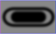
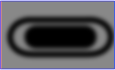
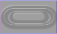
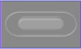


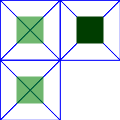
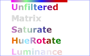

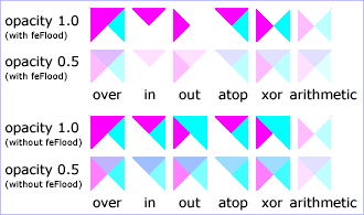
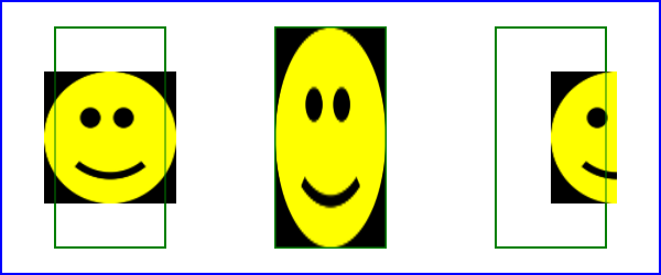
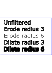
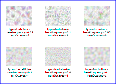
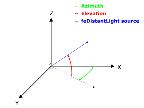


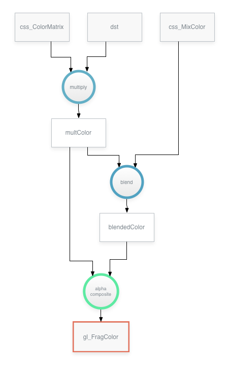
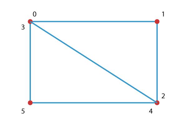
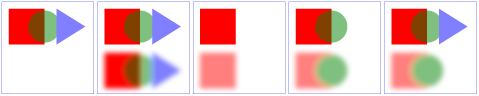