W3C

Web Audio API

W3C Working Draft 15 December 2011

This version:
http://www.w3.org/TR/2011/WD-webaudio-20111215/
Latest published version:
http://www.w3.org/TR/webaudio/
Latest editor's draft:
https://dvcs.w3.org/hg/audio/raw-file/tip/webaudio/specification.html
Previous version:
none
Public Comments:
public-audio@w3.org
Working Group:
Audio WG
Editor:
Chris Rogers, Google <crogers@google.com>

Abstract

This specification describes a high-level JavaScript API for processing and synthesizing audio in web applications. The primary paradigm is of an audio routing graph, where a number of AudioNode objects are connected together to define the overall audio rendering. The actual processing will primarily take place in the underlying implementation (typically optimized Assembly / C / C++ code), but direct JavaScript processing and synthesis is also supported.

This API is designed to be used in conjunction with other APIs and elements on the web platform, notably: XMLHttpRequest (using the responseType and response attributes). For games and interactive applications, it is anticipated to be used with the canvas 2D and WebGL 3D graphics APIs.

Status of This Document

This section describes the status of this document at the time of its publication. Other documents may supersede this document. A list of current W3C publications and the latest revision of this technical report can be found in the W3C technical reports index at http://www.w3.org/TR/.

This specification defines a proposal for an audio processing and synthesis API for use in client-side user agents (e.g. a browser). This document is accompanied by an alternative proposal, the MediaStream Processing API, and an umbrella document outlining the relationship between these proposals

This document was published by the Audio Working Group as a First Public Working Draft. This document is intended to become a W3C Recommendation. If you wish to make comments regarding this document, please send them to public-audio@w3.org (subscribe, archives). All feedback is welcome.

Web content and browser developers especially are encouraged to review this draft, and to experiment with the API and provide feedback.

Publication as a Working Draft does not imply endorsement by the W3C Membership. This is a draft document and may be updated, replaced or obsoleted by other documents at any time. It is inappropriate to cite this document as other than work in progress.

This document was produced by a group operating under the 5 February 2004 W3C Patent Policy. W3C maintains a public list of any patent disclosures made in connection with the deliverables of the group; that page also includes instructions for disclosing a patent. An individual who has actual knowledge of a patent which the individual believes contains Essential Claim(s) must disclose the information in accordance with section 6 of the W3C Patent Policy.

Table of Contents

1. Introduction

This section is informative.

Audio on the web has been fairly primitive up to this point and until very recently has had to be delivered through plugins such as Flash and QuickTime. The introduction of the audio element in HTML5 is very important, allowing for basic streaming audio playback. But, it is not powerful enough to handle more complex audio applications. For sophisticated web-based games or interactive applications, another solution is required. It is a goal of this specification to include the capabilities found in modern game audio engines as well as some of the mixing, processing, and filtering tasks that are found in modern desktop audio production applications.

The APIs have been designed with a wide variety of use cases in mind. Ideally, it should be able to support any use case which could reasonably be implemented with an optimized C++ engine controlled via JavaScript and run in a browser. That said, modern desktop audio software can have very advanced capabilities, some of which would be difficult or impossible to build with this system. Apple's Logic Audio is one such application which has support for external MIDI controllers, arbitrary plugin audio effects and synthesizers, highly optimized direct-to-disk audio file reading/writing, tightly integrated time-stretching, and so on. Nevertheless, the proposed system will be quite capable of supporting a large range of reasonably complex games and interactive applications, including musical ones. And it can be a very good complement to the more advanced graphics features offered by WebGL. The API has been designed so that more advanced capabilities can be added at a later time.

Web content creators are encouraged to try the samples and demos.

A history of changes to this specification is available.

1.1. Features

The API supports these primary features:

  • Modular routing for simple or complex mixing/effect architectures, including multiple sends and submixes.
  • Sample-accurate scheduled sound playback with low latency for musical applications requiring a very high degree of rhythmic precision such as drum machines and sequencers. This also includes the possibility of dynamic creation of effects.
  • Automation of audio parameters for envelopes, fade-ins / fade-outs, granular effects, filter sweeps, LFOs etc.
  • Processing of audio sources from an audio or video media element.
  • Audio stream synthesis and processing directly in JavaScript.
  • Spatialized audio supporting a wide range of 3D games and immersive environments:
    • Panning models: equal-power, HRTF, sound-field, pass-through
    • Distance Attenuation
    • Sound Cones
    • Obstruction / Occlusion
    • Doppler Shift
    • Source / Listener based
  • A convolution engine for a wide range of linear effects, especially very high-quality room effects. Here are some examples of possible effects:
    • Small / large room
    • Cathedral
    • Concert hall
    • Cave
    • Tunnel
    • Hallway
    • Forest
    • Amphitheater
    • Sound of a distant room through a doorway
    • Extreme filters
    • Strange backwards effects
    • Extreme comb filter effects
  • Dynamics compression for overall control and sweetening of the mix
  • Efficient real-time time-domain and frequency analysis / music visualizer support
  • Efficient biquad filters for lowpass, highpass, and other common filters.
  • A Waveshaping effect for distortion and other non-linear effects.

1.2. Modular Routing

Modular routing allows arbitrary connections between different AudioNode objects. Each node can have inputs and/or outputs. An AudioSourceNode has no inputs and a single output. An AudioDestinationNode has one input and no outputs and represents the final destination to the audio hardware. Other nodes such as filters can be placed between the AudioSourceNode nodes and the final AudioDestinationNode node. The developer doesn't have to worry about low-level stream format details when two objects are connected together; the right thing just happens. For example, if a mono audio stream is connected to a stereo input it should just mix to left and right channels appropriately.

In the simplest case, a single source can be routed directly to the output. All routing occurs within an AudioContext containing a single AudioDestinationNode:

Audio graph illustrating source node to destination node

Illustrating this simple routing, here's a simple example playing a single sound:

ECMAScript
 

            var context = new AudioContext();

            function playSound() {
                var source = context.createBufferSource();
                source.buffer = dogBarkingBuffer;
                source.connect(context.destination);
                source.noteOn(0);
            }
                    

Here's a more complex example with three sources and a convolution reverb sent with a dynamics compressor at the final output stage:

Audio graph illustrating complex example with three sources and a convolution reverb sent with a dynamics compressor at the final output stage

ADD JAVASCRIPT EXAMPLE CODE HERE...

1.3. API Overview

The interfaces defined are:

2. Conformance

Everything in this specification is normative except for examples and sections marked as being informative.

The keywords “MUST”, “MUST NOT”, “REQUIRED”, “SHALL”, “SHALL NOT”, “RECOMMENDED”, “MAY” and “OPTIONAL” in this document are to be interpreted as described in Key words for use in RFCs to Indicate Requirement Levels [RFC2119].

The following conformance classes are defined by this specification:

conforming implementation

A user agent is considered to be a conforming implementation if it satisfies all of the MUST-, REQUIRED- and SHALL-level criteria in this specification that apply to implementations.

3. Terminology and Algorithms

This specification includes algorithms (steps) as part of the definition of methods. Conforming implementations (referred to as "user agents" from here on) MAY use other algorithms in the implementation of these methods, provided the end result is the same.

4. The Audio API

4.1. The AudioContext Interface

This interface represents a set of AudioNode objects and their connections. It allows for arbitrary routing of signals to the AudioDestinationNode (what the user ultimately hears). Nodes are created from the context and are then connected together. In most use cases, only a single AudioContext is used per document. An AudioContext is constructed as follows:

        var context = new AudioContext();
        
        // For implementation WebKit this will be:
        var context = new webkitAudioContext();
        

IDL
 

        interface AudioContext {

            readonly attribute AudioDestinationNode destination;
            readonly attribute float sampleRate;
            readonly attribute float currentTime;
            readonly attribute AudioListener listener;

            AudioBuffer createBuffer(in unsigned long numberOfChannels, in unsigned long length, in float sampleRate);
            AudioBuffer createBuffer(in ArrayBuffer buffer, in boolean mixToMono);
            
            void decodeAudioData(in ArrayBuffer audioData,
                                 in [Callback] AudioBufferCallback successCallback,
                                 in [Optional, Callback] AudioBufferCallback errorCallback)
                raises(DOMException);
            

            // AudioNode creation          
            AudioBufferSourceNode createBufferSource();
            JavaScriptAudioNode createJavaScriptNode(in short bufferSize, in short numberOfInputs, in short numberOfOutputs);
            RealtimeAnalyserNode createAnalyser();
            AudioGainNode createGainNode();
            DelayNode createDelayNode();
            BiquadFilterNode createBiquadFilter();
            AudioPannerNode createPanner();
            ConvolverNode createConvolver();
            AudioChannelSplitter createChannelSplitter();
            AudioChannelMerger createChannelMerger();
            DynamicsCompressorNode createDynamicsCompressor();

        }
        

4.1.1. Attributes

destination

An AudioDestinationNode with a single input representing the final destination for all audio (to be rendered to the audio hardware). All AudioNodes actively rendering audio will directly or indirectly connect to destination.

sampleRate

The sample rate (in sample-frames per second) at which the AudioContext handles audio. It is assumed that all AudioNodes in the context run at this rate. In making this assumption, sample-rate converters or "varispeed" processors are not supported in real-time processing.

currentTime

This is a time in seconds which starts at zero when the context is created and increases in real-time. All scheduled times are relative to it. This is not a "transport" time which can be started, paused, and re-positioned. It is always moving forward. A GarageBand-like timeline transport system can be very easily built on top of this (in JavaScript). This time corresponds to an ever-increasing hardware timestamp.

listener

An AudioListener which is used for 3D spatialization.

4.1.2. Methods and Parameters

The createBuffer method

Creates an AudioBuffer of the given size. The audio data in the buffer will be zero-initialized (silent).

The numberOfChannels parameter determines how many channels the buffer will have.

The length parameter determines the size of the buffer in sample-frames.

The sampleRate parameter describes the sample-rate of the linear PCM audio data in the buffer in sample-frames per second.

The createBuffer from ArrayBuffer method

Creates an AudioBuffer given the audio file data contained in the ArrayBuffer. The ArrayBuffer can, for example, be loaded from an XMLHttpRequest with the new responseType and response attributes.

The buffer parameter contains the audio file data (for example from a .wav file).

The mixToMono parameter determines if a mixdown to mono will be performed. Normally, this would not be set.

The decodeAudioData method

Asynchronously decodes the audio file data contained in the ArrayBuffer. The ArrayBuffer can, for example, be loaded from an XMLHttpRequest with the new responseType and response attributes. Audio file data can be in any of the formats supported by the audio element.

The decodeAudioData() method is preferred over the createBuffer() from ArrayBuffer method because it is asynchronous and does not block the main JavaScript thread.

audioData is an ArrayBuffer containing audio file data.

successCallback is a callback function which will be invoked when the decoding is finished. The single argument to this callback is an AudioBuffer representing the decoded PCM audio data.

errorCallback is a callback function which will be invoked if there is an error decoding the audio file data.

The createBufferSource method

Creates an AudioBufferSourceNode.

The createJavaScriptNode method

Creates a JavaScriptAudioNode for direct audio processing using JavaScript.

The bufferSize parameter determines the buffer size in units of sample-frames. It must be one of the following values: 256, 512, 1024, 2048, 4096, 8192, 16384. This value controls how frequently the onaudioprocess event handler is called and how many sample-frames need to be processed each call. Lower values for bufferSize will result in a lower (better) latency. Higher values will be necessary to avoid audio breakup and glitches. The value chosen must carefully balance between latency and audio quality.

The numberOfInputs parameter determines the number of inputs.

The numberOfOutputs parameter determines the number of outputs.

It is invalid for both numberOfInputs and numberOfOutputs to be zero.

The createAnalyser method

Creates a RealtimeAnalyserNode.

The createGainNode method

Creates an AudioGainNode.

The createDelayNode method

Creates a DelayNode representing a variable delay line. The initial default delay time will be 0 seconds.

The createBiquadFilter method

Creates a BiquadFilterNode representing a second order filter which can be configured as one of several common filter types.

The createPanner method

Creates an AudioPannerNode.

The createConvolver method

Creates a ConvolverNode.

The createChannelSplitter method

Creates an AudioChannelSplitter representing a channel splitter.

The createChannelMerger method

Creates an AudioChannelMerger representing a channel merger.

The createDynamicsCompressor method

Creates a DynamicsCompressorNode.

4.2. The AudioNode Interface

AudioNodes are the building blocks of an AudioContext. This interface represents audio sources, the audio destination, and intermediate processing modules. These modules can be connected together to form processing graphs for rendering audio to the audio hardware. Each node can have inputs and/or outputs. An AudioSourceNode has no inputs and a single output. An AudioDestinationNode has one input and no outputs and represents the final destination to the audio hardware. Most processing nodes such as filters will have one input and one output.

IDL
 

    interface AudioNode {

        void connect(in AudioNode destination, in unsigned long output = 0, in unsigned long input = 0);
        void disconnect(in int output = 0);
        readonly attribute AudioContext context;
        readonly attribute unsigned long numberOfInputs;
        readonly attribute unsigned long numberOfOutputs;

    }
    

4.2.1. Attributes

context

The AudioContext which owns this AudioNode.

numberOfInputs

The number of inputs feeding into the AudioNode. This will be 0 for an AudioSourceNode.

numberOfOutputs

The number of outputs coming out of the AudioNode. This will be 0 for an AudioDestinationNode.

4.2.2. Methods and Parameters

The connect method

Connects the AudioNode to another AudioNode.

The destination parameter is the AudioNode to connect to.

The output parameter is an index describing which output of the AudioNode from which to connect. An out-of-bound value throws an exception.

The input parameter is an index describing which input of the destination AudioNode to connect to. An out-of-bound value throws an exception.

It is possible to connect an AudioNode output to more than one input with multiple calls to connect(). Thus, "fanout" is supported.

The disconnect method

Disconnects an AudioNode's output.

The output parameter is an index describing which output of the AudioNode to disconnect.

4.3. The AudioSourceNode Interface

This is an abstract interface representing an audio source, an AudioNode which has no inputs and a single output:

      numberOfInputs  : 0
      numberOfOutputs : 1
      

Subclasses of AudioSourceNode will implement specific types of audio sources.

IDL
 

    interface AudioSourceNode : AudioNode {

    }
    

4.4. The AudioDestinationNode Interface

This is an AudioNode representing the final audio destination and is what the user will ultimately hear. It can be considered as an audio output device which is connected to speakers. All rendered audio to be heard will be routed to this node, a "terminal" node in the AudioContext's routing graph. There is only a single AudioDestinationNode per AudioContext, provided through the destination attribute of AudioContext.

      numberOfInputs  : 1
      numberOfOutputs : 0
      
IDL
 

    interface AudioDestinationNode : AudioNode {

        readonly attribute unsigned long numberOfChannels;

    }
    

4.4.1. Attributes

numberOfChannels

The number of channels of the destination's input.

4.5. The AudioParam Interface

AudioParam is a parameter controlling an individual aspect of an AudioNode's functioning, such as volume. The parameter can be set immediately to a particular value using the "value" attribute. Additionally, value changes can be scheduled to happen at very precise times, for envelopes, volume fades, LFOs, filter sweeps, grain windows, etc. In this way, arbitrary timeline-based automation curves can be set on any AudioParam.

IDL
 

    interface AudioParam {

        attribute float value;
        readonly attribute float minValue;
        readonly attribute float maxValue;
        readonly attribute float defaultValue;

        readonly attribute DOMString name;

        // Should define units constants here (seconds, decibels, cents, etc.)          
        
        readonly attribute short units;

        // Parameter automation. 
        void setValueAtTime(in float value, in float time);
        void linearRampToValueAtTime(in float value, in float time);
        void exponentialRampToValueAtTime(in float value, in float time);

        // Exponentially approach the target value with a rate having the given time constant. 
        void setTargetValueAtTime(in float targetValue, in float time, in float timeConstant);

        // Sets an array of arbitrary parameter values starting at time for the given duration. 
        // The number of values will be scaled to fit into the desired duration. 
        void setValueCurveAtTime(in Float32Array values, in float time, in float duration);
        
        // Cancels all scheduled parameter changes with times greater than or equal to startTime. 
        void cancelScheduledValues(in float startTime);

    }
    

4.5.1. Attributes

value

The parameter's floating-point value. If a value is set outside the allowable range described by minValue and maxValue an exception is thrown.

minValue

Minimum value. The value attribute must not be set lower than this value.

maxValue

Maximum value. The value attribute must be set lower than this value.

defaultValue

Initial value for the value attribute

name

The name of the parameter.

units

Represents the type of value (seconds, decibels, cents, etc.).

4.5.2. Methods and Parameters

The setValueAtTime method

Schedules a parameter value change at the given time (relative to the AudioContext .currentTime).

The value parameter is the value the parameter will change to at the given time.

The time parameter is the time (relative to the AudioContext .currentTime).

The linearRampToValueAtTime method

Schedules a linear continuous change in parameter value from the previous scheduled parameter value to the given value.

The value parameter is the value the parameter will linearly ramp to at the given time.

The time parameter is the time (relative to the AudioContext .currentTime).

The exponentialRampToValueAtTime method

Schedules an exponential continuous change in parameter value from the previous scheduled parameter value to the given value. Parameters representing filter frequencies and playback rate are best changed exponentially because of the way humans perceive sound.

The value parameter is the value the parameter will exponentially ramp to at the given time.

The time parameter is the time (relative to the AudioContext .currentTime).

The setTargetValueAtTime method

Start exponentially approaching the target value at the given time with a rate having the given time constant. Among other uses, this is useful for implementing the "decay" and "release" portions of an ADSR envelope. Please note that the parameter value does not immediately change to the target value at the given time, but instead gradually changes to the target value.

The targetValue parameter is the value the parameter will *start* changing to at the given time.

The time parameter is the time (relative to the AudioContext .currentTime).

The timeConstant parameter is the time-constant value of first-order filter (exponential) approach to the target value. The larger this value is, the slower the transition will be.

The setValueCurveAtTime method

Sets an array of arbitrary parameter values starting at the given time for the given duration. The number of values will be scaled to fit into the desired duration.

The values parameter is a Float32Array representing a parameter value curve. These values will apply starting at the given time and lasting for the given duration.

The time parameter is the starting time for the curve values (relative to the AudioContext .currentTime).

The duration parameter is the time-constant value of first-order filter (exponential) approach to the target value.

The cancelScheduledValues method

Cancels all scheduled parameter changes with times greater than or equal to startTime.

The startTime parameter is the starting time at and after which any previously scheduled parameter changes will be cancelled.

4.6. AudioGain

This interface is a particular type of AudioParam which specifically controls the gain (volume) of some aspect of the audio processing. The unit type is "linear gain". The minValue is 0.0, and although the nominal maxValue is 1.0, higher values are allowed (no exception thrown).

IDL
 

  interface AudioGain : AudioParam {

  };
  

4.7. The AudioGainNode Interface

Changing the gain of an audio signal is a fundamental operation in audio applications. This interface is an AudioNode with a single input and single output:

    numberOfInputs  : 1
    numberOfOutputs : 1
    

which changes the gain of (scales) the incoming audio signal by a certain amount. The default amount is 1.0 (no gain change). The AudioGainNode is one of the building blocks for creating mixers. The implementation must make gain changes to the audio stream smoothly, without introducing noticeable clicks or glitches. This process is called "de-zippering".

IDL
 

    interface AudioGainNode : AudioNode {

        AudioGain gain;

    }
    

4.7.1. Attributes

gain

An AudioGain object representing the amount of gain to apply. The default value (gain.value) is 1.0 (no gain change). See AudioGain for more information.

4.8. The DelayNode Interface

A delay-line is a fundamental building block in audio applications. This interface is an AudioNode with a single input and single output:

    numberOfInputs  : 1
    numberOfOutputs : 1
    

which delays the incoming audio signal by a certain amount. The default amount is 0.0 seconds (no delay). When the delay time is changed, the implementation must make the transition smoothly, without introducing noticeable clicks or glitches to the audio stream.

IDL
 

    interface DelayNode : AudioNode {

        AudioParam delayTime;

    }
    

4.8.1. Attributes

delayTime

An AudioParam object representing the amount of delay (in seconds) to apply. The default value (delayTime.value) is 0.0 (no delay). The minimum value is 0.0 and the maximum value is currently 1.0 (but this is arbitrary and could be increased).

4.9. The AudioBuffer Interface

This interface represents a memory-resident audio asset (for one-shot sounds and other short audio clips). Its format is non-interleaved linear PCM with a nominal range of -1.0 -> +1.0. It can contain one or more channels. It is analogous to a WebGL texture. Typically, it would be expected that the length of the PCM data would be fairly short (usually somewhat less than a minute). For longer sounds, such as music soundtracks, streaming should be used with the audio element and MediaElementAudioSourceNode.

IDL
 

    interface AudioBuffer {

        // linear gain (default 1.0)          
        attribute AudioGain gain;
        
        readonly attribute float sampleRate;
        readonly attribute float length;

        // in seconds          
        readonly attribute float duration;  

        readonly attribute int numberOfChannels;

        Float32Array getChannelData(in unsigned long channel);

    }
    

4.9.1. Attributes

gain

The amount of gain to apply when using this buffer in any AudioBufferSourceNode. The default value is 1.0.

sampleRate

The sample-rate for the PCM audio data in samples per second.

length

Length of the PCM audio data in sample-frames.

duration

Duration of the PCM audio data in seconds.

numberOfChannels

The number of discrete audio channels.

4.9.2. Methods and Parameters

The getChannelData method

Gets direct access to the audio data stored in an AudioBuffer.

The channel parameter is an index representing the particular channel to get data for.

4.10. The AudioBufferSourceNode Interface

This interface represents an audio source from an in-memory audio asset in an AudioBuffer. It generally will be used for short audio assets which require a high degree of scheduling flexibility (can playback in rhythmically perfect ways).

    numberOfInputs  : 0
    numberOfOutputs : 1
    
IDL
 

    interface AudioBufferSourceNode : AudioSourceNode {

        // Playback this in-memory audio asset     
        // Many sources can share the same buffer     
        attribute AudioBuffer buffer;

        readonly attribute AudioGain gain;
        attribute AudioParam playbackRate; 
        attribute boolean loop;

        void noteOn(in float when);
        void noteGrainOn(in float when, in float grainOffset, in float grainDuration);
        void noteOff(in float when);

    }
    

4.10.1. Attributes

buffer

Represents the audio asset to be played.

gain

The default gain at which to play back the buffer. The default gain.value is 1.0.

playbackRate

The speed at which to render the audio stream. The default playbackRate.value is 1.0.

loop

Indicates if the audio data should play in a loop.

4.10.2. Methods and Parameters

The noteOn method

Schedules a sound to playback at an exact time.

The when parameter describes at what time (in seconds) the sound should start playing. This time is relative to the currentTime attribute of the AudioContext. If 0 is passed in for this value or if the value is less than currentTime, then the sound will start playing immediately.

The noteGrainOn method

Schedules a portion of a sound to playback at an exact time.

The when parameter describes at what time (in seconds) the sound should start playing. This time is relative to the currentTime attribute of the AudioContext. If 0 is passed in for this value or if the value is less than currentTime, then the sound will start playing immediately.

The grainOffset parameter describes the offset in the buffer (in seconds) for the portion to be played.

The grainDuration parameter describes the duration of the portion (in seconds) to be played.

The noteOff method

Schedules a sound to stop playback at an exact time.

The when parameter describes at what time (in seconds) the sound should stop playing. This time is relative to the currentTime attribute of the AudioContext. If 0 is passed in for this value or if the value is less than currentTime, then the sound will stop playing immediately.

4.11. The MediaElementAudioSourceNode Interface

This interface represents an audio source from an audio or video element. The element's audioSource attribute implements this.

    numberOfInputs  : 0
    numberOfOutputs : 1
    
IDL
 

    interface MediaElementAudioSourceNode : AudioSourceNode {

    }
    

4.12. The JavaScriptAudioNode Interface

This interface is an AudioNode which can generate, process, or analyse audio directly using JavaScript. It can have a variable number of inputs and outputs, although it must have at least one input or output. A basic implementation may choose not to support more than one input or output.

    numberOfInputs  : N >= 0
    numberOfOutputs : M >= 0
    (either N or M must be greater than zero)
    

The JavaScriptAudioNode is constructed with a bufferSize which must be one of the following values: 256, 512, 1024, 2048, 4096, 8192, 16384. This value controls how frequently the onaudioprocess event handler is called and how many sample-frames need to be processed each call. Lower numbers for bufferSize will result in a lower (better) latency. Higher numbers will be necessary to avoid audio breakup and glitches. The value chosen must carefully balance between latency and audio quality.

numberOfInputs and numberOfOutputs determine the number of inputs and number of outputs. It is invalid for both numberOfInputs and numberOfOutputs to be zero.

    var node = context.createJavaScriptNode(bufferSize, numberOfInputs, numberOfOutputs);
    
IDL
 

    interface JavaScriptAudioNode : AudioNode {

        attribute EventListener onaudioprocess;
        
        readonly attribute long bufferSize;

    }
    

4.12.1. Attributes

onaudioprocess

An event listener which is called periodically for audio processing. An event of type AudioProcessingEvent will be passed to the event handler.

bufferSize

The size of the buffer (in sample-frames) which needs to be processed each time onprocessaudio is called. Legal values are (256, 512, 1024, 2048, 4096, 8192, 16384).

4.13. The AudioProcessingEvent Interface

This interface is a type of Event which is passed to the onaudioprocess event handler used by JavaScriptAudioNode.

The event handler processes audio from the inputs (if any) by accessing the audio data from the inputBuffer attribute. The audio data which is the result of the processing (or the synthesized data if there are no inputs) is then placed into the outputBuffer.

IDL
 

    interface AudioProcessingEvent : Event {

        JavaScriptAudioNode node;
        readonly attribute float playbackTime;
        readonly attribute sequence <AudioBuffer> inputBuffer;
        readonly attribute sequence <AudioBuffer> outputBuffer; 

    }
    

4.13.1. Attributes

node

The JavaScriptAudioNode associated with this processing event.

playbackTime

The time when the audio will be played. This time is in relation to the context's currentTime attribute. playbackTime allows for very tight synchronization between processing directly in JavaScript with the other events in the context's rendering graph.

inputBuffer

An array of AudioBuffers (one per input) containing the input audio data. The length of this array is equal to the number of inputs of the associated JavaScriptAudioNode.

outputBuffer

An array of AudioBuffers (one per output) where the output audio data should be written. The length of this array is equal to the number of outputs of the associated JavaScriptAudioNode.

4.14. The AudioPannerNode Interface

This interface represents a processing node which positions / spatializes an incoming audio stream in three-dimensional space. The spatialization is in relation the the AudioContext's AudioListener (listener attribute).

    numberOfInputs  : 1
    numberOfOutputs : 1
    
IDL
 

    interface AudioPannerNode : AudioNode {

        // Panning model          
        const unsigned short EQUALPOWER = 0;
        const unsigned short HRTF = 1;
        const unsigned short SOUNDFIELD = 2;

        // Default for stereo is HRTF 
        attribute unsigned short panningModel;

        // Uses a 3D cartesian coordinate system 
        void setPosition(in float x, in float y, in float z);
        void setOrientation(in float x, in float y, in float z);
        void setVelocity(in float x, in float y, in float z);

        // Distance model and attributes          
        attribute unsigned short distanceModel;
        attribute float refDistance;
        attribute float maxDistance;
        attribute float rolloffFactor;

        // Directional sound cone          
        attribute float coneInnerAngle;
        attribute float coneOuterAngle;
        attribute float coneOuterGain;

        // Dynamically calculated gain values          
        readonly attribute AudioGain coneGain;
        readonly attribute AudioGain distanceGain;

    };
    

4.14.1. Constants

EQUALPOWER

A simple and efficient spatialization algorithm using equal-power panning.

HRTF

A higher quality spatialization algorithm using a convolution with measured impulse responses from human subjects. This panning method renders stereo output.

SOUNDFIELD

An algorithm which spatializes multi-channel audio using sound field algorithms.

4.14.2. Attributes

listener

Represents the listener whose position and orientation is used together with the panner's position and orientation to determine how the audio will be spatialized.

panningModel

Determines which spatialization algorithm will be used to position the audio in 3D space. See the constants for the available choices. The default is HRTF.

distanceModel

Determines which algorithm will be used to reduce the volume of an audio source as it moves away from the listener. TODO: add constants

refDistance

A reference distance for reducing volume as source move further from the listener.

maxDistance

The maximum distance between source and listener, after which the volume will not be reduced any further.

rolloffFactor

Describes how quickly the volume is reduced as source moves away from listener.

coneInnerAngle

A parameter for directional audio sources, this is an angle, inside of which there will be no volume reduction.

coneOuterAngle

A parameter for directional audio sources, this is an angle, outside of which the volume will be reduced to a constant value of coneOuterGain.

coneOuterGain

A parameter for directional audio sources, this is the amount of volume reduction outside of the coneOuterAngle.

4.14.3. Methods and Parameters

The setPosition method

Sets the position of the audio source relative to the listener attribute. A 3D cartesian coordinate system is used.

The x, y, z parameters represent the coordinates in 3D space.

The setOrientation method

Describes which direction the audio source is pointing in the 3D cartesian coordinate space. Depending on how directional the sound is (controlled by the cone attributes), a sound pointing away from the listener can be very quiet or completely silent.

The x, y, z parameters represent a direction vector in 3D space.

The setVelocity method

Sets the velocity vector of the audio source. This vector controls both the direction of travel and the speed in 3D space. This velocity relative to the listener's velocity is used to determine how much doppler shift (pitch change) to apply.

The x, y, z parameters describe a direction vector indicating direction of travel and intensity.

4.15. The AudioListener Interface

This interface represents the position and orientation of the person listening to the audio scene. All AudioPannerNode objects spatialize in relation to the AudioContext's listener. See this section for more details about spatialization.

IDL
 

    interface AudioListener {

        // linear gain (default 1.0)          
        attribute float gain;

        // same as OpenAL (default 1.0)          
        attribute float dopplerFactor;

        // in meters / second (default 343.3)          
        attribute float speedOfSound;

        // Uses a 3D cartesian coordinate system 
        void setPosition(in float x, in float y, in float z);
        void setOrientation(in float x, in float y, in float z, in float xUp, in float yUp, in float zUp);
        void setVelocity(in float x, in float y, in float z);

    };
    

4.15.1. Attributes

gain

A linear gain used in conjunction with AudioPannerNode objects when spatializing.

dopplerFactor

A constant used to determine the amount of pitch shift to use when rendering a doppler effect.

speedOfSound

The speed of sound used for calculating doppler shift. The default value is 343.3 meters / second.

4.15.2. Methods and Parameters

The setPosition method

Sets the position of the listener in a 3D cartesian coordinate space. AudioPannerNode objects use this position relative to individual audio sources for spatialization.

The x, y, z parameters represent the coordinates in 3D space.

The setOrientation method

Describes which direction the listener is pointing in the 3D cartesian coordinate space. Both a front vector and an up vector are provided.

The x, y, z parameters represent a front direction vector in 3D space.

The xUp, yUp, zUp parameters represent an up direction vector in 3D space.

The setVelocity method

Sets the velocity vector of the listener. This vector controls both the direction of travel and the speed in 3D space. This velocity relative an audio source's velocity is used to determine how much doppler shift (pitch change) to apply.

The x, y, z parameters describe a direction vector indicating direction of travel and intensity.

4.16. The ConvolverNode Interface

This interface represents a processing node which applies a linear convolution effect given an impulse response.

    numberOfInputs  : 1
    numberOfOutputs : 1
    
IDL
 

    interface ConvolverNode : AudioNode {

        // Contains the (possibly multi-channel) impulse response 
        attribute AudioBuffer buffer;

        // attribute ImpulseResponse response;

    };
    

4.16.1. Attributes

buffer

A mono or multi-channel audio buffer containing the impulse response used by the convolver.

4.17. The RealtimeAnalyserNode Interface

This interface represents a node which is able to provide real-time frequency and time-domain analysis information. The audio stream will be passed un-processed from input to output.

    numberOfInputs  : 1
    numberOfOutputs : 1    ← it has been suggested to have no outputs here - waiting for people's opinions
    
IDL
 

    interface RealtimeAnalyserNode : AudioNode {

        // Real-time frequency-domain data         
        void getFloatFrequencyData(in Float32Array array);
        void getByteFrequencyData(in Uint8Array array);

        // Real-time waveform data         
        void getByteTimeDomainData(in Uint8Array array);

        attribute unsigned long fftSize;
        readonly attribute unsigned long frequencyBinCount;

        attribute float minDecibels;
        attribute float maxDecibels;

        attribute float smoothingTimeConstant;

    };
    

4.17.1. Attributes

fftSize

The size of the FFT used for frequency-domain analsis. This must be a power of two.

frequencyBinCount

Half the FFT size.

minDecibels

The minimum power value in the scaling range for the FFT analysis data for conversion to unsigned byte values.

maxDecibels

The maximum power value in the scaling range for the FFT analysis data for conversion to unsigned byte values.

smoothingTimeConstant

A value from 0.0 -> 1.0 where 0.0 represents no time averaging with the last analysis frame.

4.17.2. Methods and Parameters

The getFloatFrequencyData method

Copies the current frequency data into the passed floating-point array. If the array has fewer elements than the frequencyBinCount, the excess elements will be dropped.

The array parameter is where frequency-domain analysis data will be copied.

The getByteFrequencyData method

Copies the current frequency data into the passed unsigned byte array. If the array has fewer elements than the frequencyBinCount, the excess elements will be dropped.

The array parameter is where frequency-domain analysis data will be copied.

The getByteTimeDomainData method

Copies the current time-domain (waveform) data into the passed unsigned byte array. If the array has fewer elements than the frequencyBinCount, the excess elements will be dropped.

The array parameter is where time-domain analysis data will be copied.

4.18. The AudioChannelSplitter Interface

The AudioChannelSplitter is for use in more advanced applications and would often be used in conjunction with AudioChannelMerger.

    numberOfInputs  : 1
    numberOfOutputs : 6 // number of "active" (non-silent) outputs is determined by number of channels in the input
    

This interface represents an AudioNode for accessing the individual channels of an audio stream in the routing graph. It has a single input, and a number of "active" outputs which equals the number of channels in the input audio stream. For example, if a stereo input is connected to an AudioChannelSplitter then the number of active outputs will be two (one from the left channel and one from the right). There are always a total number of 6 outputs, supporting up to 5.1 output (note: this upper limit of 6 is arbitrary and could be increased to support 7.2, and higher). Any outputs which are not "active" will output silence and would typically not be connected to anything.

Example:

Audio graph illustrating 2 AudioChannelSplitter examples: a simple stereo splitter with left and right channels; and a 5.1 splitter with with channels for left, right, center, LFE, SL, and SR.

One application for AudioChannelSplitter is for doing "matrix mixing" where individual gain control of each channel is desired.

IDL
 

    interface AudioChannelSplitter : AudioNode {

    };
    

4.19. The AudioChannelMerger Interface

The AudioChannelMerger is for use in more advanced applications and would often be used in conjunction with AudioChannelSplitter.

    numberOfInputs  : 6  // number of connected inputs may be less than this
    numberOfOutputs : 1
    

This interface represents an AudioNode for combining channels from multiple audio streams into a single audio stream. It has 6 inputs, but not all of them need be connected. There is a single output whose audio stream has a number of channels equal to the sum of the numbers of channels of all the connected inputs. For example, if an AudioChannelMerger has two connected inputs (both stereo), then the output will be four channels, the first two from the first input and the second two from the second input. In another example with two connected inputs (both mono), the output will be two channels (stereo), with the left channel coming from the first input and the right channel coming from the second input.

Example:

Audio graph illustrating 2 AudioChannelMerger examples: a simple stereo merger with left and right input channels; and a 5.1 merger with with input channels for left, right, center, LFE, SL, and SR.

Be aware that it is possible to connect an AudioChannelMerger in such a way that it outputs an audio stream with a large number of channels greater than the maximum supported by the system (currently 6 channels for 5.1). In this case, if the output is connected to anything else then an exception will be thrown indicating an error condition. Thus, the AudioChannelMerger should be used in situations where the numbers of input channels is well understood.

IDL
 

    interface AudioChannelMerger : AudioNode {

    };
    

4.20. The DynamicsCompressorNode Interface

DynamicsCompressorNode is an AudioNode processor implementing a dynamics compression effect.

Dynamics compression is very commonly used in musical production and game audio. It lowers the volume of the loudest parts of the signal and raises the volume of the softest parts. Overall, a louder, richer, and fuller sound can be achieved. It is especially important in games and musical applications where large numbers of individual sounds are played simultaneous to control the overall signal level and help avoid clipping (distorting) the audio output to the speakers.

    numberOfInputs  : 1
    numberOfOutputs : 1
    
IDL
 

    interface DynamicsCompressorNode : AudioNode {

        // a few attributes such as threshold, attack, and release should be defined here.

    }
    

4.21. The BiquadFilterNode Interface

BiquadFilterNode is an AudioNode processor implementing very common low-order filters.

Low-order filters are the building blocks of basic tone controls (bass, mid, treble), graphic equalizers, and more advanced filters. Multiple BiquadFilterNode filters can be combined to form more complex filters. The filter parameters such as "frequency" can be changed over time for filter sweeps, etc. Each BiquadFilterNode can be configured as one of a number of common filter types as shown in the IDL below.

    numberOfInputs  : 1
    numberOfOutputs : 1
    
IDL
 

    interface BiquadFilterNode : AudioNode {

        // Filter type.
        const unsigned short LOWPASS = 0;
        const unsigned short HIGHPASS = 1;
        const unsigned short BANDPASS = 2;
        const unsigned short LOWSHELF = 3;
        const unsigned short HIGHSHELF = 4;
        const unsigned short PEAKING = 5;
        const unsigned short NOTCH = 6;
        const unsigned short ALLPASS = 7;

        attribute unsigned short type;
        readonly attribute AudioParam frequency; // in Hertz
        readonly attribute AudioParam Q; // Quality factor
        readonly attribute AudioParam gain; // in Decibels

    }
    

The filter types are briefly described below. We note that all of these filters are very commonly used in audio processing. In terms of implementation, they have all been derived from standard analog filter prototypes. For more technical details, we refer the reader to the excellent reference by Robert Bristow-Johnson.

4.21.1 LOWPASS

A lowpass filter allows frequencies below the cutoff frequency to pass through and attenuates frequencies above the cutoff. LOWPASS implements a standard second-order resonant lowpass filter with 12dB/octave rolloff.

frequency
The cutoff frequency above which the frequencies are attenuated
Q
Controls how peaked the response will be at the cutoff frequency. A large value makes the response more peaked.
gain
Not used in this filter type

4.21.2 HIGHPASS

A highpass filter is the opposite of a lowpass filter. Frequencies above the cutoff frequency are passed through, but frequencies below the cutoff are attenuated. HIGHPASS implements a standard second-order resonant highpass filter with 12dB/octave rolloff.

frequency
The cutoff frequency below which the frequencies are attenuated
Q
Controls how peaked the response will be at the cutoff frequency. A large value makes the response more peaked.
gain
Not used in this filter type

4.21.3 BANDPASS

A bandpass filter allows a range of frequencies to pass through and attenuates the frequencies below and above this frequency range. BANDPASS implements a second-order bandpass filter.

frequency
The center of the frequency band
Q
Controls the width of the band. The width becomes narrower as the Q value increases.
gain
Not used in this filter type

4.21.4 LOWSHELF

The lowshelf filter allows all frequencies through, but adds a boost (or attenuation) to the lower frequencies. LOWSHELF implements a second-order lowshelf filter.

frequency
The upper limit of the frequences where the boost (or attenuation) is applied.
Q
Not used in this filter type.
gain
The boost, in dB, to be applied. If the value is negative, the frequencies are attenuated.

4.21.5 HIGHSHELF

The highshelf filter is the opposite of the lowshelf filter and allows all frequencies through, but adds a boost to the higher frequencies. HIGHSHELF implements a second-order highshelf filter.

frequency
The lower limit of the frequences where the boost (or attenuation) is applied.
Q
Not used in this filter type.
gain
The boost, in dB, to be applied. If the value is negative, the frequencies are attenuated.

4.21.6 PEAKING

The peaking filter allows all frequencies through, but adds a boost (or attenuation) to a range of frequencies.

frequency
The center frequency of where the boost is applied.
Q
Controls the width of the band of frequencies that are boosted. A large value implies a narrow width.
gain
The boost, in dB, to be applied. If the value is negative, the frequencies are attenuated.

4.21.7 NOTCH

The notch filter (also known as a band-stop or band-rejection filter is the opposite of a bandpass filter. It allows all frequencies through, except for a set of frequencies.

frequency
The center frequency of where the notch is applied.
Q
Controls the width of the band of frequencies that are attenuated. A large value implies a narrow width.
gain
Not used in this filter type.

4.21.8 ALLPASS

An allpass filter allows all frequencies through, but changes the phase relationship between the various frequencies. ALLPASS implements a second-order allpass filter.

frequency
The frequency where the center of the phase transition occurs. Viewed another way, this is the frequency with maximal group delay.
Q
Controls how sharp the phase transition is at the center frequency. A larger value implies a sharper transition and a larger group delay.
gain
Not used in this filter type.

4.22. The WaveShaperNode Interface

WaveShaperNode is an AudioNode processor implementing non-linear distortion effects.

Non-linear waveshaping distortion is commonly used for both subtle non-linear warming, or more obvious distortion effects. Arbitrary non-linear shaping curves may be specified.

    numberOfInputs  : 1
    numberOfOutputs : 1
    
IDL
 

    interface WaveShaperNode : AudioNode {

        attribute Float32Array curve;

    }
    

4.22.1. Attributes

curve

The shaping curve used for the waveshaping effect. The input signal is nominally within the range -1 -> +1. Each input sample within this range will index into the shaping curve with a signal level of zero corresponding to the center value of the curve array. Any sample value less than -1 will correspond to the first value in the curve array. Any sample value less greater than +1 will correspond to the last value in the curve array.

5. Integration with the audio and video elements

A MediaElementAudioSourceNode can be "adopted" from an HTMLMediaElement using an AudioContext method.


ECMAScript
 
var mediaElement = document.getElementById('mediaElementID');
var sourceNode = context.createMediaElementSource(mediaElement);
sourceNode.connect(filterNode);

6. Mixer Gain Structure

Background

One of the most important considerations when dealing with audio processing graphs is how to adjust the gain (volume) at various points. For example, in a standard mixing board model, each input bus has pre-gain, post-gain, and send-gains. Submix and master out busses also have gain control. The gain control described here can be used to implement standard mixing boards as well as other architectures.

Summing Inputs

The inputs to AudioNodes have the ability to accept connections from multiple outputs. The input then acts as a unity gain summing junction with each output signal being added with the others:

unity-gain-summing-junction

In cases where the channel layouts of the outputs do not match, an up-mix will occur to the highest number of channels.

Gain Control

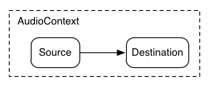
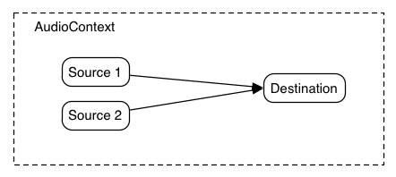
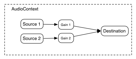
But many times, it's important to be able to control the gain for each of the output signals. The AudioGainNode gives this control:

mixer-architecture-new

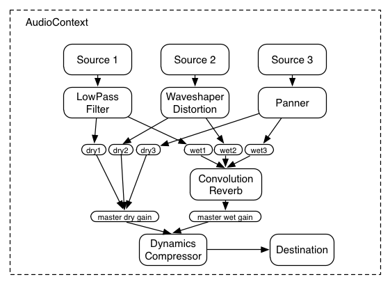
Using these two concepts of unity gain summing junctions and AudioGainNodes, it's possible to construct simple or complex mixing scenarios.

Example: Mixer with Send Busses

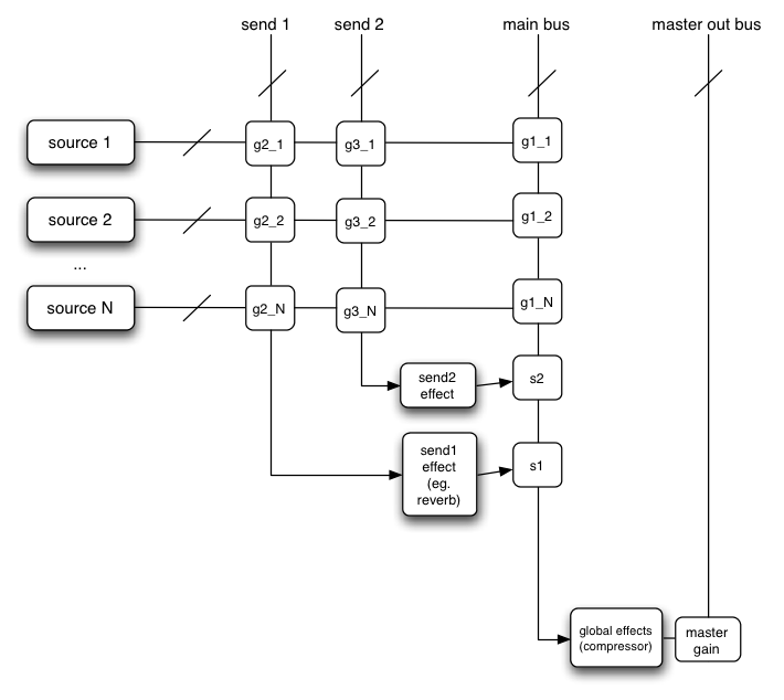
In a routing scenario involving multiple sends and submixes, explicit control is needed over the volume or "gain" of each connection to a mixer. Such routing topologies are very common and exist in even the simplest of electronic gear sitting around in a basic recording studio.

Here's an example with two send mixers and a main mixer. Although possible, for simplicity's sake, pre-gain control and insert effects are not illustrated:

mixer-gain-structure

This diagram is using a shorthand notation where "send 1", "send 2", and "main bus" are actually inputs to AudioNodes, but here are represented as summing busses, where the intersections g2_1, g3_1, etc. represent the "gain" or volume for the given source on the given mixer. In order to expose this gain, an AudioGainNode is used:
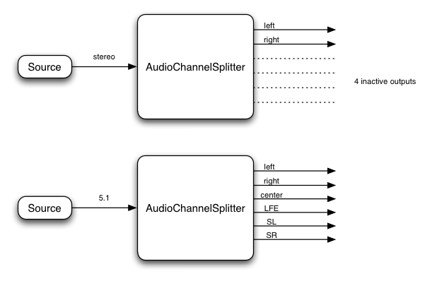
Here's how the above diagram could be constructed in JavaScript:

Example
ECMAScript
 

var context = 0;
var compressor = 0;
var reverb = 0;
var delay = 0;
var s1 = 0;
var s2 = 0;

var source1 = 0;
var source2 = 0;
var g1_1 = 0;
var g2_1 = 0;
var g3_1 = 0;
var g1_2 = 0;
var g2_2 = 0;
var g3_2 = 0;

// Setup routing graph 
function setupRoutingGraph() {
    context = new AudioContext();

    compressor = context.createDynamicsCompressor();

    // Send1 effect 
    reverb = context.createConvolver();
    // Convolver impulse response may be set here or later 

    // Send2 effect 
    delay = context.createDelayNode();

    // Connect final compressor to final destination 
    compressor.connect(context.destination);

    // Connect sends 1 & 2 through effects to main mixer 
    s1 = context.createGainNode();
    reverb.connect(s1);
    s1.connect(compressor);
    
    s2 = context.createGainNode();
    delay.connect(s2);
    s2.connect(compressor);

    // Create a couple of sources 
    source1 = context.createBufferSource();
    source2 = context.createBufferSource();
    source1.buffer = manTalkingBuffer;
    source2.buffer = footstepsBuffer;

    // Connect source1 
    g1_1 = context.createGainNode();
    g2_1 = context.createGainNode();
    g3_1 = context.createGainNode();
    source1.connect(g1_1);
    source1.connect(g2_1);
    source1.connect(g3_1);
    g1_1.connect(compressor);
    g2_1.connect(reverb);
    g3_1.connect(delay);

    // Connect source2 
    g1_2 = context.createGainNode();
    g2_2 = context.createGainNode();
    g3_2 = context.createGainNode();
    source2.connect(g1_2);
    source2.connect(g2_2);
    source2.connect(g3_2);
    g1_2.connect(compressor);
    g2_2.connect(reverb);
    g3_2.connect(delay);

    // We now have explicit control over all the volumes g1_1, g2_1, ..., s1, s2 
    g2_1.gain.value = 0.2;  // For example, set source1 reverb gain 

     // Because g2_1.gain is of type "AudioGain" which is an "AudioParam", 
     // an automation curve could also be attached to it. 
     // A "mixing board" UI could be created in canvas or WebGL controlling these gains. 
}


7. Dynamic Lifetime

Background

In addition to allowing the creation of static routing configurations, it should also be possible to do custom effect routing on dynamically allocated voices which have a limited lifetime. For the purposes of this discussion, let's call these short-lived voices "notes". Many audio applications incorporate the ideas of notes, examples being drum machines, sequencers, and 3D games with many one-shot sounds being triggered according to game play.

In a traditional software synthesizer, notes are dynamically allocated and released from a pool of available resources. The note is allocated when a MIDI note-on message is received. It is released when the note has finished playing either due to it having reached the end of its sample-data (if non-looping), it having reached a sustain phase of its envelope which is zero, or due to a MIDI note-off message putting it into the release phase of its envelope. In the MIDI note-off case, the note is not released immediately, but only when the release envelope phase has finished. At any given time, there can be a large number of notes playing but the set of notes is constantly changing as new notes are added into the routing graph, and old ones are released.

The audio system automatically deals with tearing-down the part of the routing graph for individual "note" events. A "note" is represented by an AudioBufferSourceNode, which can be directly connected to other processing nodes. When the note has finished playing, the context will automatically release the reference to the AudioBufferSourceNode, which in turn will release references to any nodes it is connected to, and so on. The nodes will automatically get disconnected from the graph and will be deleted when they have no more references. Nodes in the graph which are long-lived and shared between dynamic voices can be managed explicitly. Although it sounds complicated, this all happens automatically with no extra JavaScript handling required.

Example

Example
dynamic-allocation

The low-pass filter, panner, and second gain nodes are directly connected from the one-shot sound. So when it has finished playing the context will automatically release them (everything within the dotted line). If there are no longer any JavaScript references to the one-shot sound and connected nodes, then they will be immediately removed from the graph and deleted. The streaming source, has a global reference and will remain connected until it is explicitly disconnected. Here's how it might look in JavaScript:

ECMAScript
 

	var context = 0;
	var compressor = 0;
	var gainNode1 = 0;
	var streamingAudioSource = 0;

	// Initial setup of the "long-lived" part of the routing graph  
	function setupAudioContext() {
	    context = new AudioContext();

	    compressor = context.createDynamicsCompressor();
	    gainNode1 = context.createGainNode();

        // Create a streaming audio source.
	    var audioElement = document.getElementById('audioTagID');
	    streamingAudioSource = context.createMediaElementSource(audioElement);
	    streamingAudioSource.connect(gainNode1);

	    gainNode1.connect(compressor);
	    compressor.connect(context.destination);
	}

	// Later in response to some user action (typically mouse or key event) 
	// a one-shot sound can be played. 
	function playSound() {
	    var oneShotSound = context.createBufferSource();
	    oneShotSound.buffer = dogBarkingBuffer;

	    // Create a filter, panner, and gain node. 
	    var lowpass = context.createLowPass2Filter();
	    var panner = context.createPanner();
	    var gainNode2 = context.createGainNode();

	    // Make connections 
	    oneShotSound.connect(lowpass);
	    lowpass.connect(panner);
	    panner.connect(gainNode2);
	    gainNode2.connect(compressor);

	    // Play 0.75 seconds from now (to play immediately pass in 0.0)
	    oneShotSound.noteOn(context.currentTime + 0.75);
	}


8. Channel Layouts

It's important to define the channel ordering (and define some abbreviations) for different layouts.

The channel layouts are clear:

  Mono
    0: M: mono
    
  Stereo
    0: L: left
    1: R: right
  

A more advanced implementation can handle channel layouts for quad and 5.1:

  Quad
    0: L:  left
    1: R:  right
    2: SL: surround left
    3: SR: surround right
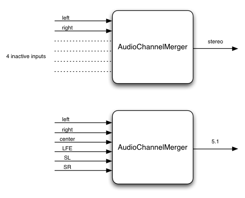
  5.1
    0: L:   left
    1: R:   right
    2: C:   center
    3: LFE: subwoofer
    4: SL:  surround left
    5: SR:  surround right
  

Other layouts can also be considered.

9. Channel up-mixing and down-mixing

For now, only considers cases for mono, stereo, quad, 5.1. Later other channel layouts can be defined.

Up Mixing

Consider what happens when converting an audio stream with a lower number of channels to one with a higher number of channels. This can be necessary when mixing several outputs together where the channel layouts differ. It can also be necessary if the rendered audio stream is played back on a system with more channels.

Mono up-mix:
    
    1 -> 2 : equal-power up-mix from mono to stereo
        output.L = 0.707 * input;
        output.R = 0.707 * input;

    1 -> 4 : equal-power up-mix from mono to quad
        output.L = 0.707 * input;
        output.R = 0.707 * input;
        output.SL = 0;
        output.SR = 0;

    1 -> 5.1 : up-mix from mono to 5.1
        output.L = 0;
        output.R = 0;
        output.C = input; // put in center channel
        output.LFE = 0;
        output.SL = 0;
        output.SR = 0;

Stereo up-mix:

    2 -> 4 : up-mix from stereo to quad
        output.L = input.L;
        output.R = input.R;
        output.SL = 0;
        output.SR = 0;

    2 -> 5.1 : up-mix from stereo to 5.1
        output.L = input.L;
        output.R = input.R;
        output.C = 0;
        output.LFE = 0;
        output.SL = 0;
        output.SR = 0;

Quad up-mix:

    4 -> 5.1 : up-mix from stereo to 5.1
        output.L = input.L;
        output.R = input.R;
        output.C = 0;
        output.LFE = 0;
        output.SL = input.SL;
        output.SR = input.SR;

Down Mixing

A down-mix will be necessary, for example, if processing 5.1 source material, but playing back stereo.

  
Mono down-mix:

    2 -> 1 : stereo to mono
        output = 0.5 * (input.L + input.R);

    4 -> 1 : quad to mono
        output = 0.25 * (input.L + input.R + input.SL + input.SR);

    5.1 -> 1 : 5.1 to mono
        ???


Stereo down-mix:

    4 -> 2 : quad to stereo
        output.L = 0.5 * (input.L + input.SL);
        output.R = 0.5 * (input.R + input.SR);

    5.1 -> 2 : 5.1 to stereo
        ???

10. Event Scheduling

Need more detail here, but for now:
  • Audio events such as start/stop play and volume fades can be scheduled to happen in a rhythmically perfect way (sample-accurate scheduling)
  • Allows sequencing applications such as drum-machines, digital-dj mixers. Ultimately, it may be useful for DAW applications.
  • Allows rhythmically accurate segueways from one section of music to another (as is possible with the FMOD engine)
  • Allows scheduling of sound "grains" for granular synthesis effects.

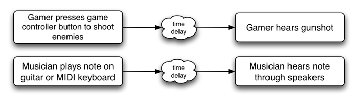
11. Spatialization / Panning

Background

A common feature requirement for modern 3D games is the ability to dynamically spatialize and move multiple audio sources in 3D space. Game audio engines such as OpenAL, FMOD, Creative's EAX, Microsoft's XACT Audio, etc. have this ability.

Using an AudioPannerNode, an audio stream can be spatialized or positioned in space relative to an AudioListener. An AudioContext will contain a single AudioListener. Both panners and listeners have a position in 3D space using a cartesian coordinate system. AudioPannerNode objects (representing the source stream) have an orientation vector representing in which direction the sound is projecting. Additionally, they have a sound cone representing how directional the sound is. For example, the sound could be omnidirectional, in which case it would be heard anywhere regardless of its orientation, or it can be more directional and heard only if it is facing the listener. AudioListener objects (representing a person's ears) have an orientation and up vector representing in which direction the person is facing. Because both the source stream and the listener can be moving, they both have a velocity vector representing both the speed and direction of movement. Taken together, these two velocities can be used to generate a doppler shift effect which changes the pitch.

Panning Algorithm

The following algorithms can be implemented:

  • Equal-power (Vector-based) panning
    This is a simple and relatively inexpensive algorithm which provides basic, but reasonable results.
  • Sound-field (Ambisonics)
    Attempts to recreate the acoustic field.
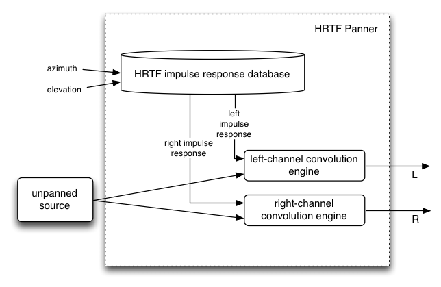
  • HRTF panning (stereo only)
    This requires a set of HRTF impulse responses recorded at a variety of azimuths and elevations. There are a small number of open/free impulse responses available. The implementation requires a highly optimized convolution function. It is somewhat more costly than "equal-power", but provides a more spatialized sound.
    HRTF_panner
  • Pass-through
    This is mostly useful for stereo sources to pass the left/right channels unpanned to the left/right speakers. Similarly for 5.0 sources, the channels can be passed unchanged.

Distance Effects

  • Sources farther away are typically quieter than nearer ones.
  • Different rolloff curves are assignable per-source: linear, inverse, exponential

Sound Cones

The listener and each sound source have an orientation vector describing which way they are facing. Each sound source's sound projection characteristics are described by an inner and outer "cone" describing the sound intensity as a function of the source/listener angle from the source's orientation vector. Thus, a sound source pointing directly at the listener will be louder than if it is pointed off-axis. Sound sources can also be omni-directional.

Doppler Shift

  • Introduces a pitch shift which can realistically simulate moving sources
  • Depends on: source / listener velocity vectors, speed of sound, doppler factor

12. Linear Effects using Convolution

Background

Convolution is a mathematical process which can be applied to an audio signal to achieve many interesting high-quality linear effects. Very often, the effect is used to simulate an acoustic space such as a concert hall, cathedral, or outdoor amphitheater. It can also be used for complex filter effects, like a muffled sound coming from inside a closet, sound underwater, sound coming through a telephone, or playing through a vintage speaker cabinet. This technique is very commonly used in major motion picture and music production and is considered to be extremely versatile and of high quality.

Each unique effect is defined by an impulse response. An impulse response can be represented as an audio file and can be recorded from a real acoustic space such as a cave, or can be synthetically generated through a great variety of techniques.

Motivation for use as a Standard

A key feature of many game audio engines (OpenAL, FMOD, Creative's EAX, Microsoft's XACT Audio, etc.) is a reverberation effect for simulating the sound of being in an acoustic space. But the code used to generate the effect has generally been custom and algorithmic (generally using a hand-tweaked set of delay lines and allpass filters which feedback into each other). In nearly all cases, not only is the implementation custom, but the code is proprietary and closed-source, each company adding its own "black magic" to achieve its unique quality. Each implementation being custom with a different set of parameters makes it impossible to achieve a uniform desired effect. And the code being proprietary makes it impossible to adopt a single one of the implementations as a standard. Additionally, algorithmic reverberation effects are limited to a relatively narrow range of different effects, regardless of how the parameters are tweaked.

A convolution effect solves these problems by using a very precisely defined mathematical algorithm as the basis of its processing. An impulse response represents an exact sound effect to be applied to an audio stream and is easily represented by an audio file which can be referenced by URL. The range of possible effects is enormous.

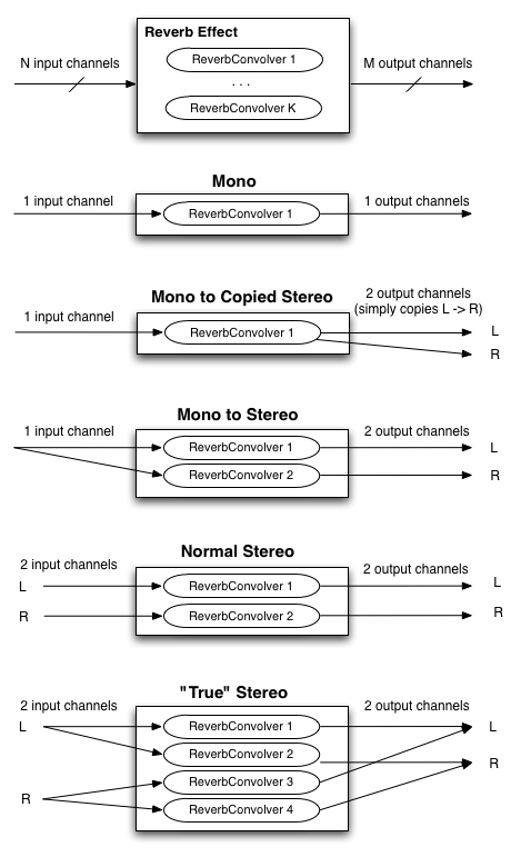
Reverb Effect (with matrixing)

Single channel convolution operates on a mono audio source, using a mono impulse response. But to achieve a more spacious sound, multi-channel audio sources and impulse responses must be considered. Audio sources and playback systems can be stereo, 5.1, or more channels. In the general case the source has N input channels, the impulse response has K channels, and the playback system has M output channels. Thus it's a matter of how to matrix these channels to achieve the final result. The following diagram, illustrates the common cases for stereo playback where N, K, and M are all less than or equal to 2. Similarly, the matrixing for 5.1 and other playback configurations can be defined.

reverb-matrixing

Recording Impulse Responses

This section is informative.

impulse-response

The most modern and accurate way to record the impulse response of a real acoustic space is to use a long exponential sine sweep. The test-tone can be as long as 20 or 30 seconds, or longer.

Several recordings of the test tone played through a speaker can be made with microphones placed and oriented at various positions in the room. It's important to document speaker placement/orientation, the types of microphones, their settings, placement, and orientations for each recording taken.

Post-processing is required for each of these recordings by performing an inverse-convolution with the test tone, yielding the impulse response of the room with the corresponding microphone placement. These impulse responses are then ready to be loaded into the convolution reverb engine to re-create the sound of being in the room.

Tools

Two command-line tools have been written:

generate_testtones generates an exponential sine-sweep test-tone and its inverse. Another tool convolve was written for post-processing. With these tools, anybody with recording equipment can record their own impulse responses. 
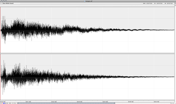
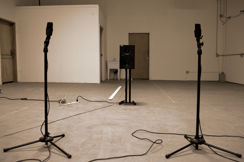
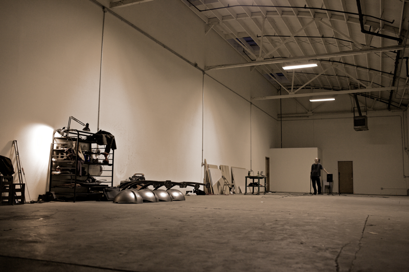
To test the tools in practice, several recordings were made in a warehouse space with interesting acoustics. These were later post-processed with the command-line tools.


% generate_testtones -h
Usage: generate_testtone
	[-o /Path/To/File/To/Create] Two files will be created: .tone and .inverse
	[-rate <sample rate>] sample rate of the generated test tones
	[-duration <duration>] The duration, in seconds, of the generated files
	[-min_freq <min_freq>] The minimum frequency, in hertz, for the sine sweep

% convolve -h
Usage: convolve input_file impulse_response_file output_file

Recording Setup

recording-setup

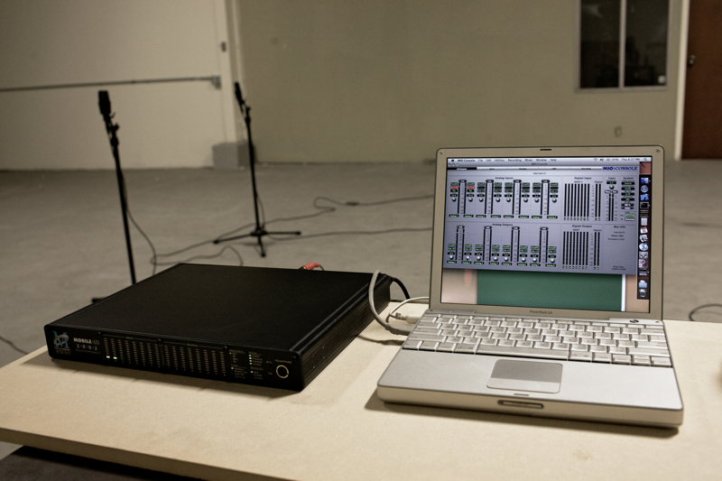
Audio Interface: Metric Halo Mobile I/O 2882


microphones-speaker

microphone speaker

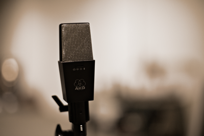
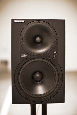
Microphones: AKG 414s, Speaker: Mackie HR824


The Warehouse Space

warehouse

13. JavaScript Synthesis and Processing

This section is informative.

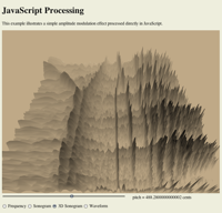
The Mozilla project has conducted Experiments to synthesize and process audio directly in JavaScript. This approach is interesting for a certain class of audio processing and they have produced a number of impressive demos. This specification includes a means of synthesizing and processing directly using JavaScript by using a special subtype of AudioNode called JavaScriptAudioNode.

Here are some interesting examples where direct JavaScript processing can be useful:

Custom DSP Effects

Unusual and interesting custom audio processing can be done directly in JS. It's also a good test-bed for prototyping new algorithms. This is an extremely rich area.

Educational Applications

JS processing is ideal for illustrating concepts in computer music synthesis and processing, such as showing the de-composition of a square wave into its harmonic components, FM synthesis techniques, etc.

JavaScript Performance

JavaScript has a variety of performance issues so it is not suitable for all types of audio processing. The approach proposed in this document includes the ability to perform computationally intensive aspects of the audio processing (too expensive for JavaScript to compute in real-time) such as multi-source 3D spatialization and convolution in optimized C++ code. Both direct JavaScript processing and C++ optimized code can be combined due to the APIs modular approach.

14. Realtime Analysis

15. Performance Considerations

15.1. Latency: What it is and Why it's Important

latency

For web applications, the time delay between mouse and keyboard events (keydown, mousedown, etc.) and a sound being heard is important.

This time delay is called latency and is caused by several factors (input device latency, internal buffering latency, DSP processing latency, output device latency, distance of user's ears from speakers, etc.), and is cummulative. The larger this latency is, the less satisfying the user's experience is going to be. In the extreme, it can make musical production or game-play impossible. At moderate levels it can affect timing and give the impression of sounds lagging behind or the game being non-responsive. For musical applications the timing problems affect rhythm. For gaming, the timing problems affect precision of gameplay. For interactive applications, it generally cheapens the users experience much in the same way that very low animation frame-rates do. Depending on the application, a reasonable latency can be from as low as 3-6 milliseconds to 25-50 milliseconds.

15.2. Audio Glitching

Audio glitches are caused by an interruption of the normal continuous audio stream, resulting in loud clicks and pops. It is considered to be a catastrophic failure of a multi-media system and must be avoided. It can be caused by problems with the threads responsible for delivering the audio stream to the hardware, such as scheduling latencies caused by threads not having the proper priority and time-constraints. It can also be caused by the audio DSP trying to do more work than is possible in real-time given the CPU's speed.

15.3. Hardware Scalability

The system should gracefully degrade to allow audio processing under resource constrained conditions without dropping audio frames.

First of all, it should be clear that regardless of the platform, the audio processing load should never be enough to completely lock up the machine. Second, the audio rendering needs to produce a clean, un-interrupted audio stream without audible glitches.

The system should be able to run on a range of hardware, from mobile phones and tablet devices to laptop and desktop computers. But the more limited compute resources on a phone device make it necessary to consider techniques to scale back and reduce the complexity of the audio rendering. For example, voice-dropping algorithms can be implemented to reduce the total number of notes playing at any given time.

Here's a list of some techniques which can be used to limit CPU usage:

15.3.1. CPU monitoring

In order to avoid audio breakup, CPU usage must remain below 100%.

The relative CPU usage can be dynamically measured for each AudioNode (and chains of connected nodes) as a percentage of the rendering time quantum. In a single-threaded implementation, overall CPU usage must remain below 100%. The measured usage may be used internally in the implementation for dynamic adjustments to the rendering. It may also be exposed through a cpuUsage attribute of AudioNode for use by JavaScript.

In cases where the measured CPU usage is near 100% (or whatever threshold is considered too high), then an attempt to add additional AudioNodes into the rendering graph can trigger voice-dropping.

15.3.2. Voice Dropping

Voice-dropping is a technique which limits the number of voices (notes) playing at the same time to keep CPU usage within a reasonable range. There can either be an upper threshold on the total number of voices allowed at any given time, or CPU usage can be dynamically monitored and voices dropped when CPU usage exceeds a threshold. Or a combination of these two techniques can be applied. When CPU usage is monitored for each voice, it can be measured all the way from the AudioSourceNode through any effect processing nodes which apply uniquely to that voice.

When a voice is "dropped", it needs to happen in such a way that it doesn't introduce audible clicks or pops into the rendered audio stream. One way to achieve this is to quickly fade-out the rendered audio for that voice before completely removing it from the rendering graph.

When it is determined that one or more voices must be dropped, there are various strategies for picking which voice(s) to drop out of the total ensemble of voices currently playing. Here are some of the factors which can be used in combination to help with this decision:

  • Older voices, which have been playing the longest can be dropped instead of more recent voices.
  • Quieter voices, which are contributing less to the overall mix may be dropped instead of louder ones.
  • Voices which are consuming relatively more CPU resources may be dropped instead of less "expensive" voices.
  • An AudioNode can have a priority attribute to help determine the relative importance of the voices.

15.3.3. Simplification of Effects Processing

Most of the effects described in this document are relatively inexpensive and will likely be able to run even on the slower mobile devices. However, the convolution effect can be configured with a variety of impulse responses, some of which will likely be too heavy for mobile devices. Generally speaking, CPU usage scales with the length of the impulse response and the number of channels it has. Thus, it is reasonable to consider that impulse responses which exceed a certain length will not be allowed to run. The exact limit can be determined based on the speed of the device. Instead of outright rejecting convolution with these long responses, it may be interesting to consider truncating the impulse responses to the maximum allowed length and/or reducing the number of channels of the impulse response.

In addition to the convolution effect. The AudioPannerNode may also be expensive if using the HRTF panning model. For slower devices, a cheaper algorithm such as EQUALPOWER can be used to conserve compute resources.

15.3.4. Sample Rate

For very slow devices, it may be worth considering running the rendering at a lower sample-rate than normal. For example, the sample-rate can be reduced from 44.1KHz to 22.05KHz. This decision must be made when the AudioContext is created, because changing the sample-rate on-the-fly can be difficult to implement and will result in audible glitching when the transition is made.

15.3.5. Pre-flighting

It should be possible to invoke some kind of "pre-flighting" code (through JavaScript) to roughly determine the power of the machine. The JavaScript code can then use this information to scale back any more intensive processing it may normally run on a more powerful machine. Also, the underlying implementation may be able to factor in this information in the voice-dropping algorithm.

TODO: add specification and more detail here

15.3.6. Authoring for different user agents

JavaScript code can use information about user-agent to scale back any more intensive processing it may normally run on a more powerful machine.

15.3.7. Scalability of Direct JavaScript Synthesis / Processing

Any audio DSP / processing code done directly in JavaScript should also be concerned about scalability. To the extent possible, the JavaScript code itself needs to monitor CPU usage and scale back any more ambitious processing when run on less powerful devices. If it's an "all or nothing" type of processing, then user-agent check or pre-flighting should be done to avoid generating an audio stream with audio breakup.

15.4. JavaScript Issues with real-time Processing and Synthesis:

While processing audio in JavaScript, it is extremely challenging to get reliable, glitch-free audio while achieving a reasonably low-latency, especially under heavy processor load.
  • JavaScript is very much slower than heavily optimized C++ code and is not able to take advantage of SSE optimizations and multi-threading which is critical for getting good performance on today's processors. Optimized native code can be on the order of twenty times faster for processing FFTs as compared with JavaScript. It is not efficient enough for heavy-duty processing of audio such as convolution and 3D spatialization of large numbers of audio sources.
  • setInterval() and XHR handling will steal time from the audio processing. In a reasonably complex game, some JavaScript resources will be needed for game physics and graphics. This creates challenges because audio rendering is deadline driven (to avoid glitches and get low enough latency).
  • JavaScript does not run in a real-time processing thread and thus can be pre-empted by many other threads running on the system.
  • Garbage Collection (and autorelease pools on Mac OS X) can cause unpredictable delay on a JavaScript thread.
  • Multiple JavaScript contexts can be running on the main thread, stealing time from the context doing the processing.
  • Other code (other than JavaScript) such as page rendering runs on the main thread.
  • Locks can be taken and memory is allocated on the JavaScript thread. This can cause additional thread preemption.
The problems are even more difficult with today's generation of mobile devices which have processors with relatively poor performance and power consumption / battery-life issues.


16. Example Applications

This section is informative.

Please see the demo page for working examples.

Here are some of the types of applications a web audio system should be able to support:

Basic Sound Playback

Simple and low-latency playback of sound effects in response to simple user actions such as mouse click, roll-over, key press.


3D Environments and Games

quake beach-demo

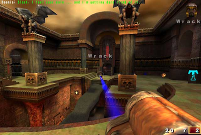
An HTML5 version of Quake has already been created. Audio features such as 3D spatialization and convolution for room simulation could be used to great effect.

3D environments with audio are common in games made for desktop applications and game consoles. 
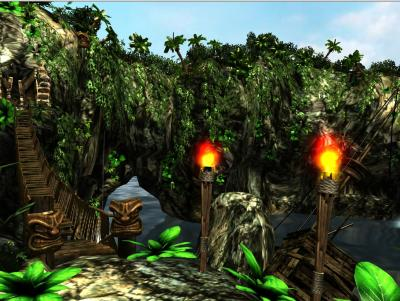
Imagine a 3D island environment with spatialized audio, seagulls flying overhead, the waves crashing against the shore, the crackling of the fire, the creaking of the bridge, and the rustling of the trees in the wind. The sounds can be positioned naturally as one moves through the scene. Even going underwater, low-pass filters can be tweaked for just the right underwater sound.


box2d 8-ball

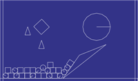
Box2D is an interesting open-source library for 2D game physics. It has various implementations, including one based on Canvas 2D. A demo has been created with dynamic sound effects for each of the object collisions, taking into account the velocities vectors and positions to spatialize the sound events, and modulate audio effect parameters such as filter cutoff.

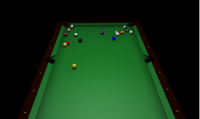
A virtual pool game with multi-sampled sound effects has also been created.


Musical Applications

garage-band shiny-drum-machine tonecraft

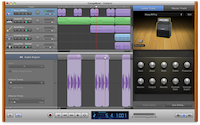
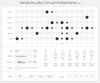
Many music composition and production applications are possible. Applications requiring tight scheduling of audio events can be implemented and can be both educational and entertaining. Drum machines, digital DJ applications, and even timeline-based digital music production software with some of the features of GarageBand can be written.
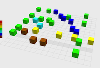
Music Visualizers

music-visualizer

When combined with WebGL GLSL shaders, realtime analysis data can be presented in entertaining ways. These can be as advanced as any found in iTunes.

Educational Applications

javascript-processing

A variety of educational applications can be written, illustrating concepts in music theory and computer music synthesis and processing.


Artistic Audio Exploration

There are many creative possibilites for artistic sonic environments for installation pieces.


17. Security Considerations

This section is informative.

18. Privacy Considerations

This section is informative. When giving various information on available AudioNodes, the Web Audio API potentially exposes information on characteristic features of the client (such as audio hardware sample-rate) to any page that makes use of the AudioNode interface. Additionally, timing information can be collected through the RealtimeAnalyzerNode or JavaScriptAudioNode interface. The information could subsequently be used to create a fingerprint of the client.

Currently audio input is not specified in this document, but it will involve gaining access to the client machine's audio input or microphone. This will require asking the user for permission in an appropriate way, perhaps via the getUserMedia() API.

19. Requirements and Use Cases

Please see Example Applications

References

Normative references

[RFC2119]
Key words for use in RFCs to Indicate Requirement Levels, Scott Bradner. IETF.

Informative references

[XHR]
XMLHttpRequest Level 2, Anne van Kesteren. W3C.