Abstract
This document describes the syntax and semantics for the Ink
Markup Language. The Ink Markup Language serves as the data
format for representing ink entered with an electronic pen or
stylus. The markup allows for the input and processing of
handwriting, gestures, sketches, music and other notational
languages in applications. It provides a common format for the
exchange of ink data between components such as handwriting and
gesture recognizers, signature verifiers, and other ink-aware
modules. It may be used in the W3C Multimodal
Interaction Framework as proposed by the W3C Multimodal Interaction
Activity .
Status of this document
This section describes the status of this document at the
time of its publication. Other documents may supersede this
document. A list of current W3C publications and the latest
revision of this technical report can be found in the W3C technical reports index at
http://www.w3.org/TR/.
This is the
11 January
10 May 2011 W3C
Candidate
Proposed Recommendation of
"Ink
"Ink Markup Language
(InkML)".
(InkML)". W3C publishes a technical
report as a
Candidate
Proposed Recommendation to indicate
that the document is
believed
a mature technical report that has received
wide review for technical soundness and implementability and
to
be stable,
request final endorsement from the W3C
Advisory Committee. Proposed Recommendation status is described in
section 7.1.1 of the
Process Document .
The W3C Membership and
other interested parties are invited to
encourage implementation by
review the
developer community.
document and send comments to the Working
Group's public mailing list www-multimodal@w3.org
( archive
) until 10 June 2011, 23:59 EDT
.See W3C mailing
list and archive usage guidelines .Advisory Committee Representatives should
consult their WBS questionnaires .
The W3C
Multimodal Working Group
believes that this specification addresses
its requirements and all Last Call and Candidate Recommendation
issues. Known implementations are documented in the InkML 1.0 Implementation Report ,
along with the associated suite of test
assertions.
This specification describes markup for representing ink entered
with an electronic pen or stylus and forms part of the proposals
for the W3C Multimodal
Interaction Framework .
Since the Candidate Recommendation in
January 2011, a number of small clarifications have been added to
the text of the specification in order to address feedback received
with the implementation reports. Changes from Candidate
Recommendation can be found in Appendix F .
Please check the Disposition of Comments
received during the Candidate Recommendation
period.
In the Candidate Recommendation phase, a
total of four implementation reports were received from four
different companies and universities. Details of the received
implementations can be found in the InkML 1.0 Implementation Report .
Sufficient implementations of all of the
features in the InkML specification were received, including those
marked at risk in the Candidate Recommendation, and so no features
from the Candidate Recommendation have been dropped from the
Proposed Recommendation.
This document has been produced as part of the W3C Multimodal
Interaction Activity , following the procedures set out for the
W3C Process ,
with the intention of advancing it along the W3C Recommendation
track. The authors of this document are members of the W3C Multimodal Interaction
Working Group .
This document was produced by a group operating under the 5
February 2004 W3C Patent Policy . W3C maintains a public list
of any patent disclosures made in connection with the
deliverables of the group; that page also includes instructions for
disclosing a patent. An individual who has actual knowledge of a
patent which the individual believes contains
Essential Claim(s) must disclose the information in accordance
with
section 6 of the W3C Patent Policy .
Publication as a
Candidate
Proposed Recommendation does not imply
endorsement by the W3C Membership. This is a draft document and may
be updated, replaced or obsoleted by other documents at any time.
It is inappropriate to cite this document as other than work in
progress.
Since the last call working draft in May
2010, a number of clarifications and examples have been added to
the text of the specification in order to address detailed feedback
on the last call. Changes from the previous Working Draft can
be found in Appendix F . Please check the Disposition of Comments
received during the Last Call period. The entrance criteria to the
Proposed Recommendation phase require at least two independently
developed interoperable implementations of each required feature,
and at least one implementation of each optional feature depending
on whether the feature's conformance requirements have an impact on
interoperability. Detailed implementation requirements and
the invitation for participation in the Implementation Report are
provided in the Implementation Report Plan . We expect to
meet all requirements of that report within the Candidate
Recommendation period closing 20 April 2011 . The Multimodal
Interaction Working Group will advance InkML to Proposed
Recommendation no sooner than 20 April 2011 . Several of the
features in the current draft specification are considered to be at
risk of removal due to potential lack of implementations. Assert ID
Feature Section 1560 The inkml:mapping element 6.1 1570 The
inkml:bind element 6.1.2 1580 The inkml:table element 6.1.3 1590
The inkml:affine element 6.1.4 The Assert IDs above refer to
assertions in the Implementation Report Plan document. Your
feedback is welcomed until 20 April 2011 . Please send
feedback to the public mailing list: www-multimodal@w3.org ( public
archives ). See W3C mailing list and archive usage guidelines
.
1 Overview
As more electronic devices with pen interfaces have and continue
to become available for entering and manipulating information,
applications need to be more effective at using this method of
input. Handwriting is a powerful and versatile input modality that
is very familiar for most users since everyone learns to write in
school. Hence, users will tend to use this as a mode of input and
control when available.
A pen-based interface is enabled by a device that allows
movements of the pen to be captured as digital ink. A number of
methods may be used for ink capture, including those based on radio
frequency, optical tracking, physical pressure, or other
technologies. Digital ink can be passed on to recognition software
that will convert the pen input into appropriate computer actions.
Alternatively, the handwritten input can be organized into ink
documents, notes or messages that can be stored for later retrieval
or exchanged through telecommunications means. Such ink documents
are appealing because they capture information as the user composed
it, including text in any mix of languages and drawings such as
equations and graphs.
Hardware and software vendors have typically stored and
represented digital ink using proprietary or restrictive formats.
The lack of a public and comprehensive digital ink format has
severely limited the capture, transmission, processing, and
presentation of digital ink across heterogeneous devices developed
by multiple vendors. In response to this need, the Ink Markup
Language (InkML) provides a simple and platform-neutral data format
to promote the interchange of digital ink between software
applications.
InkML supports a complete and accurate representation of digital
ink. In addition to the pen position over time, InkML allows
recording of information about device characteristics and detailed
dynamic behavior to support applications such as handwriting
recognition and authentication. For example, there is support to
record additional information such as pen tilt and pen tip force
(often referred to as "pressure") and information about the
recording device such as accuracy and dynamic distortion. InkML
also provides features to support rendering of digital ink captured
optically to approximate the original appearance. For example,
stroke width and color information can be recorded.
It is not within the design of InkML to describe and store
semantic information, such as the plain text of ink recognized as
handwriting. Nor is it a goal of InkML to store the
contextual information about the ink, such as what kind of field in
a form where ink was written. However, InkML provides means
for extension. InkML can include XML from other schemas at
specific locations in a file or stream (see <annotationXML>
.) Additionally, InkML could be embedded within other XML
documents.
1.1 Uses of InkML
With the establishment of a non-proprietary ink standard, a
number of applications, old and new, are expanded where the pen can
be used as a very convenient and natural form of input. Here are a
few examples.
- Ink Messaging
Two-way transmission of digital ink, possibly wireless, offers
mobile-device users a compelling new way to communicate. Users can
draw or write with a pen on the device's screen to compose a note
in their own handwriting. Such an ink note can then be addressed
and delivered to other mobile users, desktop users, or fax
machines. The recipient views the message as the sender composed
it, including text in any mix of languages and drawings.
- Ink and SMIL
A photo taken with a digital camera can be annotated with a pen;
the digital ink can be coordinated with a spoken commentary. The
ink annotation could be used for indexing the photo (for example,
one could assign different handwritten glyphs to different
categories of pictures).
- Ink Archiving and Retrieval
A software application may allow users to archive handwritten
notes and later retrieve them by a variety of mechanisms.
- Electronic Form-Filling
In support of natural and robust data entry for electronic forms
on a wide spectrum of keyboard-less devices, a developer may define
an API that takes InkML as input for fields of the form.
- Pen Input and Multimodal Systems
Robust and flexible user interfaces can be created that
integrate the pen with other input modalities such as speech.
Multimodal applications may share context information across
modalities, leading to better recognition in each modality
individually. In this setting, pen input may be used to
disambiguate voice recognition and vice-versa.
1.2 Elements
The current InkML specification defines a set of primitive
elements sufficient for all basic ink applications. All content of
an InkML document is contained within a single
<ink> element. The fundamental data element in
an InkML file is the <trace> . A trace
represents a sequence of contiguous ink points, where each point
captures the values of particular quantities such as the X and Y
coordinates of the pen's position. A sequence of traces accumulates
to meaningful units, such as characters, words or diagrams.
In its simplest form, an InkML file with its enclosed traces
looks like this:
<ink xmlns="http://www.w3.org/2003/InkML">
   <trace>
      10 0, 9 14, 8 28, 7 42, 6 56, 6 70, 8 84, 8 98, 8 112, 9 126, 10 140,
      13 154, 14 168, 17 182, 18 188, 23 174, 30 160, 38 147, 49 135,
      58 124, 72 121, 77 135, 80 149, 82 163, 84 177, 87 191, 93 205
   </trace>
   <trace>
      130 155, 144 159, 158 160, 170 154, 179 143, 179 129, 166 125,
      152 128, 140 136, 131 149, 126 163, 124 177, 128 190, 137 200,
      150 208, 163 210, 178 208, 192 201, 205 192, 214 180
   </trace>
   <trace>
      227 50, 226 64, 225 78, 227 92, 228 106, 228 120, 229 134,
      230 148, 234 162, 235 176, 238 190, 241 204
   </trace>
   <trace>
      282 45, 281 59, 284 73, 285 87, 287 101, 288 115, 290 129,
      291 143, 294 157, 294 171, 294 185, 296 199, 300 213
   </trace>
   <trace>
      366 130, 359 143, 354 157, 349 171, 352 185, 359 197,
      371 204, 385 205, 398 202, 408 191, 413 177, 413 163,
      405 150, 392 143, 378 141, 365 150
   </trace>
</ink>
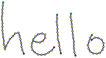
These traces consist simply of X and Y value pairs, and may look
like this when rendered:
Figure 1 shows a trace of a sampled handwriting signal. The dots
mark the sampling positions which were interpolated by the blue
line. Green points represent pen-downs whereas red dots indicate
pen-ups.
More generally, traces consist of sequences of points. Each
point consists of a number of coordinate values whose meanings are
given by a <traceFormat> element. These
coordinates may provide values for such quantities as pen position,
angle, tip force, button states and so on.
Information about the device used to collect the ink (e.g., the
sampling rate and resolution) may be specified with the
<inkSource> element.
Ink traces can have certain attributes such as color and width,
writer identification, pen modes (eraser versus writing), and so
on. These and other attributes are captured using the
<brush> element. Traces that share the same
characteristics, such as being written with the same brush, can be
grouped together with the <traceGroup>
element.
Ink traces may also be organized into collections for
application-specific purposes either by grouping the traces objects
themselves, using the <traceGroup> element, or
by reference, using the <traceView> element.
Certain applications, such as collaborative whiteboards (where
ink coming from different devices is drawn on a common canvas) or
document review (where ink annotation from various sources are
combined), will require ink sharing. The
<context> element allows representation and
grouping of the pertinent information, such as the trace format,
brush, and canvas. Canvas transformations allow ink from different
devices to be combined and manipulated by multiple parties.
InkML supports the semantic labeling of traces with attributes
on traces or collections of traces. These may be given with either
<annotation> , for text, or
<annotationXML> , for XML, using
application-defined encodings.
In all appropriate cases, the InkML specification defines
default values for elements that are not specified, and rules that
establish the scope of a given attribute.
Finally, the InkML specification is limited in scope: It is
currently oriented to fixed Cartesian coordinate systems, it does
not support sophisticated compression of trace data, and it does
not support non-ink events (although the later could be handled via
annotations).
1.3 Exchange Modes
Most ink-related applications fall into two broad categories:
"Streaming" and "Archival". Archival ink applications capture and
store digital ink for later processing, such as document
storage/retrieval applications and batch forms processing . In
these applications, an entire <ink> element is
written prior to processing. For ease of implementation in archival
mode, referenced elements should be defined inside a declaration
block using the <definitions> element (see The Default Context section, the Definitions section, and the Archival Applications section).
Streaming ink applications, on the other hand, transmit digital
ink as it is captured, such as in the electronic whiteboard example
mentioned above. In order to support a streaming style of ink
markup generation, the InkML language supports the notion of a
"current" state (e.g., the current brush) and allows for
incremental changes to this state.
1.4 Conventions used in this document
This document uses the following conventions:
- Syntax of element contents
- The syntax of the contents of InkML elements is expressed in
Backus-Naur Form, using the notation defined in the Trace section. Non-literal symbols
represent InkML markup and are linked to the relevant section in
this document. For example:
- Syntax of attribute contents
- In this specification attributes definitions are formatted as:
default = xsd:decimal | xsd:boolean
The left hand side of the '=' sign is the name of the attribute and
the right hand side describes the syntax of the attribute's
contents, using the same Backus-Naur Form notation as used for
element definitions. In addition, a non-literal symbol will
represent a data type name. By convention, this specification uses
the prefix 'xsd:' to indicate that the following name is that of a
datatype formally defined in the XML Schema Part 2: Datatypes
Recommendation [ XMLSCHEMA2
]. The 'xsd' prefix is used only as a notation in this
specification, and does not mandate any prefix when using XML
Schema names in InkML.
2 Structure
InkML documents are well-formed XML documents which comply to
the syntax rules of this specification.
The namespace URI of InkML is
http://www.w3.org/2003/InkML
The media type of InkML document is
application/inkml+xml . See the Media Type definition for details. This
media type is expected to be registered with IETF.
2.1 <ink> element
The ink element is the root element of any InkML
instance. When combining InkML and other XML elements within
applications, elements from different namespaces must be
disambiguated by use of the namespace qualifier. The allowed
sub-elements of the ink element can occur any number
of times, in any order.
Attributes:
documentID = xsd:anyURI
The unique identifier for this document.
Required: no, Default: none
A URI that uniquely identifies this document. No two documents
with a distinct application intent may have the same
documentID contents. The value of this property is an
opaque URI whose interpretation is not defined in this
specification.
Contents:
Example:
<ink xmlns="http://www.w3.org/2003/InkML"
    documentID="uuid:6B29FC40-CA47-1067-B31D-00DD010662DA">
   ...
</ink>
3 Traces and Trace Formatting
<trace> is the basic element used to record
the trajectory of a pen as the user writes digital ink. More
specifically, these recordings describe sequences of connected
points. On most devices, these sequences of points will be bounded
by pen contact change events (pen-up and pen-down), although some
devices may simply record proximity and force data without
providing an interpretation of pen-up or pen-down state.
The simplest form of encoding specifies the X and Y coordinates
of each sample point. For compactness, it may be desirable to
specify absolute coordinates only for the first point in the trace
and use delta-x and delta-y values to encode subsequent points.
Some devices record acceleration rather than absolute or relative
position; some provide additional data that may be encoded in the
trace, including Z coordinates or tip force, or the state of side
switches or buttons.
These variations in the information available from different ink
sources, or needed by different applications, are supported in
InkML through the <traceFormat> and
<trace> elements. The
<traceFormat> element specifies the encoding
format for each sample of a recorded trace, while
<trace> elements are used to represent the
actual trace data. If no <traceFormat> is
specified, a default encoding format of X followed by Y coordinates
is assumed.
Traces generated by different devices, or used in differing
applications, may contain different types of information. InkML
defines channels to describe the
data that may be encoded in a trace.
A channel can be characterized as either regular ,
meaning that its value is recorded for every sample point of the
trace, or intermittent , meaning that its value may change
infrequently and thus will not necessarily be recorded for every
sample point. X and Y coordinates are examples of likely regular
channels, while the state of a pen button is likely to be an
intermittent channel.
xml:id = xsd:ID
The unique identifier for this trace
format.
Required: no, Default: none
Contents:
The <traceFormat> element describes the
format used to encode points within <trace>
elements. In particular, it defines the sequence of channel values
that occurs within <trace> elements. The order
of declaration of channels in the <traceFormat>
element determines the order of appearance of their values within
<trace> elements.
Regular channels appear first in the <trace>
, followed by any intermittent channels. Correspondingly, the
<traceFormat> element contains an ordered
sequence of <channel> s, giving the regular
channels (if any), followed by an optional
<intermittentChannels> section. The order of the
coordinates in each point of a trace is determined by the order of
the <channel> elements in the trace format,
including those from the intermittent channels part.
The <context> element may use the
traceFormatRef attribute to refer to a
<traceFormat> by it's id. If no
<traceFormat> is specified in an InkML file, an
application defined default trace format is used. The default
trace has the reserved id "
DefaultTraceFormat " and may be
explicitly referenced using the URI "
#DefaultTraceFormat ".
3.1.2 <channel> element
xml:id = xsd:ID
The unique identifier for this element.
Required: no, Default: none
name = xsd:string
The case sensitive name of this channel.
Required: yes
type = "integer" | "decimal" | "double" | "boolean"
The data type of the point values for this
channel.
Required: no, Default: "decimal"
default = xsd:decimal | xsd:boolean
The default value of the point data for this
channel. This only applies to intermittent channels.
Required: no, Default: 0 (for integer or decimal
channel), F (for boolean channel)
min = xsd:number
The lower boundary for the values of this
channel.
Required: no, Default: none
max = xsd:number
The upper boundary for the values of this
channel.
Required: no, Default: none
orientation = "+ve" | "-ve"
The orientation of increasing channel values
with respect to the default direction of the channel's coordinate
axis, where applicable.
Required: no, Default: "+ve"
respectTo = xsd:anyURI
Specifies that the values are relative to
another reference point. The reference point may be the URI
of a <timestamp>
for time channels, or an application defined URI for application
specific channels.
Required: no, Default: none
units = xsd:string
The units in which the values of the channel
are expressed (numerical channels only).
Required: no, Default: none
Channels are described using the <channel>
element, with various attributes.
The required name attribute specifies the interpretation
of the channel in the trace data. The following case sensitive
channel names, with their specified meanings, are reserved:
| channel name |
dimension |
default unit |
interpretation |
| X |
length |
mm |
X coordinate. This is the horizontal pen position on the
writing surface, increasing to the right for +ve orientation. |
| Y |
length |
mm |
Y coordinate. This is the vertical position on the writing
surface, increasing downward for +ve orientation. |
| Z |
length |
mm |
Z coordinate. This is the height of pen above the writing
surface, increasing upward for +ve orientation. |
| F |
force |
% |
pen tip force |
| S |
|
|
tip switch state (touching/not touching the writing
surface) |
| B1...Bn |
|
|
side button states |
| OTx |
angle |
deg |
tilt along the x-axis |
| OTy |
angle |
deg |
tilt along the y-axis |
| OA |
angle |
deg |
azimuth angle of the pen (yaw) |
| OE |
angle |
deg |
elevation angle of the pen (pitch) |
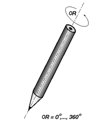
| OR |
angle |
deg |
rotation (counter-clockwise rotation about pen axis ) |
| C |
|
|
color value as an RGB octet triple (i.e. #000000 to
#FFFFFF). |
| CR,CG,CB |
|
|
color values (Red/Green/Blue) |
| CC,CM,CY,CK |
|
|
color values (Cyan/Magenta/Yellow/Black) |
| A |
|
|
transparency (device-specific encoding) |
| W |
length |
mm |
stroke width (orthogonal to stroke) |
| BW |
length |
mm |
brush width |
| BH |
length |
mm |
brush height |
| T |
time |
ms |
time (of the sample point) |
The type attribute defines the encoding type for the
channel (either boolean, decimal, or integer). If type is
not specified, it defaults to decimal.
A default value can be specified for the channel using the
default attribute; the use of default values within a trace
is described in the next section. If no default is
specified, it is assumed to be zero for integer and decimal-valued
channels, and false for boolean channels.
The min and max attributes, if given, specify the
minimum and maximum possible values for a channel of type integer
or decimal. If neither is given, then there is no a prior bound on
the channel values. If one is given, then the channel values are
bounded above or below but unbounded in the other direction. If
both are given, then all channel values must fall within the
specified range.
The orientation attribute is applicable to channels of
integer or decimal type. It gives the meaning of increasing value.
For example, whether X increases to the left or the right. The
value may be given as "+ve" or "-ve", with "+ve" being the
default.
The respectTo attribute specifies the origin for channels
of integer or decimal type. For time channels, this is given as a
URI for a <timestamp> element. For other
application defined channels the URI is application-dependent.
Typically, a channel in the <traceFormat>
will map directly to a corresponding channel provided by the
digitizing device, and its values as recorded in the trace data
will be the original channel values recorded by the device.
However, for some applications, it may be useful to store
normalized channel values instead, or even to remap the channels
provided by the digitizing device to different channels in the
trace data. This correspondence between the trace data and the
device channels is recorded using a <mapping>
element (described in the Mappings section
) within the <channel> element. If no mapping is
specified for a channel, it is assumed to be unknown.
3.1.3
<intermittentChannels> element
none
The <intermittentChannels> element
lists those channels whose value may optionally be recorded for
each sample point. The order of the enclosed channel
declarations gives the order of the intermittent channel data
samples within traces having this format. The <intermittentChannels> section
is optional and must appear after the regular
<channel> elements (if any) within a
<traceFormat> element.
3.1.4 Orientation Channels
The channels OTx, OTy, OA, OE and OR record pen orientation
data. Implementers may choose to use either pen azimuth OA and pen
elevation OE, or alternatively tilt angles OTx and OTy. The latter
are the angles of projections of the pen axis onto the XZ and YZ
planes, measured from the vertical. It is often useful to record
the sine of this angle, rather than the angle itself, as this is
usually more useful in calculations involving angles. The <mapping> element can be
employed to specify an applied sine transformation. While it is not
forbidden to use channels from different groups together (i.e. from
more than one of {OA, OE} and {OTx, OTy}), applications will not
normally do this.
The third degree of freedom in orientation is generally defined
as the rotation of the pen about its axis. This is potentially
useful (in combination with tilt) in application such as
illustration or calligraphy, and signature verification.
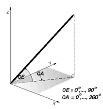
Figure 2a displays the pen orientation using Azimuth and
Elevation. The origin of the Azimuth is at the Y-axis. Azimuth
increases anticlockwise up to 360 degrees. The origin of Elevation
is located within the XY-plane. Elevation increases up to 90
degrees, at which point the pen is perpendicular to the
XY-plane.
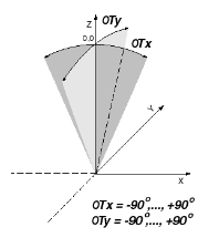
Figure 2b explains the definition of the Tilt-X and the Tilt-Y
angles. For both the origin is along the Z-axis. Tilt-X increases
up to +90 degrees for inclinations along the positive X-axis and
decreases up to -90 degrees for inclinations along the negative
X-axis. Respectively, Tilt-Y is defined for pen inclinations along
the Y-axis.
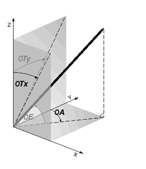
Figure 3a displays the pen orientation decomposition as
functions of Azimuth/Elevation or alternatively as function of
Tilt-X/Tilt-Y. Thereby, elevations of the pen which are mapped to
the XZ- and to the YZ- plane lead to Tilt-X and Tilt-Y.
Figure 3b shows the Rotation of the pen along its longitudinal
axis. The departure of a reference mark or meridian on the
pen barrel from the nominal 'up' direction which may be constructed
by a ray perpendicular to the pen barrel (somewhere not at the tip)
and intersecting a pure-Z ray arising from the surface of the pen
passing through the tip. This angle is measured in a clockwise
direction when viewing the pen barrel from tail to tip, in
degrees.
3.1.5 Color Channels
The channels CR, CG, CB, CC, CM, CY, CK, C and A are defined to
record color and transparency data as captured by an optical
device, as generated by software or by other means.
The channels CR, CG, CB provide an additive color model for the
colors red, green and blue. The channels CC, CY, CM, CK provide a
subtractive color model for the colors cyan, magenta, yellow and
black. The channel C provides a mechanism to give color as a single
numerical value in the range #000000..#FFFFFF that encodes the
colors red, green and blue as three octets. While it is not
forbidden to use channels from different groups together (i.e. from
more than one of {C}, {CR, CG, CB} and {CC, CY, CM, CK}),
applications will not normally do this. The A channel records
transparency as an integer. The value 0 represents opaque ink and
the maximum permissible value represents complete transparency.
Color channels are intended for use when these values are part
of the data itself and hence potentially changing from one sample
to the next. Strokes with constant color may more economically be
described with reference to a <brush>
element.
It is legitimate for an application to have an accessibility
mode or alternative rendering mode where the explicit color values
in the InkML are reinterpreted as other colors for better
accessibility or suitability of the rendering device. Examples of
this would be mapping color to black and white for monochrome
devices or to high-contrast colors for greater visibility.
3.1.6 Width Channels
Three channels are provided to provide stroke width
information.
The channel W is provided for recording stroke width. The value
is in length units and is the diameter of the larger circle that
can be inscribed within the trace locus. This allows optical
devices to record measured stroke width and allows applications
that generate InkML to specify desired width for rendering.
The channels BW and BH are defined to record the brush width and
height at each point. The meaning of the width and height is
defined by the brush tip shape, as given by a
<brushProperty>.
As with the color channels, the width channels are intended for
use when this quantity is part of the data itself and hence
potentially changing from one sample to the next. Strokes with
constant width may more economically be described with reference to
a <brush> element with width
and height properties.
3.1.7 Time Channel
The time channel allows for detailed recording of the timing
information for each sample point within a trace. This can be
useful if the digitizing device has a non-uniform sampling rate,
for example, or in cases where duplicate point data is removed for
the sake of compactness.
The time channel can be specified as either a regular or
intermittent channel. When specified as a regular channel, the
single quote prefix can be used to record incremental time between
successive points. The value of the time channel for a given
sample point is defined to be the timestamp of that point in the
units and frame of reference specified by the
respectTo attribute of the time channel that is
defined in the associated <traceFormat> of the trace.
As with the other predefined channels, the meaning of the
integer or decimal values recorded by the time channel in a given
trace is defined by the trace's associated <traceFormat> . In the case of
the time channel, its <channel> element contains
both a units and respectTo attribute.
The units attribute gives the units of the recorded time
values, and the respectTo attribute describes the frame of
reference for those recorded values. The value of the
respectTo attribute is a reference to a time stamp. If it is
not given, the time channel values are relative to the beginning
timestamps of the individual traces in which they appear.
The following example defines a time channel whose values for a
given point are the relative to the timestamp referred to by
#ts1 :
<channel name="T"
         type="integer"
         units="ms"
         respectTo="#ts1" />
If no <traceFormat> information is
provided, or if no value is specified for the respectTo
attribute, the ink processor cannot make any assumption about the
relative timing of points within different traces. Likewise, if no
units are specified, no assumption can be made about the units of
the time channel data.
3.1.8 User Defined Channels
In addition to the pre-defined channels, user-defined channels
are allowed, although their interpretation is not required by
conforming ink markup processors.
When specifying a number of related channels, it is recommended
to use a common prefix. For example, direction-sensitive stylus
force could be named FX, FY, FZ.
User defined channels may be used to describe ink traces in
non-Cartesian coordinate systems, using various compression
schemes, or with supplementary information. Channels need not
describe properties of the digital ink, per se, but may be used to
provide additional information in the ink stream. For
example, a user defined channels could give information about
changing lighting conditions.
3.1.9 Specifying Trace Formats
The following example defines a
<traceFormat> which reports decimal-valued X and
Y coordinates for each point, and intermittent boolean values for
the states of two buttons B1 and B2, which have default values of F
("false"):
<traceFormat xml:id="xyb1b2">
   <channel name="X" type="decimal">
      <mapping type="identity"/>
   </channel>
   <channel name="Y" type="decimal">
      <mapping type="identity"/>
   </channel>
   <intermittentChannels>
      <channel name="B1" type="boolean" default="F">
         <mapping type="identity"/>
      </channel>
      <channel name="B2" type="boolean" default="F">
         <mapping type="identity"/>
      </channel>
   </intermittentChannels>
</traceFormat>
The appearance of a
<traceFormat> element in an InkML file both
defines the format and installs it as the current format for
subsequent traces except within a <definitions> block (see Specifying Trace Formats ). The id
attribute of a <traceFormat> allows the format
to be reused by multiple contexts (see the Context section). If no
<traceFormat> is specified, the following
default format is assumed:
<traceFormat xml:id="DefaultTraceFormat">
    <channel name="X" type="decimal"/>
    <channel name="Y" type="decimal"/>
</traceFormat>
Thus, in the simplest case, an InkML file may contain nothing
but <trace> elements within an
<ink> element.
3.2 Traces
3.2.1 <trace> element
xml:id = xsd:ID
The identifier for this trace.
Required: no, Default: none
type = "penDown" | "penUp" | "indeterminate"
The type of this trace.
Required: no, Default: "penDown"
continuation = "begin" | "middle" | "end"
This attribute indicates whether this trace is
a trace fragment, and if so, where this trace is located in the set
of continuation traces.
Required: no, Default: none
priorRef = xsd:anyURI
The URI of the trace this one is a
continuation of.
Required: if and only if
continuation has values "end" or
"middle", Default: none
contextRef = xsd:anyURI
The context for this trace. Any values in this
context over-ride the values in the inherited context.
Required: no, Default: "
#DefaultContext ," unless this
<trace> is
contained within a <traceGroup> , then inherit
from the <traceGroup>.
brushRef = xsd:anyURI
The brush for this trace.
Required: no, Default: Inherited from context.
duration = xsd:decimal
The duration of this trace, in
milliseconds.
Required: no, Default: none
timeOffset = xsd:decimal
The relative timestamp or time-of-day for the
start of this trace, in milliseconds.
Required: no, Default: none
The following grammar defines the syntax of the data that
appears within a <trace> element. It is
described using the subset of Extended Backus-Naur Form defined in
the Notation section of the Extensible Markup
Language (XML) 1.0 (Fourth Edition) specification [ EBNF ]. This subset of EBNF includes the
following notation:
- *: 0 or more
- +: 1 or more
- ?: 0 or 1
- (): grouping
- |: separates alternatives
- double or single quotes surround literals
- #x precedes hex character codes
The grammar is as follows:
trace   ::= point ("," point)* ","? wsp*
point   ::= (wsp* value)+ wsp*
value   ::= difference_order?  wsp* "-"? wsp* number | "T" | "F" | "*" | "?"
number  ::= (decimal | double | hex)
double  ::= decimal ("e"|"E") ("+"|"-")? digit+
decimal ::= digit+ ("." digit*)? | "." digit+
hex     ::= "#" (digit | "A" | "B" | "C" | "D" | "E" | "F")+
difference_order ::= ("!" | "'" | '"')
digit   ::= ("0" | "1" | "2" | "3" | "4" | "5" | "6" | "7" | "8" | "9")
wsp     ::= (#x20 | #x9 | #xD | #xA)
Additionally,
wsp may occur anywhere except within
a
decimal, float or
hex and
must occur if
required to separate two
values . Otherwise the longest
token is matched. For example, "3245" requires an internal
wsp character if it is to be interpreted as two decimal
numbers, "32" and "45". On the other hand, "0.923.45" will be
interpreted as "0.923" and ".45".
The number of value tokens appearing within each point
must be at least equal to the number of regular channels and be no
more than the number of regular channels plus the number of
intermittent channels.
The <trace> element is used to record the
data captured by the digitizer. It contains a sequence of points
encoded according to the specification given by the
<traceFormat> element.
The type attribute of a <trace>
indicates the pen contact state (either " penUp " or "
penDown ") during its recording. A value of "
indeterminate " is used if the contact-state is
neither pen-up nor pen-down, and may be either unknown or variable
within the trace. For example, a signature may be captured as a
single indeterminate trace containing both the actual writing and
the trajectory of the pen between strokes. The values of the
tip switch state channel "S", if present in the trace, overrides
the value of the type attribute.
If a continuation attribute is present, it
indicates that the current trace is a continuation trace, i.e. its
points are a temporally contiguous continuation of (and thus should
be connected to) another trace element. The possible values of the
attribute are:
begin : the current trace is the first of the set
of continuation tracesend : the current trace is the last of the set of
continuation tracesmiddle : the current trace is a continuation
trace, but is neither the first nor the last in the set of
traces
If the current trace is a continuation trace but is not the
first trace in the set (i.e. the continuation
attribute has value middle or end ) then
a priorRef attribute must be present and must contain
the URI of the trace of which the current trace is a continuation.
A begin or middle trace can be the prior
trace for exactly one trace. An end trace cannot be
the prior trace of any other trace.
Regular channels may be reported as explicit values,
differences, or second differences: Prefix symbols are used to
indicate the interpretation of a value: a preceding exclamation
point ( ! ) indicates an explicit value, a single
quote ( ' ) indicates a single difference, and a
double quote prefix ( " ) indicates a second
difference. If there is no prefix, then the channel value is
interpreted as explicit, difference, or second difference based on
the last prefix for the channel. If there is no last prefix, the
value is interpreted as explicit.
A second difference encoding must be preceded by a single
difference representation; which, in turn, must be preceded with an
explicit encoding.
All traces must begin with an explicit value, not with a first
or second difference. This is true of continuation traces as well.
This allows the location and velocity state information to be
discarded at the end of each trace, simplifying parser
design. This is true for continuation traces.
Both regular and intermittent channels may be encoded with the
wildcard character "*". This wildcard character means either that
the value of the channel remains at the previous channel value (if
explicit), or that the channel continues integrating with the
previous velocity or acceleration values, as appropriate.
Intermittent channels may be encoded with the wildcard character
"?". This means that a value of a channel is not given at that
point. It is useful when there are several independent intermittent
channels, and they do not always report simultaneously, e.g.
<trace> 11 12 9, 21 22 ? T, 31 32, 41 42 5, 51 52 ? F</trace>
Booleans are encoded as "T" or "F".
For each point in the trace, regular channel values are reported
first in the order given by the <channel>
elements of the applicable <traceFormat> . All
regular channels must be reported, if only with the explicit
wildcard "*". If any intermittent values are reported for the
point, they are given next, in the order given by the
<intermittentChannels> elements of the
applicable <traceFormat> . Unreported
intermittent channels are interpreted as though they were given by
the wildcard "*".
Here is an example of a trace of 11 points, using
the following traceFormat:
<traceFormat>
   <channel name="X" type="decimal"/>
   <channel name="Y" type="decimal"/>
   <intermittentChannels>
      <channel name="B1" type="boolean" default="F"/>
      <channel name="B2" type="boolean" default="F"/>
   </intermittentChannels>
</traceFormat>
<trace xml:id="id4525abc">
   1125 18432,'23'43,"7"-8,3-5,7 -3,6 2,6 8,3 6 T,2 4*T,3 6,3-6 F F
</trace>
The trace is interpreted as follows:
| Trace |
X |
Y |
vx |
vy |
B1 |
B2 |
Comments |
| 1125 18432 |
1125 |
18432 |
? |
? |
F |
F |
button default values |
| '23'43 |
1148 |
18475 |
23 |
43 |
F |
F |
velocity values |
| "7"-8 |
1178 |
18510 |
30 |
35 |
F |
F |
acceleration Values |
| 3-5 |
1211 |
18540 |
33 |
30 |
F |
F |
implicit acceleration
no whitespace needed |
| 7 -3 |
1251 |
18567 |
40 |
27 |
F |
F |
optional whitespace |
| 6 2 |
1297 |
18596 |
46 |
29 |
F |
F |
whitespace required |
| 6 8 |
1349 |
18633 |
52 |
37 |
F |
F |
|
| 3 6 T |
1404 |
18676 |
55 |
43 |
T |
F |
an optional value |
| 2 4*T |
1461 |
18723 |
57 |
47 |
T |
T |
wildcard |
| 3 6 |
1521 |
18776 |
60 |
53 |
T |
T |
optional keep last |
| 3-6 F F |
1584 |
18823 |
63 |
47 |
F |
F |
optionals |
An ink markup generator might also include additional whitespace
formatting for clarity. The following trace specification is
identical in meaning to the more compact version shown above:
<trace xml:id="id4525abc">
   1125 18432,
   '23 '43,
   "7 "-8,
   3 -5,
   7 -3,
   6 2,
   6 8,
   3 6 T,
   2 4 * T,
   3 6,
   3 -6 F F
</trace>
3.3 Trace Collections
InkML provides mechanisms to gather and combine traces into
structured collections via the <traceGroup> and
<traceView> elements. These allow multiple
traces or groups to be treated as single units for the purposes of
referencing, attaching context information, semantic labeling, or
application-specific needs. The <traceGroup>
element gathers <trace> other
<traceGroup> or <traceView>
elements into a unit. The <traceView> element
refers to existing <trace> ,
<traceGroup> or other
<traceView> elements to provide alternative
views or organization on the ink. For example, a diagramming
application may record a stream of fixed-length
<trace> packages, organized as continuations,
and use <traceGroup> elements containing
<traceView> elements to record the logical
structure of the diagram.
3.3.1 <traceGroup>
element
xml:id = xsd:ID
The identifier for this traceGroup.
Required: no, Default: none
contextRef = xsd:anyURI
The context associated with this
traceGroup.
Required: no, Default: "
#DefaultContext ," unless this
<traceGroup> is
contained within another <traceGroup> , then inherit
from the containing <traceGroup>.
brushRef = xsd:anyURI
The brush associated with this <traceGroup> .
Required: no, Default: Inherited from context
The <traceGroup> element is used to group
successive traces which share common characteristics, such as the
same <traceFormat> . The brush and context
sections describe other contextual values that can be specified for
a <traceGroup> . In the following example the
two traces enclosed in the <traceGroup> share
the same brush (see the Brushes section for
a description of brushes).
<traceGroup brushRef="#penA">
    <trace>...</trace>
    <trace>...</trace>
</traceGroup>
The <traceGroup> element may be used for
various purposes, such as to group traces according to their
properties at the time of capture or according to computed
recognition results. The element may be nested, and it may be used
as a generic grouping mechanism, e.g. for the semantic labeling of
traces.
Trace groups are the primary mechanism for assigning
<context> to traces in archival ink markup. For
additional details about this usage, see the Archival Applications section.
3.3.2 <traceView>
element
xml:id = xsd:ID
The identifier for this traceView.
Required: no, Default: none
traceDataRef = xsd:anyURI
A URI reference to a
<trace> , <traceGroup> or
<traceView> element.
Required: yes, Default: none
from = xsd:integer[ ':' xsd:integer ]*
The index of the first item (point, trace or
group) in the trace or trace group that this
<traceView> element references.
Required: no, Default: the index of the first
referenced point (see prose)
to = xsd:integer[ ':' xsd:integer ]*
The index of the last item (point, trace or
group) in the trace or trace group that this
<traceView> element references.
Required: no, Default: the index of the last
referenced point (see prose)
The <traceView> element is used to include
traces by reference from the current document or other documents. A
common use is to group a collection of
<traceView> elements in a
<traceGroup> to provide annotations.
Together, traceDataRef , from
and to refer to another element and select part of
it. A traceDataRef attribute may refer to a
<trace> , a <traceGroup> or
another <traceView> .
A missing from attribute is equivalent to
selecting the first point in the (recursively) first child of the
referenced element. A missing to attribute is
equivalent to selecting the last point in the (recursively) last
child of the referenced element. With these defaults, the
<traceView> selects the portion of the
referenced element from the first point to the last point,
inclusive. If neither a to nor
from attribute is given, this implies the entire
referenced element is selected.
Any value of a from or to
attribute is a colon-separated list of integers, whose meaning is
defined as follows: An empty list of integers selects the entire
referenced object (point, <trace> ,
<traceGroup> or <traceView>
). If the list is non-empty, then its first element is taken as a
1-based index into the referenced object, and the remaining list is
used to select within the object. It is an error to try to select
within a single point. The rationale to allow selection using this
colon-separated-integer indexing scheme is that the desired ink
selections in a referenced document might not have id attributes on
the desired nodes.
If the referenced object is a <traceView> ,
then the indexing is relative to the tree selected by the
<traceView> , not relative to the original
object.
If a <traceGroup> contains continuation
traces, they are counted independently.
Suppose we have the following ink element:
<ink xmlns="http://www.w3.org/2003/InkML">
   <trace xml:id="L1">911 912, 921 922, 931 932</trace>
   <traceGroup xml:id="L2">
      <trace>111 112, 121 122</trace>
      <traceGroup xml:id="L2-Larry">
         <trace>221 212, 221 222</trace>
         <trace>311 312, 321 322</trace>
      </traceGroup>
      <trace>411 412, 421 422</trace>
      <traceGroup>
         <traceGroup>
            <trace xml:id="L2-Moe">521 512, 521 522</trace>
            <trace>611 612, 621 622</trace>
         </traceGroup>
      </traceGroup>
      <trace>711 712, 721 722</trace>
   </traceGroup>
   <traceGroup xml:id="L3">
      <traceView traceDataRef="#L1" from="2"/>
      <traceView traceDataRef="#L2" from="2" to="4:1:1"/>
   </traceGroup>
   <traceView xml:id="L4" traceDataRef="#L3" from="1:2" to="2:1:2:1"/>
</ink>
With traceDataRef "#L1", the from index
"2" refers to the point (921, 922). With
traceDataRef "#L2", the from index "2"
refers to the <traceGroup> with id "L2-Larry",
the index "4:1:1" refers to the element with id "L2-Moe", the index
"4:1:1:2" refers to the point (521, 522), and the index "4:1:1:2:1"
is illegal.
The <traceGroup> with id "L3" selects the
following structure
<traceGroup>
   <trace>921 922, 931 932</trace>
   <traceGroup>
      <traceGroup>
         <trace>221 212, 221 222</trace>
         <trace>311 312, 321 322</trace>
      </traceGroup>
      <trace>411 412, 421 422</trace>
      <traceGroup>
         <traceGroup>
            <trace>521 512, 521 522</trace>
         </traceGroup>
      </traceGroup>
   </traceGroup>
</traceGroup>
and the
<traceView> with id "L4" selects
<traceGroup>
   <trace>931 932</trace>
   <traceGroup>
      <traceGroup>
         <trace>221 212, 221 222</trace>
         <trace>311 312</trace>
      </traceGroup>
   </traceGroup>
</traceGroup>
4 Contexts
The context in which ink is written and recorded comprises many
details. Examples include the size of the surface the traces were
recorded on, the pen tip used or the accuracy of the pressure
measurements. This contextual information needs to be captured by
InkML in order to fully characterize the recorded ink data. This
section defines markup that provides a way to describe this
information, including the <context> element
which provides a means to associate a defined context with trace
data.
The format of trace data -- both in the channels available and
their particulars -- may vary from device to device, including from
stylus to stylus with the same tablet. Therefore, the
<context> element may refer to or contain a
specific <traceFormat> and <inkSource> element
for the device.
As the ink is generated, there may be various context-dependent
attributes associated with the pen. For this, a <brush> element may be
used to record the attributes of the pen during the capture of the
digital ink.
The start times of traces are often given relative to a
specified point in time. A context may provide a <timestamp> element for
this.
For applications that require the sharing of ink, contexts may
relate their ink to a shared canvas, given by a <canvas> element. The
trace format of the ink source is related to the trace format of a
shared canvas by means of a <canvasTransform>
element.
4.1 The <context>
element
This section describes the <context> element
and its attributes. The context element both provides access to a
useful shared context (canvas) and serves as a convenient
agglomeration of contextual attributes. It is used by the <traceGroup> and <traceView>
elements to define the complete shared context of a group of traces
or may be referred to as part of a context change in streaming
mode. In either mode, individual attributes may be overridden at
time of use. Additionally, individual traces may refer to a
previously defined context (again optionally overriding its
attributes) to describe a context change that persists only for the
duration of that trace.
Although the use of the <context> element and
attributes is strongly encouraged, default interpretations are
provided so that they are not required in an InkML file if all
trace data is recorded in the same virtual coordinate system, and
its relationship to device coordinates is either not needed or
unknown.
xml:id = xsd:ID
The unique identifier for this context.
Required: no, Default: none
contextRef = xsd:anyURI
A previously defined context upon which this
context is to be based.
Required: no, Default: none
canvasRef = xsd:anyURI
The URI of a canvas element for this
context.
Required: no, Default: "
#DefaultCanvas ", or inherited from
contextRef
canvasTransformRef = xsd:anyURI
This is a reference to a mapping from the
coordinate system of the trace to the coordinate system of the
canvas.
Required: no, Default: identity, or inherited
from contextRef
traceFormatRef = xsd:anyURI
A reference to the traceFormat for this
context.
Required: no, Default: "
#DefaultTraceFormat ", or inherited from
contextRef
inkSourceRef = xsd:anyURI
A reference to the inkSource for this
context.
Required: no, Default: default capture device, or
inherited from contextRef
brushRef = xsd:anyURI
A reference to the brush for this context.
Required: no, Default: "
#DefaultBrush ", or inherited from
contextRef
timestampRef = xsd:anyURI
A reference to the timestamp for this
context.
Required: no, Default: none, or inherited from
contextRef
The <context> element consolidates all
salient characteristics of one or more ink traces. It may be
specified by declaring all non-default attributes, or by referring
to a previously defined context and overriding specific attributes.
The element is found either in the <definitions>
element or as a child of the <ink> element in Streaming InkML
Each constituent part of a context may be provided either by a
referencing attribute or as a child element. If both are given,
then the child element is used. Thus it is possible to have either
a traceFormatRef attribute or a
<traceFormat> child element. If both are given,
then the <traceFormat> child is used and the
attribute is ignored.
4.2 Ink Sources
One of the important requirements for the ink format is to allow
accurate recording of metadata about the format and quality of ink
as it is reported by the source. The source is typically hardware
as embodied in a digitizer device, but may in general be any
"virtual" source of ink, such as a software application that is
tracking the trajectory of an object. This is accomplished in the
<inkSource> element, which supports capture of
basic information about the make and model of the device and the
ink channels captured, as well as very detailed information about a
number of source characteristics.
Some of these characteristics are already commonly used in
digitizer specifications, while others are somewhat more esoteric,
but nonetheless potentially very useful. In general, these source
characteristics describe signal fidelity, allow understanding of
the quality of the data, and impose some limits on how the data can
be used. They are not intended to be used for repair of bad data
from the source.
4.2.1 <inkSource>
element
xml:id = xsd:ID
The unique identifier for this
<inkSource> element.
Required: yes
manufacturer = xsd:string
String identifying the digitizer device
manufacturer.
Required: no, Default: unknown
model = xsd:string
String identifying the digitizer model.
Required: no, Default: unknown
serialNo = xsd:string
Unique manufacturer (or other) serial number
for the device.
Required: no, Default: unknown
specificationRef = xsd:anyURI
URI of a page providing detailed or additional
specifications.
Required: no, Default: unknown
description = xsd:string
String describing the ink source, especially
one implemented in software.
Required: no, Default: unknown
<inkSource xml:id="mytablet"
   manufacturer="Example.com"
   model="ExampleTab 2000 USB"
   specificationRef="http://www.example.com/products/exampletab/2000usb.html">
   <traceFormat>
      <channel name="X" ... />
      <channel name="Y" ... />
      <channel name="F" ... />
   </traceFormat>
   <sampleRate uniform="true" value="200"/>
   <latency value="50"/>
   <activeArea size="A6" height="100" width="130" units="mm"/>
   <sourceProperty name="weight" value="100" units="g"/>
   <channelProperties>
      <channelProperty channel="X" name="resolution" value="5000" units="1/in"/>
      <channelProperty channel="Y" name="resolution" value="5000" units="1/in"/>
      <channelProperty channel="Y" name="peakRate"   value="50"   units="cm/s"/>
      <channelProperty channel="F" name="resolution" value="1024" units="dev"/>
   </channelProperties>
</inkSource>
The <inkSource> element will allow
specification of:
- Manufacturer, model and serial number (of a hardware
device)
- Text description of source, and reference (URI) to detailed or
additional information
- Trace format - regular and intermittent channels reported by
source
- Sampling rate, latency and active area
- Additional properties of the device in the form of
name-value-units triples
- Properties of individual channels
4.2.2 <sampleRate>
element
The <sampleRate> element captures the rate at
which ink samples are reported by the ink source. Many devices
report at a uniform rate; other devices may skip duplicate points
or report samples only when there is a change in direction. This is
indicated using the uniform attribute, which must be
designated "false" (non-uniform) if any pen-down points are
skipped or if the sampling is irregular.
A time channel should be used to get time information when the
sampling rate is not uniform. When the sampling rate is not
uniform, the value
attribute of the <sampleRate> element specifies
the maximum sampling rate.
uniform = xsd:boolean
Sampling uniformity: Is the sample rate
consistent, with no dropped points?
Required: no, Default: true
value = xsd:decimal
The basic sample rate in samples/second.
Required: yes
EMPTY
<sampleRate uniform="true" value="200"/>
4.2.3 <latency> element
The <latency> element captures the basic
device latency that applies to all channels, in milliseconds, from
physical action to the API time stamp. This is specified at the
device level, since all channels often are subject to a common
processing and communications latency.
value = xsd:decimal
Latency in milliseconds.
Required: yes
EMPTY
<latency value="50"/>
4.2.4 <activeArea>
element
Many ink capture devices have a notion of active area, which
describes the two-dimensional area within which the device is
capable of sensing the pen position. This element allows the
specification of a rectangular active area.
size = xsd:string
The active area, described using an
international ISO paper sizes standard such as ISO216.
Required: no, Default: unknown
height = xsd:decimal
Height of the active area (corresponding to
the Y channel).
Required: yes, Default: unknown
width = xsd:decimal
Width of the active area (corresponding to the
X channel).
Required: yes, Default: unknown
units = xsd:string
Units used for width and height.
Required: no, Default: unknown
EMPTY
<activeArea size="A6" height="100" width="130" units="mm"/>
4.2.5 <sourceProperty>
element
The <sourceProperty> element provides a
simple mechanism for the capture of additional numeric or
string properties of the ink source as a
whole.
name = xsd:string
Name of the property of device or ink
source.
Required: yes
value = xsd:decimal | xsd:string
Value of named property.
Required: yes
units = xsd:string
Units used for value. If present, the
value must be a numeric property.
Required: no, Default: unknown
EMPTY
<sourceProperty name="weight" value="100" units="g"/>
4.2.6
<channelProperties> element
The <channelProperties> element is meant for
describing properties of specific channels reported by the ink
source. Properties such as range and resolution may be specified
using corresponding elements. For more esoteric properties (from a
lay user's standpoint) the generic < channelProperty> element may
be used.
None
<channelProperties>
   <channelProperty channel="X" name="resolution" value="5000" units="1/in"/>
   <channelProperty channel="Y" name="resolution" value="5000" units="1/in"/>
   <channelProperty channel="Y" name="peakRate"   value="50"   units="cm/s">
   <channelProperty channel="F" name="resolution" value="1024" units="dev"/>
</channelProperties>
4.2.7 <channelProperty>
element
The <channelProperty> element provides a
simple mechanism for the capture of additional numeric or
string properties of specific channels when known
and appropriate. The following channel property names, with their
specified meanings, are reserved. Other properties may be defined
by the user.
| Property name |
Interpretation |
| threshold |
Threshold - e.g. for a binary channel,
the threshold force at which the tip switch is activated |
| resolution |
Resolution - the scale of the values
recorded. This may be expressed as fractions of a unit, e.g. 1/1000
in (inches), 0.1 mm , 1 deg (degrees).
It may also be expressed, more popularly, in inverse units, e.g.
"1000 points per inch" would be given as 1000 in units
1/in . |
| quantization |
Quantization - the unit of smallest
change in the reported values. If the value is reported as integer,
this is assumed to be the same as the resolution. Note that if
decimal values are recorded for resolution, the quantization of the
data may be smaller than the "resolution". |
| noise |
Noise - the RMS value of noise
typically observed on the channel. This is distinct from accuracy!
It is an indication of the difference observed in the data from the
device when the same path is traced out multiple times (e.g. by a
robot). |
| accuracy |
Accuracy - the typical accuracy of the
data on the channel (e.g. "0.5 mm", "10 degrees" or "0.1 Newton")
This is the typical difference between the reported position and
the actual position of the pen tip (or tilt ...) |
| crossCoupling |
Cross-coupling - the distortion in the
data from one channel due to changes in another channel. For
example, the X and Y coordinates in an electromagnetic digitizer
are influenced by the tilt of the pen. This would be specified by
dX/dOTx = ... or max delta X vs. OTx = ... If the influencing
channels are also recorded, and the cross-couplings are accurately
specified, it may be possible to compensate for the cross-coupling
by subtracting the influence, at the expense of higher noise. The
cross-coupling is always expressed in the units of the two
channels, e.g. if X mm and OTx is in degrees, then cross-coupling
is in mm/deg. |
| skew |
Skew - the temporal skew of this
channel relative to the basic device latency, if any. For example,
some devices actually sample X and Y at different points in time,
so one might have a skew of -5 millisecond, and the other +5
millisecond. |
| minBandwidth |
Minimum bandwidth (in Hz) - the minimum
bandwidth of the channel, in Hz (not samples/second), i.e., the
frequency of input motion up to which the signal is accurate to
within 3dB. |
| peakRate |
Peak rate - the maximum speed at which
the device can accurately track motion |
| distortion |
Dynamic distortion, e.g., how velocity
affects position accuracy. This is expressed in inverse seconds,
e.g. 0.01 mm / mm / s. This kind of distortion is often cross
channel, but this specification only allows a generic,
channel-specific value. |
channel = xsd:string
The name of the channel. Must be one among
those defined by the ink source's trace format.
Required: yes
name = xsd:string
Name of the property of device or ink
source.
Required: yes
value = xsd:decimal | xsd:string
Value of named property.
Required: yes
units = xsd:string
Units used for value. If present, the
value must be a numeric property.
Required: no, Default: unknown
EMPTY
<channelProperty channel="F" name="threshold" value="0.1" units="N"/>
<channelProperty channel="X" name="quantization" value="0.01" units="mm"/>
4.3 Brushes
Along with trace data, it is often necessary to record certain
attributes of the pen during ink capture. For example, in a note
taking application, it is important to be able to distinguish
between traces captured while writing as opposed to those which
represent erasures. Because these attributes will often be
application specific, this specification does not attempt to
enumerate all the brush attributes which can be associated with a
trace. It provides a syntax for specifying brush property names,
units and values. Some common brush property names are
defined by the specification. But applications may define
other named properties not explicitly named in the specification
since it is possible to imagine attributes which are described
using complex functions parameterized by time, pen-tip force, or
other factors. The specification allows for capturing the fact that
a given trace was recorded in a particular brush context, leaving
the details of precisely defining specific attributes of that
context (such as complex brush geometries and colors in non-RGB
color spaces) to a higher-level, application specific layer.
Depending on the application, brush attributes may change
frequently. Accordingly, there should be a concise mechanism to
assign the attributes for an individual trace. On the other hand,
it is likely that many traces will be recorded using the same sets
of attributes; therefore, it should not be necessary to explicitly
state the attributes of every trace (again, for reasons of
conciseness). Furthermore, it should be possible to define entities
which encompass these attribute sets and refer to them rather than
listing the entire set each time. Since many attribute sets will be
similar to one another, it should also be possible to inherit
attributes from a prior set while overriding some of the attributes
in the set.
4.3.1 <brush> element
xml:id = xsd:ID
The unique identifier for this brush.
Required: no, Default: none.
brushRef = xsd:anyURI
A brush whose attributes are inherited by this
brush.
Required: no, Default: "
#DefaultBrush "
In the ink markup, brush attributes are described by the
<brush> element. This element allows for the
definition of reusable sets of brush attributes which may be
associated with traces. For reference purposes, a brush specifies
an identifier which can be used to refer to the brush. A brush can
inherit the attributes of another <brush>
element by including a brushRef attribute which contains the id of
the referenced brush. The brush attributes are stored in
<brushProperty> child elements. Brushes may be
used to convey information about how a stroke is to be rendered or
simply to distinguish between different types of traces (e.g. an
eraser vs. a pen, different writers). In this later case, all that
matters is that brushes are distinct so no brush properties are
necessary.
Brush attributes are associated with traces using the brushRef
attribute. When it appears as an attribute of an individual
<trace> , the brushRef specifies the brush
attributes for that trace. When it appears as an attribute of a
<traceGroup> element, the brushRef specifies the
common brush attributes for all traces enclosed in the
<traceGroup> . Within the
<traceGroup> , an individual trace may still
override the traceGroup's brush attributes using a brushRef
attribute.
Brush attributes can also be associated with a context by
including the brushRef attribute on a <context>
element. Any traces which reference the context using a contextRef
attribute are assigned the brush attributes defined by the context.
If a trace includes both brushRef and contextRef attributes, the
brushRef overrides any brush attributes given by the
contextRef.
The default brush may be explicitly specified using the URI "
#DefaultBrush ". The id "
DefaultBrush " is therefore reserved
and may not be used as the id of a user defined
<brush> element. The default brush is
identical to a user defined brush that has not explicit
<brushProperty> child elements.
In streaming ink markup, brushes are assigned to a trace
according to the current brush, which can be set using the
<context> and <brush>
elements. See section Streaming
Applications for a detailed description of streaming mode.
4.3.2
<brushProperty> element
The <brushProperty> element provides a
mechanism for the storage of named properties of brushes. The
following brush property names, with their specified meanings, are
reserved. Other properties may be defined by the user.
| Property name |
Interpretation |
| width |
Width of the brush.
If the width property is not given and a BW channel is present, the
values of the BW channel are used as the brush width.
The default value is defined by the application. |
| height |
Height of the brush.
If a height property is not given and a BH channel is present, the
values of the BH channel are used as the brush height.
The default value is defined by the application. |
| color |
Color of brush as three octets for
RGB.
If a color property is not given and color channels are present (C
or CR, CG, CB or CC, CM, CY, CK), their values are used for the
color.
Default is #000000. |
| transparency |
Transparency of brush as an integer: 0
is opaque.
If a transparency property is not given and the transparency
channel (A) is present, its value is used.
Default is 0. |
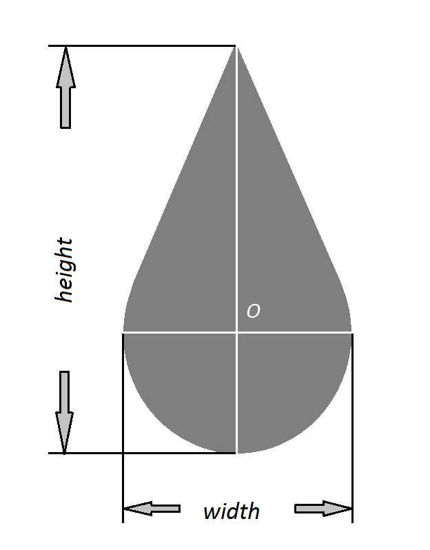
| tip |
The type of pen tip:
ellipse , rectangle , or
drop .
If ellipse , then the width property specifies the
horizontal diameter, and the height property specifies the vertical
diameter. If the height property is absent, its default value
is the value of width.
If rectangle , the width and height properties
specify the width and height of the rectangle. If the height
property is absent, the default value is the value of width making
the brush a square.
If drop , the shape is defined by a circle
and two tangent lines to a point outside the circle, located
above the circle on the vertical axis, as shown in F igure 4 . The width property is the
diameter the circle part, and the height property is the maximum
diameter of the shape.
Default is ellipse .
If the OR channel is present, the tip shape is rotated
counter-clockwise by this amount about its origin. |
| rasterOp |
A value that defines how the colors of
the pen and background interact. In the example images below,
the original background is white with the black text 'abc' and it
is overwritten with a single curved yellow ink stroke.
 |
noOperation specifies no
operation; the background is rendered without ink. |
 |
copyPen specifies that the
current pen color property is used and overwrites the
background. |
 |
maskPen specifies a combination
of the colors common to both the pen and the display. This
value simulates the effect of a highlighter pen. |
The default value is copyPen , which indicates
that the current pen color is used. Applications may define
additional rasterOp values. |
| antiAliased |
The drawn ink is anti-aliased.
Default is true. |
| fitToCurve |
The ink is rendered as a series of curves versus as
lines between pen sample points.
Default is false. |
| ignorePressure |
If true, pressure from the pen tip is ignored and
the width of the ink remains the same regardless of the pressure of
the pen on the tablet surface.
If false, the width of the ink gets wider with increased pressure
of the pen on the tablet surface.
Default is false. |
name = xsd:string
Name of property.
Required: yes
value = xsd:decimal | xsd:string
Value of named property.
Required: yes
units = xsd:string
Units used for value. If present, the
value must be a numeric property.
Required: no, Default: unknown
<brushProperty name="width" value="2" units="cm"/>
<brushProperty name="color" value="#FF0000"/>
4.4 Timestamps
Timestamping of traces is supported by the
<timestamp> element and the timestampRef
, timeOffset and duration attributes of the
<trace> element. For ease of processing, all
timestamps are expressed in milliseconds. Finer-grained timestamps
are obtained using fractional values.
4.4.1 <timestamp>
element
xml:id = xsd:ID
The identifier for this timestamp.
Required: yes
time = xsd:decimal
The absolute time for this timestamp, in
milliseconds since 1 January 1970 00:00:00 UTC.
Required: no, Default: none.
timestampRef = xsd:anyURI
The absolute time for this timestamp, given as
a reference to another timestamp.
Required: no, Default: none
timeString = xsd:dateTime
The absolute time for this timestamp, given in
a human-readable standard format.
Required: no, Default: none.
timeOffset = xsd:decimal
The relative time for this reference
timestamp, in milliseconds.
Required: No. Default. 0
EMPTY
The <timestamp> element establishes a
reference timestamp which can then be used for relative
timestamping of traces.
At most one of the attributes time , timestampRef
or timeString is used. The time thus given, plus the value
of the attribute timeOffset , gives the time value of the
timestamp.
If more than one of time , timeString and
timestampRef are given, then time is used if present.
Failing that, timeString is used.
If none of time , timestampRef or
timeString are given, then the timestamp refers to some
unspecified moment in time. This is useful when the timestamp is
referenced by multiple elements to provide relative timing
information.
The four examples below illustrate the establishment of various
reference timestamps. The first <timestamp>
element, ts001, refers to January 2, 2004 at 7:00am, UTC. The
second establishes timestamp ts002 which refers to January 2, 2004
at 7:10am, UTC (10 minutes after the reference timestamp ts001),
and the third time stamp, ts003, gives the same time using the
timeString attribute. The fourth creates ts004 with time
January 2, 2004 at 7:10:04.32, UTC (4.32 seconds after the
timestamp of trace ts002).
<timestamp xml:id="ts001" time="1073026800000"/>
<timestamp xml:id="ts002" timeOffset="600000" timestampRef="#ts001"/>
<timestamp xml:id="ts003" timeString="2004-01-02T07:10:00Z"/>
<timestamp xml:id="ts004" timeOffset="4320" timestampRef="#ts002"/>
4.5 The Default Context
Ink traces may specify their contexts explicitly, using a
contextRef attribute, or implicitly, in which case they use
a default context.
Explicitly referenced <context> elements may
occur in a <definitions> element, elsewhere in
the same document or in other documents. Explicit contexts are
typically used in archival ink applications.
Traces that do not make explicit reference to a context occur in
a default context. This is established by the sequence of elements
in the <ink> element. Initially the default
context is empty and uses defaults for all properties, including a
default trace format, default canvas, etc. Then, interspersed with
ink data, other elements may occur that alter the default context.
These elements are <brush> ,
<context> , <traceFormat> ,
<inkSource> and <timestamp> .
As the ink is processed from the first child onward, whenever one
of these elements is encountered, it is installed as the default to
be used by traces. These are used by traces that do not otherwise
specify these properties.
The default context may be explicitly specified using the URI "
#DefaultContext ". The id "
DefaultContext " is therefore
reserved and may not be used as the id of a user defined
<context> element.
4.6 Context Priority
To describe how contextual information is determined, we start
with the notions of "fully resolved context" and "current context"
as follows.
A fully resolved context is one for which all the context
information (brush, canvas, canvasTransform, inkSource, timestamp,
traceFormat) has been obtained either from direct children, by
references or inherited. Values are obtained for the context
information by giving the contents of the
<context> priority over specific references (
brushRef , canvasRef , canvasTransformRef ,
inkSourceRef , timestampRef , traceFormatRef
), which take priority over contextRef , which takes
priority over the current context.
The current context is a syntactic notion associated to
each node in an ink document. Roughly speaking, the current context
is changed only by <context> elements that occur
directly as children to the <ink> element (i.e.
not inside <definitions> ). It is defined as
follows.
- The first top-level child of an
<ink>
element has the default context its current context.
- If a top-level child of an
<ink> element has
a <context> element as its previous sibling,
then that context fully resolved is the child's current
context.
- If a top-level child has another kind of previous sibling, then
that sibling's current context is the child's current context.
- All descendants of a
<definitions> element
have the default context as their current context.
- All descendants of other kinds of top-level children have that
child's current context as their current context.
- All descendants of a top-level child have that child's current
context as their current context.
The current context is central to streaming ink applications
(see Streaming ).
We can now describe how contextual information is determined for
ink traces.
- For a top-level
<trace> ,
<traceGroup> or <traceView>
element (i.e. on that occurs as a direct child of an
<ink> element), a specific reference (
brushRef ) takes priority over contextRef which takes
priority over the current context. The resulting anonymous context
is the context of this node.
- For other
<trace> ,
<traceGroup> or <traceView>
elements, a specific reference ( brushRef ) takes priority
over contextRef which takes priority over the enclosing
<traceGroup> or <traceView>
node's context which takes priority over the current context. The
resulting anonymous context is the context of this node.
5 Canvases
InkML provides support for applications that are required to
combine ink from multiple sources. This may arise, for example,
from real-time collaboration among several devices, from multiple
ink annotations on the same base document or multiple pens
operating on the same surface. To support these applications, InkML
uses the concept of a shared space, called a canvas .
A canvas is specified using a <canvas>
element, and is typically referred to by one or more
<context> elements. These contexts may each have
their own set of ink capture characteristics and trace formats. In
order to map traces from a particular context to a canvas, and vice
versa, each context provides its own canvas transform, inverse
transform or both.
A context neither referencing nor inheriting a canvas uses a
default canvas, sufficient to allow simple single-canvas sharing
without further action on the part of devices or applications.
Each canvas defines its dimensions by giving a
<traceFormat> element. Its channel declarations
may specify minimum and/or maximum values, an orientation and
units. If no minimum or maximum is given for a channel of integer
or decimal type, then it is unbounded in that direction.
If a canvas is bounded in any direction, then all traces defined
on that canvas must be contained inside its limits. There may be
applications where strokes appear outside of the canvas. In these
cases the processing of out-of-bounds traces is not defined by the
specification.
Although canvases are virtual spaces, each of the coordinates
may be assigned a unit of measure. This allows collaborating
parties to establish a common notion of scale.
An example use for such a shared canvas might be a single ink
markup stream or file that contains traces captured on a tablet
computer, a PDA device, and an opaque graphics tablet attached to a
desktop computer. The size of these traces on each ink source and
corresponding display might differ, yet it may be necessary to
relate these traces to one another. They could represent scribbles
on a shared electronic whiteboard, annotations of a common
document, or the markings of two players in a distributed
tic-tac-toe game.
The trace data for these different ink sessions could be
recorded using the same set of virtual coordinates; however, it is
often useful, and may even be necessary at times, to record the
data in the ink source coordinates, in order to more precisely
represent the original capture conditions, for compactness, or to
avoid round-off errors that might be associated with the use of a
common coordinate system. Thus we define the concept of a "canvas
transform", which can vary according to the ink source. The default
transform is the identity. It is also possible to specify the
mapping from the canvas back to the coordinates of the original
trace format. This is useful in collaborative ink applications
where ink added to the canvas from one source must be interpreted
in the frame of reference of the other sources. It is not always
necessary to specify the inverse transform. If the canvas transform
is given as an affine map of full rank, then it may be inverted
numerically. Likewise if coordinates are transformed by a lookup
table with linear interpolation, then the mapping may be inverted
numerically. In all other cases the inverse transformation must be
provided if the inverse mapping is required.
5.1 <canvas> element
The <canvas> element provides the virtual
coordinate system, which uniquely identifies a shared virtual space
for cooperation of ink applications. Together with the
trace-to-canvas coordinate transform (discussed below), it provides
a common frame of reference for ink collected in multiple sessions
on different devices.
Attributes:
xml:id = xsd:ID
The unique identifier for this element.
Required: no, Default: none.
traceFormatRef = xsd:anyURI
A link to a <traceFormat>
element.
Required: no, Default: none.
Contents:
A <canvas> element must have an associated
<traceFormat> , which may either be given as a
child element or referred to by a traceFormatRef
attribute. If both a <traceFormat> element and a
traceFormatRef
attribute are specified, then the element overrides the attribute.
The coordinate space of the canvas is given by the regular channels
of the trace format and any intermittent channels are ignored.
Example:
<canvas xml:id="A4PaperCanvas">
   <traceFormat>
      <channel name="X" type="decimal" min="0" max="210" units="mm"/>
      <channel name="Y" type="decimal" min="0" max="297" units="mm"/>
   </traceFormat>
</canvas>
xml:id = xsd:ID
The identifier for this canvas transform.
Required: no, Default: none
invertible = xsd:boolean
Required: no, Default:
false
The <canvasTransform> element is used to
relate two coordinate systems. The source and target coordinate
systems are ultimately defined in terms of
<traceFormat> elements. These trace formats may
either be given directly, or indirectly by
<inkSource> , <context> or
other <canvas> elements. In general, the source
and target coordinate systems may involve a different number and
type of coordinates, or have different ranges and orientation for
the same dimension.
The contents of the <canvasTransform>
consists of one or two <mapping> elements.
If there is only one, then it is the mapping from the source to the
target coordinate system, where the meaning of "source" and
"target" is determined by the use. If there are two children, the
first is the mapping from the source to the target and the second
is the inverse mapping from the target back to the source.
The transform and its inverse need not be full inverses in the
mathematical sense. If a transform is from a trace format to a
canvas with fewer coordinates, then the inverse transform may map
from the canvas back to the original trace format by supplying
default values for the coordinates not in the canvas. This would
occur, for example, if a party were sharing ink from a device with
a force channel with a canvas with only spatial coordinates.
For certain classes of mappings, the inverse mapping may be
determined automatically. These are mappings of type "identity",
"affine" (for matrices of full rank), "table" (univariate, with
linear interpolation), and "product" mappings of these. In this
case, it is possible to specify that an inverse should be
determined automatically by giving only the forward transform and
specifying a value of true for the invertible
attribute. If two <mapping> elements are
specified, then the invertible attribute is
ignored.
For an application to give only the inverse transform, it should
supply the forward transform as an unknown mapping:
<canvasTransform>
   <mapping type="unknown"/>
   <mapping mappingRef="#map001"/>
</canvasTransform>
5.3 The Default Canvas
The default canvas has two real-valued coordinates X and Y, both
unbounded in the positive and negative directions. More precisely,
the default canvas is made available as though the following
element were included in each InkML document:
<canvas xml:id="DefaultCanvas">
   <traceFormat>
      <channel name="X"
               type="decimal" default="0" orientation="+ve" units="em"/>
      <channel name="Y"
               type="decimal" default="0" orientation="+ve" units="em"/>
   </traceFormat>
</canvas>
The default canvas may be explicitly specified using the URI "
#DefaultCanvas ". The id "
DefaultCanvas " is therefore reserved
and may not be used as the id of a user defined
<canvas> element.
6 Generics
This section describes components of the ink markup which are
applicable to multiple aspects of the ink markup.
6.1 Mappings
The <mapping> element provides a uniform
syntax for the various uses of mappings in the ink markup. The
element has an id attribute, which allows a particular
mapping to be applied in multiple places. When a previously defined
mapping is reused, the mappingRef attribute is used to refer
to the <mapping> element, which might be defined
in a <definitions> block. Mappings appear in the
following different places in InkML:
- In a
<channel> element of a
<traceFormat> , the <mapping>
element is used to describe the transformation from the values
actually produced by the device to the values recorded in the trace
data.
In a <crossCoupling> element, a
mapping can be used to specify the cross-coupling effect of one or
multiple channels on another channel. Used by a
<canvasTransform> , a mapping may be used to
specify the forward or inverse transformations between an ink
source and a canvas coordinate system.
InkML supports several types of mappings: unknown, identity,
lookup table, affine map, formula (specified using a subset of
MathML [ MATHML2 ]) and cross
product. The mapping type is indicated by the type attribute
of a <mapping> element. Note: If no mapping
appears for a <channel> , it defaults to
"unknown", which is safer than assuming that 'X' is identical to
the device's 'X' since some filtering or modifications could have
been applied. Furthermore, one can specify whether the results of a
mapping expression are absolute or relative to the current data
value. This is done by means of the apply attribute. For
lookup table mappings in particular, one can determine how to
interpret intermediate mapping values. This is specified using the
interpolation attribute.
Some points may have channel values that
cannot be mapped. These may lie outside the domain of a
MathML mapping (e.g. division by zero, arcsine of 7) or outside the
scope of a lookup table (e.g. below the lowest value when the
interpolation scheme is other than "ceiling"). In this situation
the behavior is not specified and may vary from implementation to
implementation. For example, an implementation may choose to
raise an error or omit the points.
6.1.1 <mapping>
element
xml:id = xsd:ID
The identifier for this mapping.
Required: no, Default: none
type = "identity" | "product" | "table" | "affine" |
"mathml" | "unknown"
The type for the particular mapping.
Required: no, Default: unknown
mappingRef = xsd:anyURI
The ID of a mapping which has previously been
defined.
Required: no, Default: none
(The mathml prefix above is declared as
"http://www.w3.org/1998/Math/MathML", the MathML schema namespace [
MATHML2 ].)
The identity map
If the type attribute has value
identity then the element is empty.
Identity mappings are specified using an empty mapping
element:
<mapping xml:id="m01" type="identity" />
<channel name="X" type="decimal" units="pt" default="0">
   <mapping type="identity"/>
</channel>
They are used, for example, to define a
<traceFormat> channel that reports the exact
data that is recorded by a corresponding device channel, with no
filtering or transformation.
Cross Product Maps
If the type attribute has value
product then the contents is a set of
<mapping> elements, each giving values for one
or more of the coordinates. This allows a multivariate mapping to
compute the different coordinate results according to the most
convenient means. For example, spatial coordinates may be
transformed using an affine map, button states by lookup tables,
and color coordinates using formulas.
Lookup Tables
If the type attribute has value
table then the mapping is a function specified by
a lookup table given as a <table> element
containing rows of values separated by commas.
Affine Maps
If the type attribute has value
affine then the content is an
<affine> element specifying an affine
transformation ( u ↦ M u + b )
from n source values to m target values. All of the
source and target values must be of the same type, either integer
or real (decimal or float). A matrix M containing only the
values 0, 1 and -1 may be used to perform arbitrary permutation and
reflection of coordinates. If the affine map computes a real number
for an integer coordinate, then the value is rounded to the nearest
integer.
MathML mappings
If the type attribute has value
mathml then the content is a subset of MathML [
MATHML2 ] restricted to the
following subset of Content MathML 2.0 elements:
This is a subset has been selected to provide expressions
suitable for scalar functions on integers, real numbers and boolean
values. A number of restrictions apply:
- The only elements permitted within the
<mathml:math> element are those in the above
list.
- The content of
<ci> and
<cn> elements is restricted to be text. In
particular, Presentation MathML markup is not allowed.
- The only attribute that is recognized is the type
attribute on the
<cn> element. The type
attribute may take the values integer ,
real or rational . Other attributes may
be given on elements, but they are ignored.
- All intermediate expressions must evaluate to an integer, real
or double value.
- Elements of the arithmetic, elementary classical functions,
logic and relations categories above may appear only as the first
child of an
<apply> element.
The content of The arithmetic operators return values whose type
depends on the type of the arguments. The logical operators and
relations return boolean values. The elementary functions return
real values.
Example: The following mapping converts from polar to
rectangular coordinates.
<mapping type="product">
   <mapping type="mathml">
      <bind target="X"/>
      <bind source="VR"  variable="r"/>
      <bind source="VTh" variable="theta"/>
      <math xmlns="http://www.w3.org/1998/Math/MathML">
         <apply>
            <times/>
            <ci>r</ci>
            <apply> <cos/> <ci>theta</ci> </apply>
         </apply>
      </math>
   </mapping>
   <mapping type="mathml">
      <bind target="Y"/>
      <bind source="VR"  variable="r"/>
      <bind source="VTh" variable="theta"/>
      <math xmlns="http://www.w3.org/1998/Math/MathML">
         <apply>
            <times/>
            <ci>r</ci>
            <apply> <sin/> <ci>theta</ci> </apply>
         </apply>
      </math>
   </mapping>
</mapping>
6.1.2 <bind> element
source = xsd:string
Specifies source data values and/or channel to
be considered in the mapping.
Required: no, Default: none
target = xsd:string
Specifies target data values and/or channel to
be considered in the mapping.
Required: no, Default: none
column = xsd:integer
Specifies the assigned column within a lookup
table either for source or target
channels.
channels or the assigned position for a
channel within the source or target vector of an affine
mapping.
Required: for lookup table bindings, bindings and
affine mappings , Default: none
variable = xsd:string
Specifies the variable within a formula that
represents the current source data/channel.
Required: for mathml bindings, Default: none
EMPTY
The <bind> element is provided for binding
channels to entities (variable names, lookup table columns) within
a mapping, and thus it supports the reuse of predefined mappings.
For each type of mapping, the relevant bindings can be expressed by
the combined usage of the <bind> element's
attributes, which are source , target , column
and variable .
For an identity mapping ( type="identity" ), if the
source channel has a different name than the channel being defined,
this can be specified using a <bind> element
with a source attribute. In the following markup, the
<traceFormat> channel X contains unmanipulated
data from the device's devX channel. When the mapping
type is an identity mapping, the <bind> element
source attribute is required, and the other
attributes target , column , and
variable must not be present.
<channel name="X">
   <mapping type="identity">
      <bind source="devX"/>
   </mapping>
</channel>
Within a mapping formula ( type="mathml" ), the variable
names in the formula need to be bound to particular channel names.
This is specified using a combination of source and
variable attributes for binding inputs of the formula, and
target and variable for the output of the formula.
This is useful if the same mapping formula is to be reused across
multiple channels, like X and Y for example. When the mapping
type is an mathml mapping the column attribute for
the <bind> element must not be present.
<mapping xml:id="m06" type="mathml">
   <bind target="X" variable="Q" />
   <math xmlns="http://www.w3.org/1998/Math/MathML">
      <apply>
         <plus/>
         <ci>Q</ci>
         <cn>10</cn>
      </apply>
   </math>
</mapping>
The example shown above means that the channel X is referred to
by the variable name Q in the mapping expression "Q+10".
For a lookup table ( type="table" ), each index column
must be bound to the channel that provides the input for the lookup
operation. This is done with a <bind> element
that specifies source and column attributes.
Similarly, each value column must be bound to the channel that
receives the output of the lookup. Its <bind>
element specifies target and column .
When the mapping type is a lookup mapping the
variable attribute for the
<bind> element must not be present.
The following example indicates assignments of channels to
columns. It means that values for the channels OTx and P are used
to look up the value of the cross-coupling for channel X in the
table given by the mapping below:
<mapping xml:id="m07" type="table">
   <bind target="X" column="1"/>
   <bind source="OTx" column="2"/>
   <bind source="P" column="3"/>
   <table apply="relative" interpolation="floor">
      10    45    512,
      9     45    400,
      8     45    372,
      7     45    418,
      10    50    510,
      9     50    403,
      8     50    302,
      7     50    407,
      10    55    512,
      9     55    410,
      8     55    303,
      7     55    405,
      10    60    512,
      9     60    420,
      8     60    355,
      7     60    401,
   </table>
</mapping>
For an affine mapping ( type="affine" ), the column values give the meaning of the rows
and columns of the transformation matrix. Suppose an affine mapping
is specified by the augmented matrix (M b), corresponding to the
transformation v = M . u + b. Then a <bind> element with a source attribute will have a column attribute specifying which index in the vector u
corresponds to the named source channel. Likewise, a
<bind> element with a target attribute will have a column attribute specifying which index in the vector v
corresponds to the named target channel. If the target bindings are
the same as the source bindings, then they may be
omitted.
6.1.3 <table> element
xml:id = xsd:ID
The unique identifier for this
table element.
Required: no
apply = "absolute" | "relative"
Specifies whether the mapping values are used
from the table/formula, or whether this table/formula needs to be
added to the current data value.
Required: no, Default: absolute
interpolation = "floor" | "middle" | "ceiling" | "linear" |
"cubic"
Specifies the interpolation between discrete
mapping values defined by a lookup table.
Required: no, Default: "linear"
((number | "T" | "F")+ ",")* (number
| "T" | "F")*
where number is defined by the grammar given in the
<trace> element
section.
The <table> gives a set of points for a
mapping. The points are given as comma-separated rows. Each row
must have the same number of entries. The final row may optionally
be followed by a comma. Each row in the table represents a value of
the function at one point. Which columns represent the argument(s)
and which the result(s) is determined by <bind>
elements.
The entries in the table may either be all numerical or all
boolean. They may be derived empirically, by measuring properties
of a device, calculated to provide efficient approximation to a
numerical function, or give an exhaustive enumeration of values of
a function over a finite set of values.
Example:
The following example means that X is a function of OE, given by
a lookup table. The value "relative" for the apply , means
the table gives an amount to increase X.
<channel name="X"...>
   ...
   <mapping xml:id="m03" type="table">
      <bind source="OE"/>
      <bind target="X"/>
      <table apply="relative" interpolation="floor">
         45  10,
         50   9,
         55   8,
         60   7
      </table>
   </mapping>
   ...
</channel>
Tables may have more than two columns, with some of them (the
source columns) determining others (the target columns). If there
is more than one source column, then all possible combinations of
source values must be given. For example, if there are two source
columns with one having 3 distinct values and the other having 5
distinct values, then the table must have 15 rows.
The value of the interpolation attribute defines the
behavior for indices that don't appear in a numerical table. The
following summarizes the behavior of the above table for the
various values of interpolation :
| "floor" |
The value is determined by rounding all source variables down
to the nearest specified value.
X += 10  if 45 ≤ OE < 50,
X += 9   if 50 ≤ OE < 55,
...
|
| "middle" |
The value is constant on regions whose boundaries are mid-way
between the given source values.
X += 10  if 45   ≤ OE < 47.5,
X += 9   if 47.5 ≤ OE < 52.5,
...
|
| "ceiling" |
The value is determined by rounding all source variables up to
the nearest specified value.
X += 10  if      OE ≤ 45,
X += 9   if 45 < OE ≤ 50,
...
|
| "linear" |
Piece-wise linear interpolation. |
| "cubic" |
Interpolation by cubic splines. This option may be used only
for univariate mappings and requires the table have at least 4
points. |
The interpolation attribute may not be used with boolean
tables.
6.1.4 <affine>
element
xml:id = xsd:ID
The unique identifier for this
<affine> element.
Required: no
( number+ ",")* number*
where number is defined by the grammar given in the
<trace> element
section.
The <affine> element provides the entries for
an affine mapping from n source values to m target
values. An affine mapping consists of a linear transformation
(multiplication by a matrix) and a shift (adding a vector). The
content of the <affine> element is text giving a
m comma-separated rows of n+1 numbers each. The final
row may optionally be followed by a comma. The first n
columns specify an m ×n matrix M , and the last
column gives a vector b of length m . If u is
the source vector of n coordinates, then v = M u +
b is the target vector of m coordinates.
The following is an example of an affine mapping using an
<affine> element to describe the transform (X,
Y) ↦ (-Y, X+200).
 <mapping xml:id="m01" type="affine">
   <bind target="X" />
   <bind target="Y" />

   <bind source="X" column="1"/>
   <bind source="Y" column="2"/>

   <affine>
      0 -1   0,
      1  0 200,
   </affine>
</mapping>
6.2 Definitions
6.2.1 <definitions>
element
none
The <definitions> element is a container
which is used to define reusable content. The definitions within a
<definitions> block can be referenced by other
elements using the appropriate syntax. Content within a
<definitions> block has no impact on the
interpretation of traces, unless referenced from outside the
<definitions> block. In order to allow them to
be referenced, elements within a <definitions>
block must include an id ; attribute. Therefore, an element
which is defined inside a <definitions> without
an id , or that is never referenced, serves no purpose.
One of the primary uses of <definitions> is
to define contextual information. In particular, the elements
<brush> , <canvas> ,
<canvasTransform> , <context>
, <inkSource> , <mapping> ,
<timestamp> and <traceFormat>
may be given inside a <definitions> . These may
be referenced from other elements by the attributes brushRef
, canvasRef , canvasTransformRef , contextRef
, inkSourceRef , mappingRef , timestampRef and
traceFormatRef , respectively. Timestamps may also be
referenced by the respectTo attribute of the
<channel> element.
Another use of <definitions> is to define
digital ink traces for later reference. These may be given by
<trace> , <traceGroup> or
<traceView> . These are not considered part of
the ink data to be handled by the application until they are
referenced from other elements (outside the
<definitions> ) by a traceDataRef
attribute. This is useful in archival applications.
The following simple example illustrates usage of the
<definitions> element.
<ink xmlns="http://www.w3.org/2003/InkML">
   <definitions>
      <brush xml:id="redPen"/>
      <brush xml:id="bluePen"/>
      <traceFormat xml:id="normal"/>
      <traceFormat xml:id="noForce"/>
      <context xml:id="context1"
            brushRef="#redPen"
            traceFormatRef="#normal"/>
      <context xml:id="context2"
            contextRef="#context1"
            brushRef="#bluePen"/>
   </definitions>
   <context contextRef="#context2" traceFormatRef="#noForce"/>
   <context xml:id="context3"/>
</ink>
More details on the usage of the
<definitions> element are provided in the Archival Applications section.
6.3 Annotations
InkML provides generic ways of assigning metadata or semantics
to ink via two elements <annotation> and
<annotationXML> , modeled after the
corresponding elements in MathML. However since annotations are
typically application-specific, InkML does not attempt to prescribe
the contents of these elements. Since the contents of
<annotation> or
<annotationXML> elements are application
defined, implementers should use them with care and remain aware
that other implementations may ignore them or fail to round-trip
unrecognized annotations.
6.3.1 <annotation>
element
type = xsd:string
The category of annotation that this element
describes, for descriptive purposes only. (Applications may define
their own types.)
Required: no
Default: none
encoding = xsd:string
The kind of syntax, standard or convention
being used for the values of the annotation, e.g. ISO639 for
language codes. Required: no
Default: none
Other attributes in a namespace other than that of InkML are
also allowed, such as general metadata properties (e.g. from the
Dublin Core vocabulary) or application-specific attributes.
The <annotation> element provides a mechanism
for inserting simple textual descriptions in the ink markup. This
may be used for multiple purposes. For instance, the text contained
in the <annotation> may include additional
information provided by the user generating InkML, and may be
displayed by an InkML consumer rendering a graphical representation
of traces. Or it may be used for the indication of metadata such as
the writer, the writing instrument. Another important potential
application is the semantic tagging of traces.
<ink xmlns="http://www.w3.org/2003/InkML"
     xmlns:dc="http://dublincore.org/documents/2001/10/26/dcmi-namespace/">
   <annotation type="description">A Sample of Einstein's Writings</annotation>
   <annotation type="writer">Albert Einstein</annotation>
   <annotation type="contentCategory">Text/en</annotation>
   <annotation type="language" encoding="ISO639">en</annotation>
   <annotation dc:language="en"/>
   <trace xml:id="trace1">
      ...
   </trace>
   <traceGroup xml:id="tg1">
      <annotation type="truth">Hello World</annotation>
      <traceGroup>
         <annotation type="truth">Hello</annotation>
         <trace> ...  </trace>
         ...
      </traceGroup>
      <traceGroup>
         <annotation type="truth">World</annotation>
         <trace> ...  </trace>
         ...
     </traceGroup>
   </traceGroup>
   <traceView traceDataRef="#tg1"/>
</ink>
For semantic tagging, one of the common types of
<annotation> is "contentCategory", which
describes at a basic level the category of content that the traces
represent; e.g., "Text/English", "Drawing", "Math", "Music". Such
categories are useful for general data identification purposes, and
may be essential for selecting data to train handwriting
recognizers in different problem domains.
Although largely application-defined, a number of likely, common
categories are suggested below.
- Text/<language>[/<script>][/<sub-category>]
(e.g., Text/jpn/Kanji, Text/en/SSN)
- Drawing[/<sub-category>] (e.g., Drawing/Sketch,
Drawing/Diagram)
- Math
- Music
- Chemistry[<sub-category>]
The language specification may be made using any of the language
identifiers specified in ISO 639, using 2-letter codes, 3-letter
codes, or country names. Some text may also require a script
specification (such as Kanji, Katakana, or Hiragana) in addition to
the language.
For some applications it may be useful to provide additional
sub-categories defining the type of the data. For example, some
suggested sub-categories for Text include:
- SSN (Social Security Number)
- Phone
- Date
- Time
- Currency
- URL
Suggested possible sub-categories for Drawing are:
- Sketch (Not suitable for geometric clean-up)
- Diagram (Suitable for geometric clean-up)
6.3.2
<annotationXML> element
type = xsd:string
The category of annotation that this element
describes, for descriptive purposes only. (Applications may define
their own types.)
Required: no, Default: none
encoding = xsd:string
The kind of syntax, standard or convention
being used for the values of the annotation, e.g. ChemML, MathML,
RDF, etc.
Required: no, Default: none
href = xsd:anyURI
A reference to XML content giving the
annotation. Required: no, Default: none
Other attributes in a namespace other than that of InkML are
also allowed, such as general metadata properties (e.g. from the
Dublin Core vocabulary) or application-specific attributes.
Any XML-based annotation
This element allows ink to be annotated with general XML
objects. For instance a handwritten equation may be described using
a snippet of MathML, or metadata and semantic annotation may be
provided using an XML language. These annotations may be given
either as the content of an <annotationXML>
element or may be referred to by a href attribute, but
not both. If several annotations are desired, several
<annotationXML> elements should be given.
When annotations of a parent node include the content of the
annotations of the child nodes, then one should consider using
<annotationXML> annotations on the children with
href attributes referring to sub-trees of the parents
annotation in order to maintain linear space complexity in the
annotations.
<ink xmlns="http://www.w3.org/2003/InkML">
   <annotation type="description">A Sample of Einstein's Writings</annotation>
   <annotationXML type="metadata" encoding="rdf">
      <rdf:RDF xmlns:rdf="http://www.w3.org/1999/02/22-rdf-syntax-ns#"
               xmlns:dc="http://purl.org/dc/elements/1.1/" >
         <rdf:Description about=""
            dc:language="en"
            dc:date="2004-04-11"
            dc:creator="InkML Maker v0.1"
            dc:publisher="Famous Handwritings Ltd."/>
      </rdf:RDF>
   </annotationXML>
   <trace> ... </trace>
   ...
   <trace> ... </trace>
</ink>
<ink xmlns="http://www.w3.org/2003/InkML">
   <annotationXML type="truth" encoding="application/xhtml+xml">
      <html xmlns="http://www.w3.org/1999/xhtml">
         <body>
            <div xml:id="Ch1">
               <h1 xml:id="T1"><span xml:id="W1">Weather </span></h1>
               <p xml:id="P1">
                 <span xml:id="W2">The</span>
                 <span xml:id="W3">rain</span>
                 ... more words
               </p>
               <p xml:id="P2">...</p>
               ... more paragraphs
            </div>
            ... more chapters
         </body>
      </html>
   </annotationXML>
   <traceGroup>
      <annotationXML href="#Ch1"/>
      <traceGroup>
         <annotationXML href="#T1"/>
         <traceGroup>
            <!-- Weather -->
            <annotationXML href="#W1"/>
            <trace>...</trace>
         </traceGroup>
      </traceGroup>
      <traceGroup>
         <annotationXML href="#P1"/>
         <traceGroup>
            <!-- The -->
            <annotationXML href="#W2"/>
            <trace>...</trace>
         </traceGroup>
         <traceGroup>
            <!-- rain -->
            <annotationXML href="#W3"/>
            <trace>...</trace>
         </traceGroup>
         ... more words in paragraph
      </traceGroup>
   </traceGroup>
   <traceGroup>
       <annotationXML href="#P2"/>
       ... words in paragraph
   </traceGroup>
   ... more paragraphs in chapter.
</ink>
If it were not for the sharing of the substructure of the
attribute XML data, then each attribute word would be repeated
three times (as a word, in a paragraph, and in a chapter), each
paragraph would be repeated twice, etc.
6.4 Units
Units are used in several parts of ink mark up. For example
channels may report their values with some dimension, such as
length, requiring units. Other elements may give values, such as
resolution, as quantities in particular units.
The following abbreviations must be recognized as unit attribute
values.
| Dimension |
Unit |
Interpretation |
| length |
m |
meters |
| |
cm |
centimeters |
| |
mm |
millimeters |
| |
in |
inches |
| |
pt |
points (1pt = 1/72 in) |
| |
pc |
picas (1pc = 1/22 pt) |
| |
em |
ems, the width of a letter "M" in a notional normal size |
| |
ex |
exs, the height of a letter "x" in a notional normal size |
| time |
s |
seconds |
| |
ms |
milliseconds |
| mass |
kg |
kilograms |
| |
g |
grams |
| |
mg |
milligrams |
| force |
N |
Newtons |
| angle |
deg |
degrees |
| |
rad |
radians |
| all |
% |
percentage, expressed as a fraction (1.0 = 100%) relative to
max-min |
| |
dev |
quanta relative to a device resolution. This can correspond to
pixels, force levels, clock ticks, etc. |
In addition to the units named above, the following expressions
must also be recognized:
unitExpr ::=
      unit
    | "1"      "/" unit
    | unitExpr "/" unit
    | unitExpr "*" unit
unitPrimitive ::= unit | "(" unitExpr ")"
unit ::= one of the units from the table above,
         with the exception of em, ex, % and dev.
Other units are permitted, but need not be recognized by a
compliant application.
7 Archives and Streams
The ink markup is expected to be used in many different
scenarios. Ink markup data may be transmitted in substantially real
time while exchanging ink messages, or ink documents may be
archived for later retrieval or processing. InkML has been designed
with both of these uses in mind, and it is natural to use InkML in
a particular way in each of these settings.
These settings illustrate two different styles of ink generation
and usage. In the later, the markup must facilitate the incremental
transmission of a stream of ink data, while in the former, the
markup should provide the structure necessary for operations such
as search and interpretation. In order to support both cases, InkML
provides archival and streaming modes of usage. These are not
distinct and incompatible languages, but rather are two stylized
ways of using InkML.
7.1 Archival Applications
Archival applications typically handle ink data that has been
collected over some span of time and has some structure,
organization or interpretation associated to the ink data. These
applications may re-organize ink traces so it is preferable that
the traces be state-free. That is, in archival applications, to the
extent that ink traces make use of context information, this is
always done explicitly and never through the "current" context.
In archival usage, contextual elements occur within one or more
<definitions> elements and are assigned
identifiers using the id attribute. References to defined elements
are made using the corresponding brushRef ,
traceFormatRef , and contextRef attributes. This is
illustrated in the following example:
<definitions>
   <brush xml:id="penA"/>
   <brush xml:id="penB"/>
   <traceFormat xml:id="fmt1">
      <channel name="X" type="integer"/>
      <channel name="Y" type="integer"/>
      <channel name="Z" type="integer"/>
   </traceFormat>
   <canvas xml:id="canvasA">
      <traceFormat>
         <channel name="X" type="decimal" min="0" max="200" units="mm"/>
         <channel name="Y" type="decimal" min="0" max="150" units="mm"/>
      </traceFormat>
   </canvas>
   <canvasTransform xml:id="trans1">
      <mapping type="affine">1 0 0 0,0 1 0 0</mapping>
   </canvasTransform>
   <canvasTransform xml:id="trans2">
      <mapping type="affine">2 0 0 0,0 -2 0 0</mapping>
   </canvasTransform>
   <context xml:id="context1"
      canvasRef="#canvasA"
      canvasTransformRef="#trans1"
      traceFormatRef="#fmt1"
      brushRef="#penA"/>
   <context xml:id="context2"
      canvasRef="#canvasA"
      canvasTransformRef="#trans2"
      traceFormatRef="#fmt1"
      brushRef="#penB"/>
</definitions>
This example defines two brushes ("penA" and "penB"), a
traceFormat ("fmt1"), and two contexts ("context1" and "context2")
which both refer to the same canvas ("canvasA") and traceFormat
("fmt1"), but with different canvas transforms and brushes. Note
the use of the brushRef , traceFormatRef ,
canvasRef and canvasTransformRef attributes to refer
to previously defined <brush> ,
<traceFormat> <canvas> and
<canvasTransform> elements.
Within the scope of a <definitions> element,
unspecified attributes of a <context> element
are assumed to have their default values. The
<definitions> block below defines "context1",
which is comprised of "canvasA" with the default canvasTransform
and traceFormat (the identity mapping and a traceFormat consisting
of decimal X-Y coordinate pairs), and "penA".
 <definitions>
    <brush xml:id="penA"/>
    <context xml:id="context1"
      canvasRef="#canvasA"
      brushRef="#penA"/>
</definitions>
A <context> element can inherit and override
the values of a previously defined context by including a
contextRef attribute, so the following block defines "context2"
which shares the same canvas ("canvasA") and traceFormat (the
default format) as "context1", but has a different canvasTransform
and brush.
<definitions>
   <brush xml:id="penA"/>
   <context xml:id="context1"
      canvasRef="#canvasA"
      canvasTransformRef="#trans1"/>
   <context xml:id="context2"
      contextRef="#context1"
      canvasTransformRef="#trans2"
      brushRef="#penA"/>
</definitions>
Within archival ink markup, traces can either explicitly specify
their context through the use of contextRef and brushRef
attributes, or they can have their context provided by an enclosing
traceGroup. In the following example, traces "t001" and "t003" have
the context defined by "context1", while trace "t002" has a context
consisting of the default canvas, canvasTransform and traceFormat,
and "penA".
<trace xml:id="t001" contextRef="#context1">...</trace>
<trace xml:id="t002" brushRef="#penA">...</trace>
<traceGroup contextRef="#context1">
   <trace xml:id="t003">...</trace>
</traceGroup>
Traces within a <traceGroup> element can also
override the context or brush specified by the traceGroup. In the
following example, traces "t001" and "t003" have their context
specified by "context1" while trace "t002" overrides the default
brush of "context1" with "penA".
<traceGroup contextRef="#context1">
   <trace xml:id="t001">...</trace>
   <trace xml:id="t002" brushRef="#penA">...</trace>
   <trace xml:id="t003">...</trace>
</traceGroup>
A trace or traceGroup can both reference a context and override
its brush, as in the following example which assigns the context
specified by "context1" to traces "t001" and "t002", but with
"penA" instead of the default brush.
<trace xml:id="t001" contextRef="#context1" brushRef="#penA">...</trace>
<traceGroup contextRef="#context1" brushRef="#penA">
    <trace xml:id="t002">...</trace>
</traceGroup>
In archival mode, the ink markup processor can straightforwardly
determine the context for a given trace by examining only the
<definitions> blocks within the markup and the
enclosing traceGroup for the trace.
7.2 Streaming Applications
Streaming ink applications present digital ink traces in
sequential time order. Contextual information is inserted into the
stream of ink traces, as needed, to provide interpretation for the
ink strokes. These changes to the current trace context are given
by <context> elements. These may directly
contain brush, trace format and other information or which may
refer to previously seen such elements. This corresponds to an
event-driven model of ink generation, where events which result in
contextual changes map directly to elements in the markup.
The current context consists of the set of canvas,
canvasTransform, traceFormat and brush which are associated with
subsequent traces in the ink markup. Initially, the current context
contains the default canvas, an identity canvasTransform, the
default traceFormat, and a brush with no attributes. Each
<brush> , <traceFormat> , and
<context> element which appears outside of a
<definitions> element changes the current
context accordingly (elements appearing within a
<definitions> block have no effect on the
current context, and behave as described above in the archival
section).
The appearance of a <brush> element in the
ink markup sets the current brush attributes, leaving all other
contextual values the same. Likewise, the appearance of a
<traceFormat> element sets the current
traceFormat, and the appearance of a <context>
element sets the current context.
Outside of a <definitions> block, any values
which are not specified within a <context>
element are taken from the current context. For instance, the
<context> element in the following example
changes the current brush from "penB" to "penA", leaving the
canvas, canvasTransform, and traceFormat unchanged from trace
"t001" to trace "t002". That is, each context element is taken to
inherit from the previously established context.
<brush xml:id="penA"/>
<brush xml:id="penB"/>
<trace xml:id="t001">...</trace>
<context brushRef="#penA"/>
<trace xml:id="t002">...</trace>
In order to change a contextual value back to its default value,
its attribute can be specified with the value "
#DefaultCanvas " or "
#DefaultBrush ". In the following:
<context canvasRef="#canvasA" brushRef="#penA"/>
<trace xml:id="t001">...</trace>
<context canvasRef="#DefaultCanvas" brushRef="#DefaultBrush"/>
<trace xml:id="t002">...</trace>
Trace "t001" is on "canvasA" and has the brush specified by
"penA", while trace "t002" is on the default canvas and has the
default brush.
Brushes, traceFormats, and contexts which appear outside of a
<definitions> block and contain an id
attribute both set the current context and define contextual
elements which can be reused (as shown above for the brushes "penA"
and "penB"). This example:
<context xml:id="context1"
    canvasRef="#canvasA"
    canvasTransformRef="#trans1"
    traceFormatRef="#fmt1"
    brushRef="#penA"/>
defines a context which can be referred to by its identifier
"context1". It also sets the current context to the values
specified in the <context> element.
A previously defined context is referenced using the
contextRef attribute of the <context>
element. For example:
<context contextRef="#context1"/>
sets the current context to have the values specified by
"context1". A <context> element can also
override values of a previously defined context by including both a
contextRef attribute and one or more of the canvasRef
, canvasTransformRef , traceFormatRef or
brushRef attributes. The following:
<context contextRef="#context1" brushRef="#penB"/>
sets the current context to the values specified by "context1",
except that the current brush is set to "penB" instead of
"penA".
A <context> element which inherits and
overrides values from a previous context can itself be reused, so
the element:
<context xml:id="context2" contextRef="#context1" brushRef="#penB"/>
defines "context2" which has the same context values as
"context1" except for the brush.
Finally, a <context> element with only an id
has the effect of taking a "snapshot" of the current context which
can then be reused. The element:
<context xml:id="context3"/>
defines "context3", whose values consist of the current
canvasRef, canvasTransform, traceFormat, and brush at the point
where the element occurs (note that since "context3" does not
specify any values, the element has no effect on the current
context).
An advantage of the streaming style is that it is easier to
express overlapping changes to the individual elements of the
context. However, determining the context for a particular trace
can require more computation from the ink markup processor, since
the entire file may need to be scanned from the beginning in order
to establish the current context at the point of the
<trace> element.
While it is possible to wait and generate each trace as it is
completed, this can lead to considerable latency from the starting
time with long strokes. This may be avoided by generating
traces of partial strokes and using continuation traces.
Finally, it should be noted that traces can overlap in
time. This can occur in collaborative applications with
several writers or with one user on "multi-touch" devices.
Here it is also possible to generate traces for complete strokes on
pen up, but applications may use partial strokes of limited time
duration to guarantee that a buffer restricted to a sliding time
window sees all simultaneous traces.
7.3 Archival and Streaming Equivalence
The following examples of archival and streaming ink markup data
are equivalent, but they highlight the differences between the two
styles:
Archival
<ink xmlns="http://www.w3.org/2003/InkML">
   ...
   <definitions>
      <brush xml:id="penA"/>
      <brush xml:id="penB"/>
      <context xml:id="context1"
         canvasRef="#canvas1"
         canvasTransformRef="#trans1"
         traceFormatRef="#format1"/>
      <context xml:id="context2"
         contextRef="#context1"
         canvasTransformRef="#trans2"/>
   </definitions>
   <traceGroup contextRef="#context1">
        <trace>...</trace>
        ...
   </traceGroup>
   <traceGroup contextRef="#context2">
        <trace>...</trace>
        ...
   </traceGroup>
   <traceGroup contextRef="#context2" brushRef="#penB">
        <trace>...</trace>
        ...
   </traceGroup>
   <traceGroup contextRef="#context1" brushRef="#penB">
        <trace>...</trace>
        ...
   </traceGroup>
   <traceGroup contextRef="#context1" brushRef="#penA">
        <trace>...</trace>
        ...
   </traceGroup>
</ink>
Streaming
<ink xmlns="http://www.w3.org/2003/InkML">
   ...
   <definitions>
      <brush xml:id="penA"/>
      <brush xml:id="penB"/>
   </definitions>
   <context xml:id="context1"
      canvasRef="#canvas1"
      canvasTransformRef="#trans1"
      traceFormatRef="#format1"/>
   <trace>...</trace>
   ...
   <context xml:id="context2"
      contextRef="#context1"
      canvasTransformRef="#trans2"/>
   <trace>...</trace>
   ...
   <context brushRef="#penB"/>
   <trace>...</trace>
   ...
   <context contextRef="#context1"/>
   <trace>...</trace>
   ...
   <context brushRef="#penA"/>
   <trace>...</trace>
   ...
</ink>
In the archival case, the context for each trace is simply
determined by the <trace> element, its enclosing
traceGroup, and contextual elements defined in the
<definitions> block, while in the streaming
case, the context for a trace can depend on the entire sequence of
context changes up to the point of the <trace>
element.
However, the streaming case more simply expresses the changes of
context involving "penB", "context1", and "penA", whereas the
archival case requires the restatement of the unchanged values in
the successive traceGroups.
The two styles of ink markup are equally expressive, but impose
different requirements on the ink markup processor and generator.
Tools to translate from streaming to archival style might also be
of use to applications which work on stored ink markup.
8. Conformance
The contents of this section are normative.
8.1 Conforming InkML Documents
A document is a Conforming InkML Document if it meets both the
following conditions:
- It is a well-formed XML document [ XML ]
conforming to Namespaces in XML [ XMLNS
].
- It adheres to the specification described in this document
(InkML Specification) including the constraints expressed in the
Schema (see Appendix E ) and having an XML
Prolog and root element as specified in Section 2.1 .
The InkML specification and these conformance criteria provide
no designated size limits on any aspect of InkML documents. There
are no maximum values on the number of elements, the amount of
character data, or the number of characters in attribute
values.
Within this specification, the term URI refers to a
Universal Resource Identifier as defined in [ RFC3986 ] and extended in [ RFC3987 ] with the new name IRI. The term URI
has been retained in preference to IRI to avoid introducing new
names for concepts such as "Base URI" that are defined or
referenced across the whole family of XML specifications
.
8.2 Using InkML with other Namespaces
The InkML namespace is intended to be used with other XML
namespaces as per the Namespaces in XML Recommendation [ XMLNS ]. Future work by W3C is expected to
address ways to specify conformance for documents involving
multiple namespaces.
8.3 Conforming InkML Processors
An InkML processor is a program that can process and/or generate
Conforming InkML documents.
In a Conforming InkML Processor, the XML parser MUST be able to
parse and process all XML constructs defined by XML 1.1 [ XML ] and Namespaces in XML [ XMLNS ]. It is not required that a Conforming
InkML Processor uses a validating XML parser.
A Conforming InkML Processor MUST correctly understand and apply
the semantics of each markup element or attribute as described by
this document.
There is, however, no conformance requirement with respect to
performance characteristics of the InkML Processor. For instance,
no statement is required regarding the accuracy, speed or other
characteristics of output produced by the processor. No statement
is made regarding the size of input that a InkML Processor is
required to support.
A Acknowledgements
We thank our colleagues at IBM for providing their work in 2002
as a starting point for this definition.
We thank all participants in the InkML activity of the
Multimodal Interaction Working Group for the many detailed
constructive discussions. Without the participants' desire to
obtain the best outcome, regardless of corporate affiliation, this
work would not have been possible.
We specifically thank the W3C staff who have supported the InkML
activity: Max Froumentin who served as a staff member of W3C until
2006 and served as editor of previous working drafts and Kazuyuki
Ashimura who then took responsibility for the InkML activity at W3C
and has provided continuous energy and support.
Finally, we thank Deborah Dahl, whose stewardship of the W3C
Multimodal Interaction Working Group has provided the perfect
environment for this work to come to fruition.
B Implementation Guidelines
The following are informative implementation guidelines for
reducing InkML file size and environmental interactions.
- Gzip compression.
The lossless gzip compression [ RFC1952 ] will help to reduce the InkML
file size considerably. It is recommend that applications
have the facility to compress and decompress InkML files and
streams using the gzip algorithm.
The lossless gzip compression [ RFC1952 ] will help to reduce the InkML
file size
- Authoring tips
The elements which define constructs that can be
referenced repeatedly such as <brush>
definitions, and <traceFormat> definitions
should be placed within a <definition> element and
referred to in required places such as <trace> elements.
Applications should take advantage of trace data
prefixes (' | " | *) for defining relative coordinate values.
The use of first and second order derivative coordinates can
effectively compress <trace> element data
losslessly.
Applications should make use of the 'current
context' to cache the context property values and hence reduce the
context property markups that are being sent explicitly along with
trace data.
- InkML transmission
Any of the usual XML protocols (StAX, SOAP, etc)
may be used to transmit InkML documents or fragments between
subprograms or distributed programs.
- Network streaming
Client and server applications that wish to
stream InkML should have the capability to process the data sent in
multiple fragments of InkML packets. The receipt of such
InkML fragments may progressively render on the client or
clients.
C References
- [DC]
- Dublin
Core Metadata Element Set, Version 1.1: Reference
Description . http://dublincore.org/documents/dces/
.
- [RDF-SYNTAX]
- RDF/XML
Syntax Specification (Revised) , D. Beckett, Editor, W3C
Recommendation, 10 February 2004,
http://www.w3.org/TR/2004/REC-rdf-syntax-grammar-20040210/ . Latest version
available at http://www.w3.org/TR/rdf-syntax-grammar/ .
- [RFC1952]
- GZIP file
format specification version 4.3 . IETF RFC 1952.
http://www.ietf.org/rfc/rfc1952.txt .
- [RFC3023]
- XML Media
Types . IETF RFC 3023.
http://www.ietf.org/rfc/rfc3023.txt .
- [XML]
Tim Bray et al., editors. Extensible
Markup Language (XML) 1.1 . World Wide
Web Consortium, (Second
Edition) ,
Tim Bray et al., Editors, W3C
Recommendation,
2004.
16 August 2006,
http://www.w3.org/TR/2006/REC-xml11-20060816/ . Latest
version
available at http://www.w3.org/TR/xml11/
.- [XMLNS]
Tim Bray et al. , editors .
Namespaces
in XML 1.1 , World Wide Web
Consortium, (Second
Edition) ,
Tim Bray et al., Editors, W3C
Recommendation,
200 6 .
16 August 2006,
http://www.w3.org/TR/2006/REC-xml-names11-20060816/ . Latest version
available at
http://www.w3.org/TR/xml-names11/ .- [XMLSCHEMA2]
- XML
Schema Part 2: Datatypes Second
Edition , A. Malhotra, P. V. Biron,
Editors, W3C Recommendation,
2 May 2001,
http://www.w3.org/TR/2001/REC-xmlschema-2-20010502/
28 October 2004,
http://www.w3.org/TR/2004/REC-xmlschema-2-20041028/ . Latest version
available at
http://www.w3.org/TR/xmlschema-2/ .
- [MATHML2]
- Mathematical
Markup Language (MathML) Version 2.0 (Second Edition) ,
David Carlisle, Patrick Ion, Robert Miner, Nico Poppelier, Editors,
W3C Recommendation, 21 October 2003,
http://www.w3.org/TR/2003/REC-MathML2-20031021/ . Latest version
http://www.w3.org/TR/MathML2/ .
- [RFC3986]
- Uniform
Resource Identifier (URI): Generic Syntax. IETF RFC
3986. http://www.ietf.org/rfc/rfc3986.txt, January 2005
- [RFC3987]
- Internationalized
Resource Identifiers (IRIs). IETF RFC 3987,
http://www.ietf.org/rfc/rfc3987.txt, January 2005.
- [EBNF]
-
Information technology — Syntactic metalanguage — Extended
BNF , International Organization for Standardization,
1996.
Available at
http://standards.iso.org/ittf/PubliclyAvailableStandards/s026153_ISO_IEC_14977_1996(E).zip.
This specification uses the subset of EBNF
defined in the Notation section of Extensible Markup Language (XML)
1.0 (Fourth Edition) .
D The InkML Media Type
This appendix registers a new MIME media type, "
application/inkml+xml ".
The " application/inkml+xml " media type is being
submitted to the IESG for review, approval, and registration with
IANA.
- MIME media type name:
-
application
- MIME subtype name:
-
inkml+xml
- Required parameters:
-
None.
- Optional parameters:
-
charset
This parameter has identical semantics to the
charset parameter of the application/xml
media type as specified in [ RFC3023 ] or its successor.
- Encoding considerations:
-
By virtue of InkML content being XML, it has the same
considerations when sent as " application/inkml+xml "
as does XML. See RFC 3023 (or its successor), section 3.2.
- Security considerations:
-
Several InkML instructions may cause arbitrary URIs to be
dereferenced. In this case, the security issues of [ RFC3986 ], section 7, should be
considered.
In addition, because of the extensibility features for InkML, it
is possible that " application/inkml+xml " may
describe content that has security implications beyond those
described here. However, if the processor follows only the
normative semantics of this specification, this content will be
ignored. Only in the case where the processor recognizes and
processes the additional content, or where further processing of
that content is dispatched to other processors, would security
issues potentially arise. And in that case, they would fall outside
the domain of this registration document.
- Interoperability considerations:
-
This specification describes processing semantics that dictate
behavior that must be followed when dealing with, among other
things, unrecognized elements.
Because InkML is extensible, conformant "
application/inkml+xml " processors MAY expect that
content received is well-formed XML, but processors SHOULD NOT
assume that the content is valid InkML or expect to recognize all
of the elements and attributes in the document.
- Published specification:
-
This media type registration is extracted from Appendix D of the
Ink Markup Language
(InkML) specification.
- Additional information:
-
- Magic number(s):
-
There is no single initial octet sequence that is always present
in InkML documents.
- File extension(s):
-
InkML documents are most often identified with the extensions "
.ink " or " .inkml ".
- Macintosh File Type Code(s):
-
TEXT
- Person & email address to contact for further
information:
-
Kazuyuki Ashimura, < ashimura@w3.org >.
- Intended usage:
-
COMMON
- Author/Change controller:
-
The InkML specification is a work product of the World Wide Web
Consortium's Multimodal Interaction Working Group. The W3C has
change control over these specifications.
For documents labeled as " application/inkml+xml ",
the fragment identifier notation is exactly that for "
application/xml ", as specified in RFC 3023.
E XML Schema
This section defines the formal syntax for InkML documents in
terms of a normative XML Schema.
The latest version of the XML Schema for InkML is available at
http://www.w3.org/TR/InkML/inkml.xsd
.
For stability it is RECOMMENDED that you
use the dated URI available at http://www.w3.org/TR/2011/PR-InkML-20110510/inkml.xsd
.
F Changes from Previous
Working Draft
Version
The following is the list of changes from the previous
working draft.
version.
Grégory Pakosz was added to authors list.
Updated the Abstract and Status of this Document section. Made
corrections to several of the XML examples so that they are all
valid, well formed XML. 1.1 Uses of InkML: the paragraphs for "Ink
Archiving and Retrieval" and "Electronic Form-Filling" were
reworded. 2.1 <ink> element: added documentID attribute
description and made it a requirement to have at least one
<trace> child element. 3.1.1 <traceFormat> element:
added clarification that <context> elements may refer to
<traceFormat>'s using the traceFormatRef attribute. 3.1.2 and
3.1.3: swapped the order of the <channel> and
<intermittentChannels> sections to make <channel>
first. 3.1.2 <channel> element: clarified that the channel
names are case sensitive. Changed the dimension of the 'F'
channel to 'force' and its default unit to '%'. 3.1.7 Time Channel:
removed mentions of
Corrected an editorial mistake in section
6.1: the
<inkSource>
<crossCoupling> element
as the <inkSource> does not contain
channel information. 3.1.9 Specifying Trace Formats: clarified
that
was dropped from the
simplest InkML file is
spec in an
<ink> element containing a single
<trace>. 3.2.1 <trace> element: clarified that the
grammar syntax is the XML 1.0 EBNF and made
earlier draft, but a reference to
that spec. Statement was added to
clarify precedence of the channel "S" and the type attribute.
Corrected the explicit wildcard character for regular channels to
be "*". 4.1 <context> element: the default value of the
brushRef attribute was changed from none to "#DefaultBrush" to
make it
consistent with the other referable
elements.
remained in section 6.1.4.3.1 <brush> element: the xml:id
attribute changed to optional to make it consistent with the other
context elements. The default value of the brushRef
attributed changed from none
Added a clarification to
"#DefaultBrush". Declared
section 6.1 regarding channel values
that
the default brush URI is "#DefaultBrush"
making it consistent with the other referable elements such as
"#DefaultContext", etc.
cannot be mapped (e.g. division by zero,
etc.)4.3.2 <brushProperty> element:
added clarifications
Added a clarification to section 6.1.1
indicating that
default values of the
"width"
MathML qualifiers degree and
"height" properties
logbase are
application defined.
allowable.4.5 The Default Context: added
Added a clarification
to section 6.1.2 to indicate that the
id "DefaultContext"
column attribute is
reserved. 5.3 The Default Canvas: added
clarification that
required on bind if the
id "DefaultCanvas"
mapping is
reserved. 6.1 Mappings: Added references to
MATHML2 spec. 6.1.1 <mapping> element: clarified that all
intermediate expressions must evaluate to an
integer, real, or double. 6.4 Units:
clarified that percentage is expressed as fraction.
affine transform.7.2 Streaming Applications: clarified
that to return a canvas or brush state back to it default
setting,
Updated the
URI's "#DefaultCanvas" or "#DefaultBrush" are
used. 8. Conformance: added a Conformance section. Fixed a handful
of spelling mistakes.
sample in section 6.1.4 to include column
attributes.