Copyright © 2010 W3C® (MIT, ERCIM, Keio), All Rights Reserved. W3C liability, trademark and document use rules apply.
This Report provides a summary of the work and results obtained by the Model-Based User Interfaces Incubator Group (MBUI-XG). The MBUI-XG hopes to enable a new generation of Web authoring tools and runtimes that will make it much easier to create tomorrow's Web applications and to tailor them for a wide range of user preferences, device capabilities and environments. To achieve this, the MBUI-XG has evaluated research on MBUI as a framework for authoring Web applications and with a view to proposing work on related standards.
This section describes the status of this document at the time of its publication. Other documents may supersede this document. A list of Final Incubator Group Reports is available. See also the W3C technical reports index at http://www.w3.org/TR/.
This document was published by the Model-Based UI XG as an Incubator Group Report. If you wish to make comments regarding this document, please send them to public-xg-model-based-ui@w3.org (subscribe, archives). All feedback is welcome.
Publication of this document by W3C as part of the W3C Incubator Activity indicates no endorsement of its content by W3C, nor that W3C has, is, or will be allocating any resources to the issues addressed by it. Participation in Incubator Groups and publication of Incubator Group Reports at the W3C site are benefits of W3C Membership.
Incubator Groups have as a goal to produce work that can be implemented on a Royalty Free basis, as defined in the W3C Patent Policy. Participants in this Incubator Group have agreed to offer patent licenses according to the W3C Royalty-Free licensing requirements described in Section 5 of the W3C Patent Policy for any portions of the XG Reports produced by this XG that are subsequently incorporated into a W3C Recommendation produced by a Working Group which is chartered to take the XG Report as an input.
Web application developers face increasing difficulties due to wide variations in device capabilities, in the details of the standards they support, the need to support assistive technologies for accessibility, the demand for richer user interfaces (UIs), the suites of programming languages and libraries, and the need to contain costs and meet challenging schedules during the development and maintenance of applications.
Research work on model-based design of context-sensitive UIs has sought to address the challenge of reducing the costs for developing and maintaining multi-target UIs through a layered architecture that separates out different concerns. This architecture focuses on design and separates off the implementation challenges posed by specific delivery channels. The architecture enables developers to work top-down or bottom-up. The implementation or "Final-UI" can be generated automatically (at design-time or run-time), subject to developer preferences or adaptation policies. This includes the notion of UI skins where a particular style is applied to the models defined by the Concrete UI.
During the last year the W3C MBUI-XG has evaluated research on MBUIs, including end-to-end models that extend beyond a single Web page, and has assessed its potential as a framework for developing context-sensitive Web applications. This report gives an overview of the main results achieved by such an Incubator Group. After an initial introduction, the main concepts and rationale of MBUI Design are described, followed by a description of the CAMELEON Unified Reference Framework. The report continues with the state of the art concerning the different abstraction layers and concerns of such a Framework. Then, a set of use cases particularly suitable for model-based approaches are presented. The next chapter covers a complete case of study. The report finishes outlining the main conclusions and suggestions for standardization.
The purpose of Model-Based Design is to identify high-level models, which allow designers to specify and analyse interactive software applications from a more semantic oriented level rather than starting immediately to address the implementation level. This allows them to concentrate on more important aspects without being immediately confused by many implementation details and then to have tools which update the implementation in order to be consistent with high-level choices. Thus, by using models which capture semantically meaningful aspects, designers can more easily manage the increasing complexity of interactive applications and analyse them both during their development and when they have to be modified [P05]. After having identified relevant abstractions for models, the next issue is specifying them through a suitable language that enable integration within development environments, so as to facilitate the work of the designers and developers. For this purpose, the notion of User Interface Description Language (UIDL) has emerged in order to express any model.
During more than a decade model-based approaches have evolved in parallel with the aim of coping with the different challenges raised by the design and development of UIs in continuously evolving technological settings. We can identify various generation of works in this area [PSS09]. The first generation of model-based approaches in which the focus was basically on deriving abstractions for graphical UIs (see for example UIDE [FS94]). At that time, UI designers focused mainly on identifying relevant aspects for this kind of interaction modality. Then, the approaches evolved into a second generation focusing on expressing the high-level semantics of the interaction: this was mainly supported through the use of task models and associated tools, aimed at expressing the activities that the users intend to accomplish while interacting with the application (see for example Adept [J93], GTA [vdV96], ConcurTaskTrees (CTT) [P99]).
Nowadays, the increasing availability of new interaction platforms has raised a new interest in model-based approaches in order to allow developers to define the input and output needs of their applications, vendors to describe the input and output capabilities of their devices, and users to specify their preferences. However, such approaches should still allow designers to have good control on the final result in order to be effective.
The CAMELEON Unified Reference Framework [CCB02] [CCTLBV03] was produced by the EU-funded CAMELEON Project [CAM-Proj] and results from two key principles:
CAMELEON describes a framework that serves as a reference for classifying UIs supporting multiple targets, or multiple contexts of use in the field of context-aware computing. Furthermore, the CAMELEON Framework provides a unified understanding of context-sensitive UIs rather than a prescription of various ways or methods of tackling different steps of development.
Context is an all-embracing term. Composed of “con”
(with) and “text”, context refers to the meaning that
must be inferred from the adjacent text. As a result, to be
operational, context can only be defined in relation to a purpose,
or finality [CRO02]. In the field of context-aware computing a
definition of Context that has been largely used is provided
by [DEY00]: Context is any information that can be
used to characterize the situation of entities (i.e. whether a
person, place or object) that are considered relevant to the
interaction between a user and an application, including the user
and the application themselves. Context is typically the location,
identity and state of people, groups and computational and physical
objects.
While the above definition is rather general, thus encompassing 
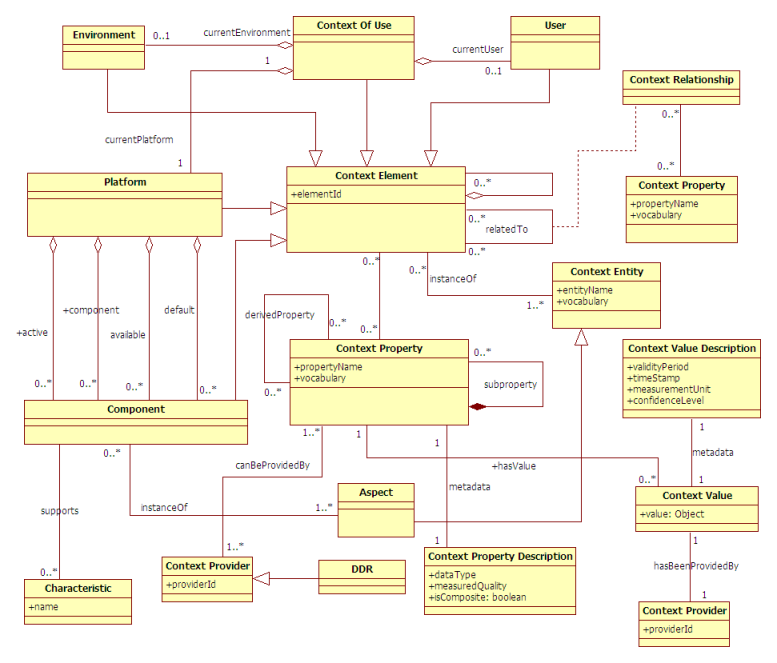
many aspects, it is not directly operational. Hence, we hereby 
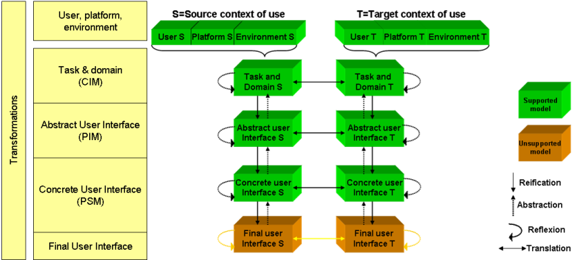
define the Context of Use of an interactive system as a dynamic, structured information space that includes the following entities:
Thus, a context of use is a triple composed by (U, P, E)
The User represents the human being (or a human stereotype) who is interacting with the system. The characteristics modelled or relevant can be very dependant on the application domain. Specific examples are age, level of experience, the permissions, preferences, tastes, abilities and disabilities, short term interests, long term interests, etc. In particular, perceptual, cognitive and action disabilities may be expressed in order to choose the best modalities for the rendering and manipulation of the interactive system.
The Platform is modeled in terms of resources, which in turn, determine the way information is computed, transmitted, rendered, and manipulated by users. Examples of resources include memory size, network bandwidth, and input and output interaction devices. [CCB02] distinguishes between elementary platforms (e.g. laptop, PDA, mobile phone), which are built from core resources (e.g. memory, display, processor) and extension resources (e.g. external displays, sensors, mice), and clusters, which are built from elementary platforms. Resources motivate the choice for a set of input and output modalities and, for each modality, the amount of information 
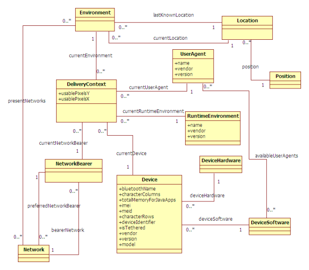
made available. W3C's Delivery Context Ontology [DCONTOLOGY] is intended to define a concrete Platform Model.
The Environment denotes the set of objects, persons
and events that are peripheral to the current activity but that may
have an impact on the system and/or users behavior, either now or
in the future
(Coutaz and Rey, 2002). According to our
definition, an environment may encompass the entire world. In
practice, the boundary is set up by domain analysts whose role is
to elicit the entities that are relevant to the case at hand.
Specific examples are: user's location, ambient sound, lighting or
weather conditions, present networks, nearby objects, user's social
networks, level of stress ...
The relationship between a UI and its contexts of use leads to the following definitions:
The CAMELEON Reference Framework, structures the development life cycle into four levels of abstraction, from the task specification to the running interface (see Figure 1):
These levels are structured with a relationship of reification going from an abstract level to a concrete one and a relationship of abstraction going from a concrete level to an abstract one. There can be also a relationship of translation between models at the same level of abstraction, but conceived for different contexts of use. These relationships are depicted on Figure 1.
Figure 1 - Relationships between components in the CAMELEON Reference Framework
After having identified relevant abstractions for models, the next issue is specifying them through a suitable language that enable integration within development environments, so as to facilitate the work of designers and developers. For this purpose, the notion of User Interface Description Language (UIDL) has emerged in order to express any aforementioned model.
A UIDL [GGC09] is a formal language used in HCI in order to describe a particular UI independently of any implementation technology. As such, the UI might involve different interaction modalities (e.g., graphical, vocal, tactile, haptic, multimodal), interaction techniques (e.g., drag and drop) or interaction styles (e.g., direct manipulation, form fillings, virtual reality). A common fundamental assumption of most UIDLs is that UIs are modelled as algebraic or model-theoretic structures that include a collection of sets of interaction objects together with behaviours over those sets. A UIDL can be used during:
The design process for a UIDL encompasses the definition of the following artefacts:
UIDL is
a more general term than "User Interface Markup Language"
(UIML) which is
often defined as [UIML-Def]: a
markup language that renders and describes graphical user
interfaces and controls. Many of these markup languages are
dialects of XML and are dependent upon a pre-existing scripting
language engine, usually a JavaScript engine, for rendering of
controls and extra scriptability.
Thus, as opposed to a
UIML, a UIDL is not
necessarily a markup language (albeit most UIDLs are) and does
not necessarily describe a graphical user interface (albeit most
UIDLs
abstract only graphical user interfaces).
[GGC09] includes a table comparing major UIDLs today. Most UIDLs are limited in scope and/or usage, have been stopped or are the property of some companies that do not allow their usage without paying any royalty. It can also be noticed that these UIDLs are very much heterogeneous in terms of coverage, aims, and goals, software support, etc. Hence, many UIDLs have been introduced so far, but still there is a need for a unified, standard UIDL that will encompass the fruitful experiences of the most recent of them.
The variety of the approaches adopted in organizations and the rigidity of existing solutions provide ample motivations for a UI development paradigm that is flexible enough to accommodate multiple development paths and design situations while staying precise enough to manipulate the information and knowledge required for UI development. To alleviate these problems, a development paradigm of multipath UI development is introduced by [LV09]. Such a development paradigm is characterized by both a transformational approach and multiple development paths formed by different development steps. Thus, different development steps can be combined together to form alternate development paths that are compatible with the organization's tools, contraints, conventions and contexts of use.
[LV09] describes different kinds of transformation steps:
Figure 2 - Forward and Reverse Engineering Development Paths
Transformation types have been introduced in the previous section. These transformation types are instantiated into development steps. These development steps may be composed to form development paths. Several types of development paths are identified by [LV09]:
The CAMELEON Reference Framework promotes a four-step forward engineering development path starting with domain concepts and task modelling. Although research in HCI has promoted the importance of task modelling, practicioners often skip this stage, and directly produce CUIs using protyping tools such as Flash because of the lack of tools allowing rapid prototyping from task models. This practice corresponds to the last two steps of the reification process recommended in the reference framework. Nonetheless, the framework can be instantiated with the number of reification steps that fits designers culture. In other words, designers can choose the entry point in the reification process that best fits their practice. If necessary, the missing abstractions higher in the reification process can be retrieved through reverse engineering
This section is intended to provide a better understanding of the different layers of abstraction introduced by the CAMELEON Reference Framework.
The first example illustrates how a simple web search interface can be modelled at different abstraction levels. At the task level the activities to be performed by the user to reach his goal are modelled. Then, the AUI level serves to model the interactors and containers which can support the user's tasks. It can be observed that such interactors are platform and modality independent. At the CUI level graphical concrete interactors and containers (window, textInput, button) have been introduced. Finally, CUI interactors are realized by means of HTML markup.
Figure 3 - An instantation of the CAMELEON Reference Framework
A more complex example is a UI intended for "Making a Hotel Reservation". From a task modelling point of view, it is a task that can be decomposed into selecting arrival and departure dates and other subtasks.
At the abstract user interface level we need to identify the interaction objects needed to support such tasks. For example, for easily specifying arrival and departure days we need selection interaction objects.
When we move on to the concrete user interface, we need to consider the specific interaction objects supported. So, in a desktop interface, selection can be supported by a graphical list object. This choice is more effective than others because the list supports a single selection from a potentially long list of elements.
The final user interface is the result of these choices and others involving attributes such as the type and size of the font, the colours, and decoration images that, for example, can show the list in the form of a calendar.
Many transformations are possible among these four levels for each interaction platform considered: from higher level descriptions to more concrete ones or viceversa or between the same level of abstraction but for different type of platforms or even any combination of them. Consequently, a wide variety of situations can be addressed. More generally, the possibility of linking aspects related to user interface elements to more semantic aspects opens up the possibility of intelligent tools that can help in the design, evaluation and run-time execution.
Figure 4 depicts graphically the "Context of Use" Model proposed by the NEXOF-RA Project [NEXOF-RA]. Such a Model captures the Context of Use in which a user is interacting with a particular computing platform in a given physical environment in order to achieve an interactive task.
Context of Use is the main entity which has been modelled as a an aggregation of User, Platform and Environment. They are all Context Elements. A Context Element is an instance of Context Entity. A Context Property represents a characteristic of a Context Element or information about its state. A Context Property might be associated to zero or more instances of Context Value. Examples of Context Property instances are: 'position', 'age' or 'cpuSpeed'. There can be Context Property instances composed by other sub-properties. For example, the 'position' property is typically composed by: 'latitude', 'longitude' and 'altitude'. Both a Context Property and a Context Value can be associated to different metadata represented by the Context Property Description and Context Value Description classes respectively. A Context Property can be obtained from different Context Providers. A Device Description Repository (DDR) [DDR-REQUIREMENTS] [DD-LANDSCAPE] is a Context Provider of information about the "a priori known" characteristics of Platform Components, particularly devices or web browsers.
The model below also describes a simple, abstract conceptual model for the Platform. A Platform can be represented as an aggregation of different Aspect [DDR-SIMPLE-API] instances (device, web browser, network, camera, ...), which are called Components. To this aim we have splitted this relationship into three different aggregations: active, default and available. active indicates that a Component is "running". For example, if a camera is "on" such a Component is said to be "active". default conveys what is the referred Aspect instance when there is no an explicit mention of a specific one. Finally, available represents what are the "ready to run" Components. For example, when a device has more than one web browser installed, the "available web browsers" property value will be a list containing a reference to the web browsers that could (potentially) be put into running.
Figure 4 - Context of Use Model (NEXOF-RA Project)
The Delivery Context Ontology (DCO) [DCONTOLOGY] is a W3C specification (work in progress) which provides a formal model of the characteristics of the environment in which devices interact with the Web or other services. The Delivery Context, as defined by [DI-GLOSS], includes the characteristics of the Device, the software used to access the service and the Network providing the connection among others. DCO is intended to be used as a concrete, standard Platform Model, even though due to convenience reasons it also models some Environment entities.
Figure 5 gives an overview of the main entities modelled by DCO. The root entity is the DeliveryContext class which is linked to the currentDevice, currentUserAgent, currentNetworkBearer and currentRuntimeEnvironment. The former are in fact active Components from the point of view of the Context of Use Model presented on the previous section. The Device class has been modelled as an aggregation of DeviceSoftware and DeviceHardware. In addition DCO also models some elements of the Environment such as the Location or the Networks present.
Figure 5 - Delivery Context Ontology : Main Entities
GUMO and UserML are two formalisms proposed by [HCK06] in order to deal with the problem of representing generic user models. The SITUATIONALSTATEMENTS and the exchange language UserML work on the syntactical level, while the general user model ontology GUMO has been developed (using OWL) on the semantical level. SITUATIONALSTATEMENTS represent partial descriptions of situations like user model entries, context information or low-level sensor data. SITUATIONALSTATEMENTS follow a layered approach of meta level information arranged in five boxes: mainpart , situation, explanation, privacy and administration. These boxes have an organizing and structuring functionality. An example of a SITUATIONALSTATEMENT represented in the UserML language can be seen below
<statement>
<mainpart>
<subject>Peter</subject>
<auxiliary>hasProperty</auxiliary>
<predicate>walkingSpeed</predicate>
<range>slow-medium-fast</range>
<object>fast</object>
</mainpart>
<situation>
<start>2010-04-09T19:20</start>
<end>?</end>
<durability>few minutes</durability>
<location>airport.dutyfree</location>
<position>X,Y,Z</position>
</situation>
<explanation>
<source>sensor.repository</source>
<creator>sensor.PW</creator>
<method>Bayes</method>
<evidence>LowLevelData</evidence>
<confidence>0.8</confidence>
</explanation>
<privacy>
<key>?</key>
<owner>Peter</owner>
<access>friends-only</access>
<purpose>research</purpose>
<retention>1 week</retention>
</privacy>
</statement>
Figure 6 - UserML Excerpt representing a SITUATIONALSTATEMENT
The main conceptual idea in the approach of SITUATIONALSTATEMENTS that influences the construction of the GUMO ontology is the division of descriptions of the user model dimensions into three parts: auxiliary, predicate and range as shown in the example above. As a matter of fact, the range attribute offers a new degree of freedom to the ontology definition: it decouples the definition for the predicate from possible range scales.
subject
{UserModelDimension}
object
subject
{auxiliary,predicate,range
} object
For example if one wants to say something about the user’s interest in football, one could divide this so-called user model dimension into the auxiliary part “has interest”, the predicate part “Football” and the range part “low-medium-high” as shown in the figure below. Likewise, If a system wants to express something like the user’s knowledge about Beethoven’s Symphonies, one could divide this into the triple “has knowledge”, “Beethoven’s Symphonies” and “poor-average-good-excellent”
Peter
{hasInterest,Football,
low-medium-high
} low
Peter
{hasKnowledge,Beethoven's
Symphonies
,poor-average-good-excellent
}
good
The implication for the general user model ontology GUMO of these examples above is the clear separation between user model auxiliaries, predicate classes and special ranges. What leads to a tricky problem is that actually everything can be a predicate if the auxiliary is “interest” or “knowledge”.
Information in the situation box is responsible for the temporal and spatial embedding of the whole statement in the real physical world. With this open approach one can handle the issue of the history in user modeling and context-awareness. Particularly the attribute durability carries the qualitative time span of how long the statement is expected to be valid (minutes, hours, days, years). In most cases when user model dimensions or context dimensions are measured, one has a rough idea about the expected durability, for instance, emotional states change normally within hours, however personality traits will not change within months.
The GUMO
Ontology defines both User Model Dimensions (e.g.
hasInterest
, hasKnowledge
,
hasProperty
, hasBelieve
,
hasPreference
) and User Model Auxiliaries (e.g.
Ability And Proficiency
, Personality
,
Emotional State
, Physiological State
,
Mental State
). However, as stated above, it turned
out that actually any concept in the whole world can be needed to
express user model data. To overcome such an issue the GUMO authors propose
to join in any other OWL ontology, Linked Data, or to use the
UBISWORLD Ontology. UBISWORLD can be used to represent some parts
of the real world like an office, a shop, a museum or an airport.
It represents persons, objects, locations as well as times, events
and their properties and features.
CTT is a notation for task model specifications which has been developed to overcome limitations of notations previously used to design interactive applications. Its main purpose is to be an easy-to-use notation that can support the design of applications of any degree of complexity.
The main features of CTT are:
A set of tools to develop task models in ConcurTaskTrees, to analyse their content and to generate corresponding UIs are being developed and are available at [CTTE].
The figure below shows a CTT task model which describes an ATM
UI. It has been modelled as two
different abstract tasks (depicted as a cloud):
EnableAccess
and Access
. There is an
enabling temporal relationship (>>
)
between them, which indicates that the Access
task can
only be performed after the successful completion of the
EnableAccess
task. If we have a look at the
EnableAccess
task it can be seen that it have been
splitted into: two interaction tasks (InsertCard
,
EnterPassword
) and an application (system-performed)
task (RequirePassword
). Likewise, the
Access
task has been decomposed into:
WithdrawCash
, DepositCash
and
GetInformation
. These tasks are related by means of
the choice ([]
) operator which indicates that
different tasks can be chosen, but once a task is chosen the other
will not be available until the former is finished. It can be
observed, particularly, the DecideAmount
task which it
is a user task, representing a cognitive activity. The
[]>>
symbol indicates an enabling with
information passing relationship, which means that there also
exists an information flow between the concerned tasks.
Figure 7 - CTT Task Model for the User Interface offered by an ATM
ANSI/CEA-2018 [Rich09] defines an XML-based language for task
model descriptions. The standard was published by CEA in Nov. 2007
[CEA2007], and by ANSI in March 2008. In this
standard a task model is defined as a formal description of the
activities involved in completing a task, including both activities
carried out by humans and those performed by machines
. The
standard defines the semantics and an XML notation for task models
relevant to consumer electronics devices, but nothing prevents
anybody from using it in a broader domain.
The figure below shows an XML excerpt of an ANSI/CEA-2018 task model for playing music on an entertainment system consisting of a media server and a media player [MBUI-CEA2018]. It can be observed that the main task is decomposed into different subtasks (steps). Steps are sequential by default, in the order as defined in the XML structure. Tasks have input and output slots, representing the data to be communicated with other tasks. Restrictions over such data are expressed by means of Preconditions and Postconditions. Bindings specify the data flow between the input and output slots of a task and its subtasks, and those between the subtasks.
<taskModel>
<task id='playMusic'>
<subtasks id='playMusicSteps' ordered='false'>
<step name='select' task='selectMusic' />
<step name='configure' task='configureRenderer' />
<step name='connect' task='connect' requires='select configure' />
<step name='play' task='play' requires='connect' />
<binding slot='$connect.preferredConnectionProtocol' value=''*'' />
</subtasks>
</task>
<task id='connect'>
<input name='preferredConnectionProtocol' type='string' />
<output name='newConnectionId' type='string' />
<output name='error' type='ErrorDescription' />
</task>
</taskModel>
Figure 8 - XML excerpt of an ANSI/CEA-2018 task model for playing music
MARIA [PSS09] Model-based lAnguage foR Interactive Applications, is a universal, declarative, multiple abstraction level language for service-oriented applications in ubiquitous environments. It provides a flexible dialogue and navigation model, a flexible data model, which allows the association of various types of data to the various interactors, and support for more recent techniques able to change the content of UIs asynchronously respect to the user interaction.
Figure 9 shows the main elements of the abstract user interface metamodel (some details have been omitted for clarity). As can be seen, an interface is composed of one data model and one or more presentations. Each presentation is composed of name, a number of possible connections, elementary interactors, and interactor compositions. The presentation is also associated with a dialog model which provides information about the events that can be triggered at a given time. The dynamic behavior of the events, and the associated handlers, is specified using the CTT temporal operators (for example, concurrency, or mutually exclusive choices, or sequentiality, etc.).
Figure 9 - MARIA AUI Meta-Model
When an event occurs, it produces a set of effects (such as performing operations, calling services, etc.) and can change the set of currently enabled events (for example, an event occurring on an interactor can affect the behavior of another interactor, by disabling the availability of an event associated to another interactor). The dialog model can also be used to describe parallel interaction between user and interface. A connection indicates what the next active presentation will be when a given interaction takes place. It can be either an elementary connection, a complex connection (when Boolean operators compose several connections), or a conditional connection (when specific conditions are associated with it). There are two types of interactor compositions: grouping or relation. The latter has at least two elements (interactor or interactor compositions) that are related to each other.
In MARIA an interactor can be either an interaction object or an "only output" object. The first one can be one of the following types: selection, edit, control, interactive description, depending on the type of activity the user is supposed to carry out through such objects. The control object is refined into two different interactors depending on the type of activity supported (navigator: navigate between different presentations; activator: trigger the activation of a functionality). An only output interactor can be object, description, feedback, alarm, text, depending on the supposed information that the application provides to the user through this interactor.
It is worth pointing out that further refinement of each of these interactors can be done only by specifying some platform-dependent characteristics, therefore it is specified at the concrete level.
UsiXML [LVMBL04] [UsiXML-Proj] is an XML-compliant markup language, which aims to describe the UI for multiple contexts of use. UsiXML adheres to MBUI by having meta-models describing different aspects of the UI. At the time of writing a new version of UsiXML is under development thanks to the support of an Eureka ITEA2 project [UsiXML-Proj].
The figure below depicts the current version of the UsiXML Meta-Model for AUI description (work in progress). The class AUIobject is at the top of the hierarchy representing the elements that populate an AUI Model. AUIInteractor and AUIContainer are subsumed by AUIObject. The latter defines a group of tasks that have to be presented together and may contain both AuiInteractors or other AuiContainers. An association class AuiRelationship allows to define the kind of relationship (Ordering, Hierarchy, Grouping, or Repetition) between an object and its container. AUIInteractionUnit is an aggregation of AUIObject and Behaviour specified by means of Listener, Event and Action. AuiInteractor has been splitted into DataInteractor (for UI data input/output) or TriggerInteractor (for UI command). Selection,Input and Output are data interactors. Concerning trigger interactors, Command is intended to launch any kind of action within the UI whilst Navigator allows to change the interaction unit.
Figure 10 - Abstract User Interface Meta-Model in UsiXML
Figure 11 is the graphical representation of the UsiXML Meta-model for the Concrete UI (work in progress). The root entity is CUIObject which has been subclassed in CUIInteractor and CUIContainer. The relationship between Interactors and Containers is captured by the 'contains' relationship and the CUIRelationship association class. It is important to note that the meta-model includes specializations for the different modalities (graphical, tactile, vocal), as a CUI Model is modality-dependent. The Style class is intended to capture all the presentational attributes for a CUI Object. This design pattern decouples the model from 'presentational vocabularies'.
Figure 11 - UsiXML CUI Meta-Model
Figure 12 depicts the hierarchy of GraphicalInteractor modelled by UsiXML. As it can be observed, the typical graphical interactors found in conventional toolkits are included.
Figure 12 - UsiXML CUI Graphical Interactors
The UsiXML meta-models presented above are still under development, thus many issues are open. For example, layout representation, bindings between the Domain Model and the AUI / CUI, model modularization and extension, etc.
MyMobileWeb [MYMW] is an open source, standards-based software framework that simplifies the rapid development of mobile web applications and portals. MyMobileWeb encompasses a set of technologies which enable the automatic adaptation to the target Delivery Context [DI-GLOSS], thus offering a harmonized user experience. Concerning Model-Based approaches, the technologies offered by MyMobileWeb are:
IDEAL2 is an XML-based language aimed to simplify the creation of web applications and contents that adapt to their delivery context. IDEAL2 is easy to be learned by web developers, modular and standards-compliant (it makes use of XForms [XFORMS11] and DISelect [CSELECTION]). By using IDEAL2 authors can concentrate on the application functionality without worrying about markup implementation languages or scripting capabilities. Interaction units (presentations) are described using XML elements that correspond to containers (section, div) and interactors (select, select1, input, output, menu, ...). Designers can force specific mappings between the AUI layer and the graphical, mobile CUI layer by means of attributes expressed using the CSS2 [CSS2] syntax. The decision on how an interactor will be finally rendered will depend on the device and web browser identified at runtime. For example, a select1 element can be rendered as a drop down list, a set of radio buttons or as a nice navigation list with hyperlinks. Specific examples on the usage of IDEAL2 can be found on [MyMw-Tut].
SCXML is a W3C standard for specifiying state machines based on Harel State Tables. SCXML provides XML elements to define states, transitions between states and actions to be performed when certain conditions are met. According to the MyMobileWeb conventions, a state typically denotes that the user is interacting with a presentation. There are, at least, as many states as presentations. User interaction events (activate,submit, etc.) trigger transitions. Actions correspond to the executable content (application logic execution, navigation) that has to be launched when a transition is triggered or when a state is entered. Concrete examples on the usage of SCXML within MyMobileWeb are available at [MyMw-Tut].
This section presents a set of compelling use cases on which model-based design of UIs will be particularly suitable.
Digital home refers to a residence with devices that are connected through a computer network. A digital home has a network of consumer electronics, mobile, and PC devices that cooperate transparently and simplify usability at home. All computing devices and home appliances conform to a set of interoperable standards so that everything can be controlled by means of an interactive system. Different electronic services can be offered by a digital home system, including but not limited to:
These functionalities should be made available through context-sensitive front-ends. In fact, such front-ends have to be capable of adapting to different computing platforms (touch points, web, mobile, TV, Home PDA, DECT handset, voice portal …), users (children, teenagers, adults, the elderly, disabled people, …) and environments or situations (at home, away, at night, while music is playing, …). The final aim is to provide a seamless and unified user experience which it is critical in the digital home domain. At this respect different automatic UI adaptations can be possible:
We believe that new standards are necessary to cater the needs imposed by the scenario described above. Dynamic variations in the computing platform, user and environment dimensions of the context of use will be automatically accommodated, thus supporting users in a more effective, personalized and consistent way. Furthermore, the engineering costs of developing context-sensitive front-ends for the digital home will be cut off, and lastly, the time to market will be improved.
In order to ensure a just-in-time deployment of relevant components to the respective assembly stations, many companies define a proceeding consignment step. Here workers run off storage racks in a warehouse intending to collocate the necessary parts. The workers of the succeeding assembly step strongly rely on a correct consignment. An uncompleted consignment will lead to a downtime of the production line, which is translated into losses for the company. In a similar manner, inaccurate pickings will affect a company's success and increase workers' frustration. Therefore, the picking process makes high quality and time demands on the workers. Especially the fact that warehouses employ unskilled workers to relieve the work load during peak times makes consignment a critical task and bottleneck in the overall process. The problem is that workers are often unfamiliar with warehouse settings. Additionally, they neither know the products nor have the necessary skills to carry out the job on their own.
Imagine John who is working as commissioner in an automobile company. For large orders, John collects the relevant components utilizing a cart. The necessary components and their location are shown in lists on a display mounted on the cart. Since John can orient himself only in subsections of the warehouse, he can additionally make use of a head mounted display (HMD). Using the HMD, relevant components are no longer displayed as lists. John gets a visual representation of the number and location of the objects ( (storage rack and box number) he is looking for. Furthermore, John receives direct feedback on the HMD in the case of wrong or missing parts. For smaller orders or single parts, John often moves more efficiently without the large storage cart. In that case, John can read details about relevant components as well as their location on a GUI running on his cell phone.
The described use case motivates how proactive applications can provide unobtrusive and adequate help (e.g. missing parts, location of necessary parts, etc.) when the user needs help. Thereby, the service time can be reduced while increasing the quality of service. Note that human computer interaction can happen on manifold output devices strongly depending on the context of use -e.g., user’s identity and preferences, task size, or display resolution. In this case both user input and output have to be considered when designing a multi-channel system. Whereas a use of several channels for processing the same information provides an increased bandwidth of information transfer, the development of multi-channel applications is still complex and expensive due to lacking tools. A simplification of the development of adaptive multi-channel applications by providing an integrated, model-based development and runtime environment seems to be crucial and a key factor.
Migratory user interfaces are interactive applications that can transfer among different devices while preserving the state and therefore giving the sense of a non-interrupted activity. The basic idea is that devices that can be involved in the migration process should be able to run a migration client, which is used to allow the migration infrastructure to find such devices and know their features. Such client is also able to send the trigger event to the migration server, when it is activated by the user. At that point the state of the source interface will be transmitted to the server in order to be adapted and associated to the new UI automatically generated for the target device.
Figure 13 shows how the abstraction layers are exploited to support migratory UIs, by showing the various activities that are done by the Migration Server. This solution has been developed in the EU OPEN Project [OPEN]. First of all the migration approach assumes that various UI models at different abstraction levels are associated to the various devices involved in a migration: such UI models are stored/manipulated centrally, in the Migration Server.
The current architecture assumes that a desktop Web version of the application front-end exists and it is available in the corresponding Application Server: this seems a reasonable assumption given the wide availability of this type of applications. Then, from such final UI version for the desktop platform, the Migration Server automatically generates a logical, concrete UI description for the desktop platform through a reverse-engineering process. After having obtained such a concrete UI description for the desktop platform, the Migration server performs a semantic redesign of such CUI [PSS08] for creating a new, concrete, logical description of the UI, adapted to the target device.
The purpose of the semantic redesign is to preserve the semantics of the user interactions that should be available for the user but to adapt the structure of the UI to the resources available in the target device. It may happen that some task is not supported by the target device (e.g. a long video cannot be rendered with a limited mobile phone).
For all the tasks that can be supported the semantic redesign identifies concrete techniques that preserve the semantics of the interaction but supports it with techniques most suitable for the new device (for example in mobile devices it will replace interactors with others that provide the same type of input but occupying less screen space). In a similar way also page splitting is supported: when there are pages too heavy for the target device they are split taking into account their logical structure so that elements logically connected remain in the same page. Thus, the groupings and relations are identified and some of them are allocated to newly created presentations so that the corresponding page can be sustainable by the target devices.
Figure 13 - The relationships among abstraction layers supporting migration
This section describes a complete example that illustrates how to apply model-based approaches to the design of a multi-target UI for controlling a Digital Home. Such a system allows to control domestic appliances, room conditions or entertainment devices, like DVD players or video consoles. Our design process is following a forward engineering development path in accordance with the Cameleon Reference Framework. Thus, we are first creating a Task Model, then a AUI Model and finally a CUI Model (in this particular case for the graphical mobile platform). The following sections depicts and describes briefly such models.
An excerpt of the CTT Task Model for the proposed case of study is shown below. In addition it is shown a brief sketch of a hypothetical XML-based representation of such a model. It can be observed that in a task model the two most important aspects are the hierarchical decomposition and the temporal relationships. In addition at this abstraction level certain contextual conditions can be expressed, for instance, that a certain task (Entertainment) is only going to be available while the user is at home. One important detail not covered by the excerpt presented are the domain objects manipulated by the tasks.
Figure 14 - Digital Home CTT Task Model (overview)
<taskModel>
<task id='root' name='Digital Home' type='abstract'>
<relations>
<enabling left='login' right='access' />
<deactivation left='access' right='close' />
</relations>
</task>
<task id='access' name='Control System' type='abstract' parent='root'>
<relations>
<choice>
<task id='home' />
<task id='entmt'>
<contextCondition situation='atHome' />
</task>
<task id='presence' />
</choice>
</relations>
</task>
<task id='home' name='Control Home' type='abstract' parent='access'>
<relations>
<choice>
<task id='crooms' />
<task id='domesticappls' />
</choice>
</relations>
</task>
<task id='croom' type='abstract' parent='home' name='Control Rooms'>
<relations>
<enablingInfo left='selroom' right='control' />
</relations>
</task>
</taskModel>
Figure 15 - (Sketched) XML Representation of a CTT task model for a digital home
The figure below describes (partially) a (UsiXML) AUI Model corresponding to the Task Model presented on the previous section. For reading convenience reasons, the AUI Model has been represented using a hypothetical, XML-based, concrete syntax. The AUI model is focusing on: (a) the relationship between interactors and containers, (b) the UI behaviour (action elements) and (c) the bindings with the domain model (ref attributes). More specific implementation details such as layout, particular interactors or themes are specified at the CUI level.
<auiModel>
<auiInteractionUnit id='home' title='Digital Home'>
<auiContainer relation='group'>
<navigation id='nchome' target='control'>
<label lang='eng'>Control Home</label>
</navigation>
<navigation id='nentert' target='entertainment'>
<label lang='eng'>Entertainment</label>
<contextCondition situation='atHome' />
</navigation>
<navigation id='npresence' target='presence'>
<label lang='eng'>Presence</label>
</navigation>
</auiContainer>
</auiInteractionUnit>
<auiInteractionUnit id='control' title='Control Rooms'>
<behaviour>
<action target='c1' event='commandTrigger'>
<modelUpdate />
<executeFunction name='thermostat.setTemperature' />
</action>
<action target='temp' event='dataSelection'>
<modelUpdate />
<objectActivate target='tempContainer' />
</action>
<action target='img' event='dataSelection'>
<modelUpdate />
<navigate target='roomImage' />
</action>
<action target='light' event='dataSelection'>
<modelUpdate />
<navigate target='light' />
</action>
</behaviour>
<auiContainer relation='group'>
<input id='room' ref='room.number'>
<label>Enter Room</label>
</input>
<selection id='sel' ref='option'>
<item id='temp'>
<label>Control Temperature</label>
</item>
<item id='img'>
<label>Show Room Image</label>
</item>
<item id='light'>
<label>Control Light</label>
</item>
</selection>
<auiContainer id='tempContainer' relation='group' active='false'>
<output ref='room.number'>
<label>Temperature Settings for Room:</label>
</output>
<input id='itemp' ref='room.desiredTemperature' type='number'>
<label>Enter Desired Temperature</label>
</input>
<command id='c1'>
<label>Accept</label>
</command>
</auiContainer>
</auiContainer>
</auiInteractionUnit>
</auiModel>
Figure 16 - (Sketched) XML Representation of the AUI Model
For the CUI Model we have chosen the mobile graphical platform as the target. Since there can be multiple variations within this platform, we have decided to express our CUI Model using IDEAL2. The figure below shows the IDEAL2 representation of one of the interaction units captured by our AUI Model. For simplicity reasons we are not providing the associated CSS stylesheet with the corresponding visual properties (background colors, font sizes, layout, etc.). It is important to note that the navigator elements in the AUI Model have been transformed into a menu component and a set of hyperlinks. The "Entertainment" option has disappeared at this level, as in a mobile context we have considered that it makes no sense. A header and a footer have been added in order to make the application more attractive for the end user. It is noteworthy that at this level of abstraction, we have not specificed any behaviour as it is meant to be 'inherited' from the AUI Model. Once this CUI Model is available, it would be deployed to a MyMobileWeb environment and finally rendered at runtime (using HTML) in accordance with the target Delivery Context.
<cuiModel>
<resources>
<link rel='stylesheet' href='digitalHome.css' />
</resources>
<presentation id='initial'>
<body>
<header id='header'>
<img src='mydigitalHome' alt='Nice Header' />
</header>
<section id='main'>
<div id='p1' class='dhome'>
<menu id='myMenu' class='mymenus'>
<a href='#chome'>Control Home</a>
<a href='#presence'>Presence</a>
</menu>
</div>
</section>
<footer id='footer'>
<p>Application provided by ...</p>
</footer>
</body>
</presentation>
</cuiModel>
Figure 17 - (Sketched) XML Representation of the CUI Model using IDEAL2
The case of study covered by this section has given a taste of how Model-Based Design of UIs works by progressive refinement: from the interaction semantics captured by the task model to the lower-level implementation details described by the CUI. However, our example has not provided a description of how transformations and mappings between the different abstraction layers would be specified. In other words, there should be mechanisms to easily move from one layer of abstraction to the next without effort duplication. Furthermore, ideally, tools should provide default transformations that allow, for instance, to create a default AUI from a Task Model or a default CUI from an AUI, among others.
In general it can be said that Model-Based Engineering provides the following benefits:
More specifically Model-Based UIs present the following advantages:
In our opinion, after more than fifteen years of research, MBUI approaches are in a very good position to be deployed in a mass scale. In fact, the current technological context is posing the challenge of creating, in time to market, compelling applications intended to multiple Contexts of Use (specially the mobile), while at the same time minimizing costs. We strongly believe that MBUI approaches can contribute to meet these requirements. Nonetheless, we have identified the following challenges that have to be faced in the near future in order to be successful:
We believe that time has come for standardization in the area of Model-Based User Interfaces. Furthermore, we believe that standards can help to transfer to the industry results of the research conducted during the last fifteen years. As a matter of fact, from the state of the art presented by this work, it can be concluded that at least there is a high level of consensus in a potential baseline for MBUI (abstraction layers and model semantics).
As a first step in the standardization process we suggest to start with the definition of the baseline meta-models and semantics for the different abstraction layers (Task & Concepts, AUI, CUI). Furthermore, we believe that it would be rather challenging (and likely to fail) to try to standardize UIDL abstractions (meta-models) and semantics together with a concrete syntax. This is due to the fact that our past experience indicates that it is quite more difficult to get an agreement on a common syntax than on common meta-models and semantics. Thus, multiple concrete syntaxes (but translatable between) might co-exist for the same Meta-Models (semantics). This approach can be summarized as follows: One (standard) Model, Many Syntaxes. For instance, OWL2 [OWL2-PRIMER] has embraced the same principle.
Another advantage of standardization at the semantic and meta-model level is that it will enable an incremental (and interoperable) adoption by software vendors that currently own XML-based languages for describing UIs. Thus, supporting the standard UIDLs could be as easy as creating syntax translators or generators from / to the standard Models. For instance, if we consider XForms as an specific syntax for the AUI Model, it should be feasible to convert an XForms specification into an AUI model and viceversa.
Once Models are widely adopted a future action might consider the standardization of a common abstract or concrete syntax if from the experience it is concluded that everybody are using slightly similar syntaxes and, as a consequence, agreement is feasible.
Taking into account the previous facts,a first W3C WG on MBUI might be chartered on the following work items:
These are initial suggestions indeed. Before chartering the group it will be needed to investigate the amount of resources available to write the corresponding specifications. Nonetheless, we think that AUI and CUI should have priority over other layers.
During the last year and a half the MBUI-XG group has analyzed the state of the art and potential of Model-Based approaches in the development of multi-target UIs. As a collorary the MBUI-XG has organized a Workshop [MBUI-Wksp] aimed at listening to the community to contrast different views on the subject. In addition the Workshop will serve as a public consultation instrument before taking a final decision concerning the creation of a regular W3C Working Group on MBUI.
At the time of writing the academic community, a few telco companies and some niche SMEs (specialized in Model-Based technologies) are very interested in standardization. At this respect, we believe that, sooner or later, our proposed, non-intrusive standardization approach will serve to get other actors (such as big independent software vendors or device manufacturers) on board. This will be, hopefully, stimulated by the appearance of automatic translators and converters between proprietary UIDLs and the future W3C standards.
Lastly, it is important to take into account that the existence of interoperable implementations will be critical in order to progress the specifications towards the Recommendation stage. At the time of writing, we know at least two SMEs and one research center that would be willing to implement the future standards within their Model-Based tools and frameworks.
This work was partially supported by the following R&D projects:
Thomas Ziegert and his team at SAP AG who provided the "Warehouse Consignment" use case.