7 Coordinate Systems, Transformations and Units
7.1 Introduction
For all media, the SVG canvas
describes "the space where the SVG content is rendered." The
canvas is infinite for each dimension of the space, but
rendering occurs relative to a finite rectangular region of the
canvas. This finite rectangular region is called the SVG viewport. For visual media [
CSS2-VISUAL], the SVG viewport is the viewing area where
the user sees the SVG content.
The size of the SVG viewport (i.e., its width and height) is
determined by a negotiation process (see Establishing the size of the initial
viewport) between the SVG document fragment and its parent
(real or implicit). Once that negotiation process is completed,
the SVG user agent is provided the following information:
- a number (usually an integer) that represents the width
in "pixels" of the viewport
- a number (usually an integer) that represents the height
in "pixels" of the viewport
- (highly desirable but not required) a real number value
that indicates the size in real world units, such as
millimeters, of a "pixel" (i.e., a px unit as
defined in [
CSS2 lengths])
Using the above information, the SVG user agent determines
the viewport, an initial viewport coordinate system and an
initial user coordinate system
such that the two coordinates systems are identical. Both
coordinates systems are established such that the origin
matches the origin of the viewport (for the root viewport, the
viewport origin is at the top/left corner), and one unit in the
initial coordinate system equals one "pixel" in the viewport.
(See Initial
coordinate system.) The viewport coordinate system is also
called viewport space and the
user coordinate system is also called user space.
Lengths in SVG are specified as values in user space
(e.g. "15") and in a couple of special cases with an additional absolute
unit measure (e.g. "15mm"). See Units for details.
A new user space (i.e., a new current coordinate system) can
be established at any place within an SVG document fragment by
specifying transformations in the
form of transformation matrices
or simple transformation operations such as rotation, skewing,
scaling and translation. Establishing new user spaces via coordinate system
transformations are fundamental operations to 2D graphics
and represent the usual method of controlling the size,
position, rotation and skew of graphic objects.
New viewports also can be established. By establishing a new
viewport, you can provide a new reference rectangle for "fitting" a graphic
into a particular rectangular area. ("Fit" means that a given
graphic is transformed in such a way that its bounding box in
user space aligns exactly with the edges of a given
viewport.)
7.2 The initial viewport
The SVG user agent negotiates with its parent user agent to
determine the viewport into which the SVG user agent can render
the document. In some circumstances, SVG content will be
embedded (by reference or
inline) within a containing document. This containing
document might include attributes, properties and/or other
parameters (explicit or implicit) which specify or provide
hints about the dimensions of the viewport for the SVG content.
SVG content itself optionally can provide information about the
appropriate viewport region for the content via the width and height XML attributes on the 'svg' element. The
negotiation process uses any information provided by the
containing document and the SVG content itself to choose the
viewport location and size.
The width attribute on the
'svg' element
establishes the viewport's width, unless the following
conditions are met:
- the SVG content is a separately stored resource that is
embedded by reference (such as the 'object' element in [XHTML]), or the SVG
content is embedded inline within a containing document;
- and the referencing element or containing document is
styled using CSS [CSS2] or XSL [XSL];
- and there are CSS-compatible positioning properties [
CSS2-POSN] specified on the referencing element (e.g.,
the 'object' element) or on
the containing document's 'svg' element that are sufficient
to establish the width of the viewport.
Under these conditions, the positioning properties establish
the viewport's width.
Similarly, if there are positioning properties [
CSS2-POSN] specified on the referencing element that are
sufficient to establish the height of the viewport, then these
positioning properties establish the viewport's height;
otherwise, the height attribute
on the 'svg'
element establishes the viewport's height.
If the width or height attributes on the
'svg' element are in user units (i.e., no unit
identifier has been provided), then the value is assumed to be
equivalent to the same number of "px" units (see Units).
In the following example, an SVG graphic is embedded inline
within a parent XML document which is formatted using CSS
layout rules. The width="100px" and
height="200px" attributes
determine the size of the initial viewport:
<?xml version="1.0" standalone="yes"?>
<parent xmlns="http://some.url">
   <!-- SVG graphic -->
   <svg xmlns='http://www.w3.org/2000/svg'
      width="100px" height="200px" version="1.1">
      <path d="M100,100 Q200,400,300,100"/>
      <!-- rest of SVG graphic would go here -->
   </svg>
</parent>
7.3 The initial coordinate system
For the 'svg' element, the SVG user
agent determines an initial viewport
coordinate system and an initial user coordinate system such that the
two coordinates systems are identical. The origin of both
coordinate systems is at the origin of the viewport, and one
unit in the initial coordinate system equals one "pixel" (i.e.,
a px unit as defined in [ CSS2
lengths]) in the viewport. In most cases, such as
stand-alone SVG documents or SVG document fragments embedded
(by reference or
inline) within XML parent documents where the parent's
layout is determined by CSS [CSS2] or XSL [XSL], the initial viewport
coordinate system (and therefore the initial user coordinate
system) has its origin at the top/left of the viewport, with
the positive x-axis pointing towards the right, the positive
y-axis pointing down, and text rendered with an "upright"
orientation, which means glyphs are oriented such that Roman
characters and full-size ideographic characters for Asian
scripts have the top edge of the corresponding glyphs oriented
upwards and the right edge of the corresponding glyphs oriented
to the right.
If the SVG implementation is part of a user agent which
supports styling XML documents using CSS2-compatible
px units, then the SVG user agent should get its
initial value for the size of a px unit in real world
units to match the value used for other XML styling operations;
otherwise, if the user agent can determine the size of a
px unit from its environment, it should use that
value; otherwise, it should choose an appropriate size for one
px unit. In all cases, the size of a px must
be in conformance with the rules described in [ CSS2
lengths].
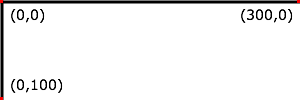
Example 07_02 below
shows that the initial coordinate system has the origin at the
top/left with the x-axis pointing to the right and the y-axis
pointing down. The initial user coordinate system has one user
unit equal to the parent (implicit or explicit) user agent's
"pixel".
<?xml version="1.0" standalone="no"?>
<svg width="300px" height="100px" version="1.2" baseProfile="tiny"
     xmlns="http://www.w3.org/2000/svg">
  <desc>Example InitialCoords - SVG's initial coordinate system</desc>
  <g fill="none" stroke="black" stroke-width="3" >
    <line x1="0" y1="1.5" x2="300" y2="1.5" />
    <line x1="1.5" y1="0" x2="1.5" y2="100" />
  </g>
  <g fill="red" stroke="none" >
    <rect x="0" y="0" width="3" height="3" />
    <rect x="297" y="0" width="3" height="3" />
    <rect x="0" y="97" width="3" height="3" />
  </g>
  <g font-size="14" font-family="Verdana" >
    <text x="10" y="20">(0,0)</text>
    <text x="240" y="20">(300,0)</text>
    <text x="10" y="90">(0,100)</text>
  </g>
</svg>
7.4 Coordinate system transformations
A new user space (i.e., a new current coordinate system) can
be established by specifying transformations in the form of a transform attribute on a container
element or graphics element or a viewBox attribute on the 'svg' element. The transform and viewBox attributes transform user
space coordinates and lengths on sibling attributes on the
given element (see effect
of the transform attribute on
sibling attributes and effect
of the viewBox attribute on
sibling attributes) and all of its descendants.
Transformations can be nested, in which case the effect of the
transformations are cumulative.
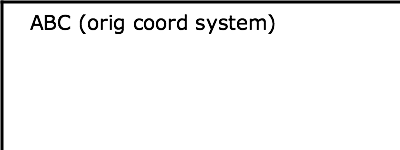
Example 07_03 below
shows a document without transformations. The text string is
specified in the initial coordinate
system.
<?xml version="1.0" standalone="no"?>
<svg width="400px" height="150px" version="1.2" baseProfile="tiny"
     xmlns="http://www.w3.org/2000/svg">
  <desc>Example OrigCoordSys - Simple transformations: original picture</desc>
  <g fill="none" stroke="black" stroke-width="3" >
    <!-- Draw the axes of the original coordinate system -->
    <line x1="0" y1="1.5" x2="400" y2="1.5" />
    <line x1="1.5" y1="0" x2="1.5" y2="150" />
  </g>
  <g>
    <text x="30" y="30" font-size="20" font-family="Verdana" >
      ABC (orig coord system)
    </text>
  </g>
</svg>
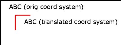
Example 07_04
establishes a new user coordinate system by specifying transform="translate(50,50)" on the
third 'g' element below. The
new user coordinate system has its origin at location (50,50)
in the original coordinate system. The result of this
transformation is that the coordinate (30,30) in the new user
coordinate system gets mapped to coordinate (80,80) in the
original coordinate system (i.e., the coordinates have been
translated by 50 units in X and 50 units in Y).
<?xml version="1.0" standalone="no"?>
<svg width="400px" height="150px" version="1.2" baseProfile="tiny"
     xmlns="http://www.w3.org/2000/svg">
  <desc>Example NewCoordSys - New user coordinate system</desc>
  <g fill="none" stroke="black" stroke-width="3" >
    <!-- Draw the axes of the original coordinate system -->
    <line x1="0" y1="1.5" x2="400" y2="1.5" />
    <line x1="1.5" y1="0" x2="1.5" y2="150" />
  </g>
  <g>
    <text x="30" y="30" font-size="20" font-family="Verdana" >
      ABC (orig coord system)
    </text>
  </g>
  <!-- Establish a new coordinate system, which is
       shifted (i.e., translated) from the initial coordinate
       system by 50 user units along each axis. -->
  <g transform="translate(50,50)">
    <g fill="none" stroke="red" stroke-width="3" >
      <!-- Draw lines of length 50 user units along
           the axes of the new coordinate system -->
      <line x1="0" y1="0" x2="50" y2="0" stroke="red" />
      <line x1="0" y1="0" x2="0" y2="50" />
    </g>
    <text x="30" y="30" font-size="20" font-family="Verdana" >
      ABC (translated coord system)
    </text>
  </g>
</svg>
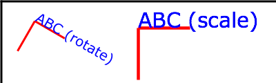
Example 07_05
illustrates simple rotate and
scale transformations. The example defines two
new coordinate systems:
- one which is the result of a translation by 50 units in X
and 30 units in Y, followed by a rotation of 30 degrees
- another which is the result of a translation by 200 units
in X and 40 units in Y, followed by a scale transformation of
1.5.
<?xml version="1.0" standalone="no"?>
<svg width="400px" height="120px" version="1.2" baseProfile="tiny"
     xmlns="http://www.w3.org/2000/svg">
  <desc>Example RotateScale - Rotate and scale transforms</desc>
  <g fill="none" stroke="black" stroke-width="3" >
    <!-- Draw the axes of the original coordinate system -->
    <line x1="0" y1="1.5" x2="400" y2="1.5" />
    <line x1="1.5" y1="0" x2="1.5" y2="120" />
  </g>
  <!-- Establish a new coordinate system whose origin is at (50,30)
       in the initial coord. system and which is rotated by 30 degrees. -->
  <g transform="translate(50,30)">
    <g transform="rotate(30)">
      <g fill="none" stroke="red" stroke-width="3" >
        <line x1="0" y1="0" x2="50" y2="0" />
        <line x1="0" y1="0" x2="0" y2="50" />
      </g>
      <text x="0" y="0" font-size="20" font-family="Verdana" fill="blue" >
        ABC (rotate)
      </text>
    </g>
  </g>
  <!-- Establish a new coordinate system whose origin is at (200,40)
       in the initial coord. system and which is scaled by 1.5. -->
  <g transform="translate(200,40)">
    <g transform="scale(1.5)">
      <g fill="none" stroke="red" stroke-width="3" >
        <line x1="0" y1="0" x2="50" y2="0" />
        <line x1="0" y1="0" x2="0" y2="50" />
      </g>
      <text x="0" y="0" font-size="20" font-family="Verdana" fill="blue" >
        ABC (scale)
      </text>
    </g>
  </g>
</svg>
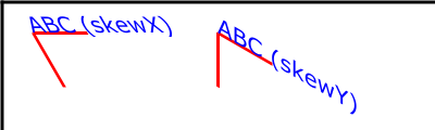
Example 07_06 defines two
coordinate systems which are skewed relative
to the origin coordinate system.
<?xml version="1.0" standalone="no"?>
<svg width="400px" height="120px" version="1.2" baseProfile="tiny"
     xmlns="http://www.w3.org/2000/svg">
  <desc>Example Skew - Show effects of skewX and skewY</desc>
  <g fill="none" stroke="black" stroke-width="3" >
    <!-- Draw the axes of the original coordinate system -->
    <line x1="0" y1="1.5" x2="400" y2="1.5" />
    <line x1="1.5" y1="0" x2="1.5" y2="120" />
  </g>
  <!-- Establish a new coordinate system whose origin is at (30,30)
       in the initial coord. system and which is skewed in X by 30 degrees. -->
  <g transform="translate(30,30)">
    <g transform="skewX(30)">
      <g fill="none" stroke="red" stroke-width="3" >
        <line x1="0" y1="0" x2="50" y2="0" />
        <line x1="0" y1="0" x2="0" y2="50" />
      </g>
      <text x="0" y="0" font-size="20" font-family="Verdana" fill="blue" >
        ABC (skewX)
      </text>
    </g>
  </g>
  <!-- Establish a new coordinate system whose origin is at (200,30)
       in the initial coord. system and which is skewed in Y by 30 degrees. -->
  <g transform="translate(200,30)">
    <g transform="skewY(30)">
      <g fill="none" stroke="red" stroke-width="3" >
        <line x1="0" y1="0" x2="50" y2="0" />
        <line x1="0" y1="0" x2="0" y2="50" />
      </g>
      <text x="0" y="0" font-size="20" font-family="Verdana" fill="blue" >
        ABC (skewY)
      </text>
    </g>
  </g>
</svg>
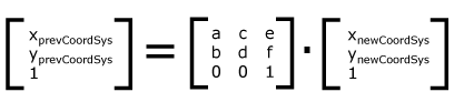
Mathematically, all transformations can be represented as
3x3 transformation matrices of
the following form:
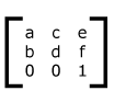
Since only six values are used in the above 3x3 matrix, a
transformation matrix is also expressed as a vector: [a
b c d e f].
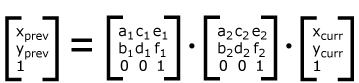
Transformations map coordinates and lengths from a new
coordinate system into a previous coordinate system:
Simple transformations are represented in matrix form as
follows:
-
Translation is equivalent to the matrix
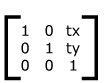
or [1 0 0 1 tx ty], where tx and
ty are the distances to translate coordinates in
X and Y, respectively.
- Scaling is
equivalent to the matrix
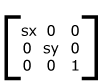
or [sx 0 0 sy 0 0]. One unit in the
X and Y directions in the new coordinate
system equals sx and sy units in the
previous coordinate system, respectively.
- Rotation
about the origin is equivalent to the matrix
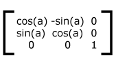
or [cos(a) sin(a) -sin(a) cos(a) 0 0],
which has the effect of rotating the coordinate system axes
by angle a.
- A skew
transformation along the x-axis is equivalent to the
matrix
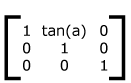
or [1 0 tan(a) 1 0 0], which has the effect
of skewing X coordinates by angle a.
- A skew
transformation along the y-axis is equivalent to the
matrix
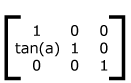
or [1 tan(a) 0 1 0 0], which has the effect
of skewing Y coordinates by angle a.
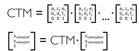
Transformations can be nested to any level. The effect of
nested transformations is to post-multiply (i.e., concatenate)
the subsequent transformation matrices onto previously defined
transformations:
For each given element, the accumulation of all
transformations that have been defined on the given element and
all of its ancestors up to and including the element that
established the current viewport (usually, the 'svg' element which is the most
immediate ancestor to the given element) is called the current transformation matrix or CTM. The CTM thus represents the
mapping of current user coordinates to viewport
coordinates:
Example 07_07 illustrates
nested transformations.
<?xml version="1.0" standalone="no"?>
<svg width="400px" height="150px" version="1.2" baseProfile="tiny"
     xmlns="http://www.w3.org/2000/svg">
  <desc>Example Nested - Nested transformations</desc>
  <g fill="none" stroke="black" stroke-width="3" >
    <!-- Draw the axes of the original coordinate system -->
    <line x1="0" y1="1.5" x2="400" y2="1.5" />
    <line x1="1.5" y1="0" x2="1.5" y2="150" />
  </g>
  <!-- First, a translate -->
  <g transform="translate(50,90)">
    <g fill="none" stroke="red" stroke-width="3" >
      <line x1="0" y1="0" x2="50" y2="0" />
      <line x1="0" y1="0" x2="0" y2="50" />
    </g>
    <text x="0" y="0" font-size="16" font-family="Verdana" >
      ....Translate(1)
    </text>
    <!-- Second, a rotate -->
    <g transform="rotate(-45)">
      <g fill="none" stroke="green" stroke-width="3" >
        <line x1="0" y1="0" x2="50" y2="0" />
        <line x1="0" y1="0" x2="0" y2="50" />
      </g>
      <text x="0" y="0" font-size="16" font-family="Verdana" >
        ....Rotate(2)
      </text>
      <!-- Third, another translate -->
      <g transform="translate(130,160)">
        <g fill="none" stroke="blue" stroke-width="3" >
          <line x1="0" y1="0" x2="50" y2="0" />
          <line x1="0" y1="0" x2="0" y2="50" />
        </g>
        <text x="0" y="0" font-size="16" font-family="Verdana" >
          ....Translate(3)
        </text>
      </g>
    </g>
  </g>
</svg>
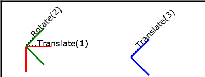
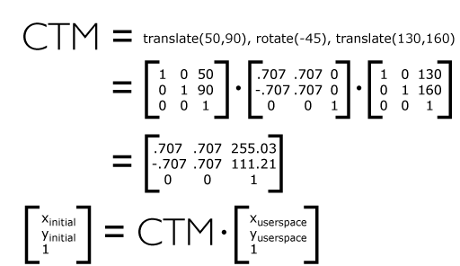
In the example above, the CTM within the third nested
transformation (i.e., the transform="translate(130,160)")
consists of the concatenation of the three transformations, as
follows:
transform = <transform-list> |
ref(svg [, <x>, <y>])
For the transform
attribute:
Animatable: yes.
See the 'animateTransform' element for
information on animating transformations.
The <transform-list> attribute type is
defined below. The 'ref( )' attribute type is
defined in the Constrained Transformations section.
A <transform-list> is defined as a
list of transform definitions, which are applied in the order
provided. The individual transform definitions are separated by
whitespace and/or a comma. The available types of transform
definitions include:
- matrix(<a> <b>
<c> <d> <e> <f>), which
specifies a transformation in the form of a transformation
matrix of six values. matrix(a,b,c,d,e,f) is equivalent
to applying the transformation matrix [a b c d e
f].
- translate(<tx>
[<ty>]), which specifies a translation by
tx and ty. If <ty> is not
provided, it is assumed to be zero.
- scale(<sx>
[<sy>]), which specifies a scale operation by
sx and sy. If <sy> is not
provided, it is assumed to be equal to
<sx>.
- rotate(<rotate-angle>
[<cx> <cy>]), which specifies a rotation by <rotate-angle> degrees about
a given point.
If optional parameters <cx> and <cy> are not supplied, the
rotate is about the origin of the current user coordinate
system. The operation corresponds to the matrix
[cos(a) sin(a) -sin(a) cos(a) 0 0].
If optional parameters <cx> and <cy> are supplied, the rotate
is about the point (<cx>,
<cy>). The operation represents the equivalent
of the following specification: translate(<cx>, <cy>)
rotate(<rotate-angle>) translate(-<cx>,
-<cy>).
- skewX(<skew-angle>), which
specifies a skew
transformation along the x-axis.
- skewY(<skew-angle>), which
specifies a skew
transformation along the y-axis.
All numeric values are real <number>s.
If a list of transforms is provided, then the net effect is
as if each transform had been specified separately in the order
provided. For example,
<g transform="translate(-10,-20) scale(2) rotate(45) translate(5,10)">
  <!-- graphics elements go here -->
</g>
is functionally equivalent to:
<g transform="translate(-10,-20)">
  <g transform="scale(2)">
    <g transform="rotate(45)">
      <g transform="translate(5,10)">
        <!-- graphics elements go here -->
      </g>
    </g>
  </g>
</g>
The transform attribute is
applied to an element before processing any other coordinate or
length values supplied for that element. In the element
<rect x="10" y="10" width="20" height="20" transform="scale(2)"/>
the x, y, width and height values are processed after the
current coordinate system has been scaled uniformly by a factor
of 2 by the transform attribute.
Attributes x, y, width and height (and any other attributes or
properties) are treated as values in the new user coordinate
system, not the previous user coordinate system. Thus, the
above 'rect' element is
functionally equivalent to:
<g transform="scale(2)">
  <rect x="10" y="10" width="20" height="20"/>
</g>
The following is the Backus-Naur Form (BNF) for values for
the transform attribute. The
following notation is used:
- *: 0 or more
- +: 1 or more
- ?: 0 or 1
- (): grouping
- |: separates alternatives
- double quotes surround literals
transform-list:
    wsp* transforms? wsp*
transforms:
    transform
    | transform comma-wsp+ transforms
transform:
    matrix
    | translate
    | scale
    | rotate
    | skewX
    | skewY
matrix:
    "matrix" wsp* "(" wsp*
       number comma-wsp
       number comma-wsp
       number comma-wsp
       number comma-wsp
       number comma-wsp
       number wsp* ")"
translate:
    "translate" wsp* "(" wsp* number ( comma-wsp number )? wsp* ")"
scale:
    "scale" wsp* "(" wsp* number ( comma-wsp number )? wsp* ")"
rotate:
    "rotate" wsp* "(" wsp* number ( comma-wsp number comma-wsp number )? wsp* ")"
skewX:
    "skewX" wsp* "(" wsp* number wsp* ")"
skewY:
    "skewY" wsp* "(" wsp* number wsp* ")"
number:
    sign? integer-constant
    | sign? floating-point-constant
comma-wsp:
    (wsp+ comma? wsp*) | (comma wsp*)
comma:
    ","
integer-constant:
    digit-sequence
floating-point-constant:
    fractional-constant exponent?
    | digit-sequence exponent
fractional-constant:
    digit-sequence? "." digit-sequence
    | digit-sequence "."
exponent:
    ( "e" | "E" ) sign? digit-sequence
sign:
    "+" | "-"
digit-sequence:
    digit
    | digit digit-sequence
digit:
    "0" | "1" | "2" | "3" | "4" | "5" | "6" | "7" | "8" | "9"
wsp:
    (#x20 | #x9 | #xD | #xA)
SVG 1.2 extends the coordinate system transformations allowed on groups
and elements to provide a method by which graphical objects can remain
fixed in the viewport without being scaled.
The following summarizes the different transforms that are applied to a graphical object as it is rendered.
The User Transform is the transformation that applies the user agent
positioning controls to the coordinate system. This transform can be
considered to be applied to a group that surrounds the outermost svg element of the document.
The user agent positioning controls consist of a translation (commonly
referred to as the "pan"), a scale (commonly referred to as the "zoom")
and a rotate.
US = User Scale (currentScale on SVGSVGElement)
UP = User Pan (currentTranslate on SVGSVGElement)
UR = User Rotate (currentRotate on SVGSVGElement)
The User Transform is the product of these component transformations.
U = User Transform
  = UP.US.UR
SVG elements, such as the root svg, create their own viewport. The viewBox to viewport transformation is the transformation on an svg element that adjusts the coordinate system to take the viewBox and preserveAspectRatio attributes into account.
We use the following notation for a viewBox to viewport transformation:
VB(svgId)
The 'svgId' parameter is the value of the id attribute on a given svg element.
All elements in an SVG document have a transform stack. This is the
list of transforms that manipulate the coordinate system between the
element and its nearest ancestor svg element.
We use the following notation for the Element Transform stack on a given element:
TS(id)
The 'id' parameter is the value of the id attribute on a given element.
<svg id="root">
<g id="g" transform="scale(2)">
<rect id="r" transform="scale(4)"/>
<g id="g2">
<rect id="r2" transform="scale(0.5)" />
</g>
</g>
</svg>
In this example, the transforms are:
TS(g) = scale(2)
TS(r) = TS(g) . scale(4) = scale(8)
TS(g2) = TS(g) . scale(2) = scale(4)
TS(r2) = TS(g) . scale(0.5) = scale(1)
Each element in the rendering tree has the concept of a Current
Transform Matrix, or CTM. This is the product of all coordinate system
transformations that apply to an element, effectively mapping the
element into a coordinate system that is then transformed into device
units by the user agent.
Consider the following example, with a rectangle having a set of ancestor g elements with ids "g-0" to "g-n" ("g-n" being the svg-root).
<svg id="g-n">
...
<g id="g-n-1">
...
...
<g id="g-2">
...
<g id="g-1">
...
<g id="g-0">
...
<rect id="elt" .../>
</g>
</g>
</g>
</g>
</svg>
With the above definitions, the CTM for the rectangle with id "elt" is:
CTM(elt) = prod{i=0, i=n}(U[i].VB(g[i]).TS(g[i-1])).TS(elt)

Where prod{i=1, i=n}(f(i)) as:
prod{i=0, i=n}(f(i)) = f(n).f(n-1).f(n-2).[...].f(1).f(0)
In the above definition, g[n] refers to the element with the id "g-n".
The TS() of a non-existent element is the identity transform. And:
U[i] = Identity for i < n and U[n] = U.
<svg id="g-2">
...
<g id="g-1">
...
<g id="g-0">
...
<rect id="elt" .../>
</g>
</g>
</svg>
This produces the following transformations:
CTM(elt) = U[2].VB(g[2]).TS(g[1])).U[1].VB(g[1]).TS(g[0]).U[0].VB(g[0]).TS(elt) =
= U.VB(g[2]).TS(g[1]).VB(g[1]).TS(g[0]).VB(g[0]).TS(elt)
Note the important relationship between an element's CTM and its parent CTM, for elements which do not define a viewport:
CTM(elt) = CTM(elt.parentElement).Txf(elt)
where Txf(elt) is the transform defined by the element's transform attribute.
By using the "ref()" attribute value on the transform attribute
it is possible to provide simple constrained transformations.
The 'ref(svg, x, y)' transform evaluates to the inverse of the element's parent's CTM multiplied by the svg element's CTM but exclusive of the svg element's zoom/pan/rotate user transform, if any.
The x and y
parameters are optional. If they are specified an additional
translation is appended to the transform so that (0, 0) in the
element's user space maps to (x, y) in the svg element's user space. If no x and y parameters are specified, no additional translation is applied.
Using the definitions provided above:
Inverse of the parent's CTM: inv(CTM(elt.parentElement))

The svg element's user transform, exclusive of zoom,
pan and rotate transforms:
   CTM(svg[0].parentElement).VB(svg[0])

CTM(svg[0].parentElement) evaluates to Identity since there
is no svg[0].parentElement element.
In addition, the T(x, y) translation is such that:
CTM(elt).(0, 0) = CTM(svg[0]).(x, y)
So the transform evaluates to:
Txf(elt) = inv(CTM(elt.parentElement)).CTM(svg[0].parentElement).VB(svg[0]).T(x, y)
The element's CTM is:
CTM(elt) = CTM(elt.parentElement).Txf(elt)
         = CTM(svg[0].parentElement).VB(svg[0]).T(x,y)
<svg id="root" viewBox="0 0 100 100">
<line x1="0" x2="100" y1="0" y2="100"/>
<rect id="r" transform="ref(svg)"
x="45" y="45" width="10" height="10"/>
</svg>
In this case:
Txf(r) = inv(CTM(r.parent)).CTM(root.parentElement).VB(root).T(x, y)

CTM(root.parentElement) evaluates to Identity.

T(x, y) evaluates to Identity because (x, y) is not specified

CTM(r) = CTM(r.parent).Txf(r)
= CTM(r.parent).inv(CTM(r.parent)).VB(root)
= VB(root)
= scale(2)
Consequently, regardless of the user transform (currentTranslate,
currentScale, currentRotate) the rectangle's coordinates in viewport
space will always
be: (45, 45, 10, 10)*scale(2) = (90, 90, 20, 20). Initially, the line
is from (0, 0) to (200, 200) in the viewport coordinate system. If we
apply a user agent zoom of 3 (currentScale = 3), the rectangle is still
(90, 90, 20, 20) but the line is (0, 0, 600, 600) and the marker no
longer marks the middle of the line.
<svg id="root" baseProfile="tiny" viewBox="0 0 100 100">
<line x1="0" x2="100" y1="0" y2="100"/>
<g id="g" transform="ref(svg, 50, 50)">
<rect id="r" x="-5" y="-5" width="10" height="10"/>
</g>
</svg>
In this case:
Txf(g) = inv(CTM(g.parent)).CTM(root.parentElement).VB(root).T(x,y)

CTM(root.parentElement) evaluates to Identity.

CTM(g) = CTM(g.parent).Txf(r)
= CTM(g.parent).inv(CTM(g.parent)).VB(root).T(x,y)
= VB(root).T(x,y)
= scale(2).T(x,y)
Initially, (50, 50) in the svg user space is (100, 100) in viewport space. Therefore:
CTM(g).[0, 0] = CTM(root).[50, 50]
= scale(2).[50, 50]
= [100, 100]

and

scale(2).T(x,y) = [100, 100]

T(x,y) = translate(50, 50)
If the user agent pan was (50, 80) (modifying currentTranslate) then we now have (50, 50) in the svg element's user space located at (150, 180) in the viewport space. This produces:
CTM(g).[0, 0] = CTM(root).[50, 50]
= translate(50, 80).scale(2).[50, 50]
= [150, 180]

and

scale(2).T(x,y) = [150, 180]

T(x, y) = translate(75, 90)
Therefore, regardless of the user transform, the rectangle will
always overlap the middle of the line. Note that the rectangle will not
rotate with the line (e.g., if currentRotate is set) and it will not
scale either.
7.8 The viewBox
attribute
It is often desirable to specify that a given set of
graphics stretch to fit a particular container element. The
viewBox attribute provides this
capability. All elements that establish a new viewport (see elements that
establish viewports) have attribute
viewBox.
Attribute definition:
-
viewBox = "<list> | 'none'
-
- <list>
- A list of four numbers <min-x>,
<min-y>,
<width> and
<height>, separated by
whitespace and/or a comma, which specify a rectangle in user
space which should be mapped to the bounds of the viewport
established by the given element, taking into account attribute
preserveAspectRatio. If specified,
an additional transformation is applied to all descendants of
the given element to achieve the specified effect.
- 'none'
- Specifying a value of 'none' indicates that no viewBox should be used. This is
exactly the same as not setting the viewBox at all.
Animatable:
yes.
A negative value for <width> or <height> is an error (see Error processing). A
value of zero disables rendering of the element.
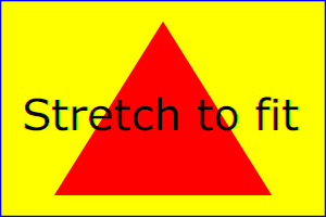
Example 07_12 illustrates
the use of the viewBox attribute
on the 'svg' element to specify that
the SVG content should stretch to fit bounds of the
viewport.
<?xml version="1.0" standalone="no"?>
<!DOCTYPE svg PUBLIC "-//W3C//DTD SVG 1.1//EN"
  "http://www.w3.org/Graphics/SVG/1.1/DTD/svg11.dtd">
<svg width="300px" height="200px" version="1.2" baseProfile="tiny"
     viewBox="0 0 1500 1000" preserveAspectRatio="none"
     xmlns="http://www.w3.org/2000/svg">
  <desc>Example ViewBox - uses the viewBox
   attribute to automatically create an initial user coordinate
   system which causes the graphic to scale to fit into the
   viewport no matter what size the viewport is.</desc>
  <!-- This rectangle goes from (0,0) to (1500,1000) in user space.
       Because of the viewBox attribute above,
       the rectangle will end up filling the entire area
       reserved for the SVG content. -->
  <rect x="0" y="0" width="1500" height="1000"
        fill="yellow" stroke="blue" stroke-width="12"  />
  <!-- A large, red triangle -->
  <path fill="red"  d="M 750,100 L 250,900 L 1250,900 z"/>
  <!-- A text string that spans most of the viewport -->
  <text x="100" y="600" font-size="200" font-family="Verdana" >
    Stretch to fit
  </text>
</svg>
 |
|
 |
Rendered into viewport with
width=300px, height=200px |
|
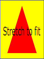
width=150px,
height=200px |
The effect of the viewBox
attribute is that the user agent automatically supplies the
appropriate transformation matrix to map the specified
rectangle in user space to the bounds of a designated region
(often, the viewport). To achieve the effect of the example on
the left, with viewport dimensions of 300 by 200 pixels, the
user agent needs to automatically insert a transformation which
scales both X and Y by 0.2. The effect is equivalent to having
a viewport of size 300px by 200px and the following
supplemental transformation in the document, as follows:
<svg width="300px" height="200px">
<g transform="scale(0.2)">
<!-- Rest of document goes here -->
</g>
</svg>
To achieve the effect of the example on the right, with
viewport dimensions of 150 by 200 pixels, the user agent needs
to automatically insert a transformation which scales X by 0.1
and Y by 0.2. The effect is equivalent to having a viewport of
size 150px by 200px and the following supplemental
transformation in the document, as follows:
<svg width="150px" height="200px">
<g transform="scale(0.1 0.2)">
<!-- Rest of document goes here -->
</g>
</svg>
(Note: in some cases the user agent will need to supply a
translate transformation in addition to a
scale transformation. For example, on an
'svg', a
translate transformation will be needed if the
viewBox attributes specifies
values other than zero for <min-x> or <min-y>.)
Unlike the transform attribute (see effect
of the transform on sibling
attributes), the automatic transformation that is created
due to a viewBox does not affect
the x, y, width and height attributes on the
element with the viewBox
attribute. Thus, in the example above which shows an 'svg' element which has attributes
width, height and viewBox, the width and height attributes represent values in
the coordinate system that exists before the viewBox transformation is applied. On
the other hand, like the transform attribute, it does
establish a new coordinate system for all other attributes and
for descendant elements.
7.9 The preserveAspectRatio
attribute
In some cases, typically when using the viewBox attribute, it is desirable
that the graphics stretch to fit non-uniformly to take up the
entire viewport. In other cases, it is desirable that uniform
scaling be used for the purposes of preserving the aspect ratio
of the graphics.
Attribute preserveAspectRatio="[defer] <align>
[<meetOrSlice>]", which is available for all
elements that establish a new viewport (see elements that
establish viewports), indicates
whether or not to force uniform scaling.
preserveAspectRatio only applies when
a value has been provided for viewBox on the same element. Or, in some cases, if an implicit
viewBox value can be established for the element (see each element description for details on
this). If a viewBox value can not be determined then
preserveAspectRatio is
ignored.
If the value of preserveAspectRatio on an element that references data ('image',
'animation' and 'video') starts with
'defer' then the value of the preserveAspectRatio attribute on the
referenced content if present should be used. If the
referenced content lacks a value for preserveAspectRatio then the preserveAspectRatio attribute should
be processed as normal (ignoring 'defer'). For preserveAspectRatio on all other
elements the 'defer' portion of the attribute is ignored.
The <align> parameter
indicates whether to force uniform scaling and, if so, the
alignment method to use in case the aspect ratio of the viewBox doesn't match the aspect
ratio of the viewport. The <align> parameter must be one
of the following strings:
- none - Do not force
uniform scaling. Scale the graphic content of the given
element non-uniformly if necessary such that the element's
bounding box exactly matches the viewport rectangle.
- xMinYMin - Force uniform
scaling.
Align the <min-x> of
the element's viewBox with the smallest X
value of the viewport.
Align the <min-y> of
the element's viewBox with the smallest Y
value of the viewport.
- xMidYMin - Force uniform
scaling.
Align the midpoint X value of the element's viewBox with the midpoint X
value of the viewport.
Align the <min-y> of
the element's viewBox with the smallest Y
value of the viewport.
- xMaxYMin - Force uniform
scaling.
Align the <min-x>+<width> of the
element's viewBox with the maximum X value
of the viewport.
Align the <min-y> of
the element's viewBox with the smallest Y
value of the viewport.
- xMinYMid - Force uniform
scaling.
Align the <min-x> of
the element's viewBox with the smallest X
value of the viewport.
Align the midpoint Y value of the element's viewBox with the midpoint Y
value of the viewport.
- xMidYMid (the default) -
Force uniform scaling.
Align the midpoint X value of the element's viewBox with the midpoint X
value of the viewport.
Align the midpoint Y value of the element's viewBox with the midpoint Y
value of the viewport.
- xMaxYMid - Force uniform
scaling.
Align the <min-x>+<width> of the
element's viewBox with the maximum X value
of the viewport.
Align the midpoint Y value of the element's viewBox with the midpoint Y
value of the viewport.
- xMinYMax - Force uniform
scaling.
Align the <min-x> of
the element's viewBox with the smallest X
value of the viewport.
Align the <min-y>+<height> of the
element's viewBox with the maximum Y value
of the viewport.
- xMidYMax - Force uniform
scaling.
Align the midpoint X value of the element's viewBox with the midpoint X
value of the viewport.
Align the <min-y>+<height> of the
element's viewBox with the maximum Y value
of the viewport.
- xMaxYMax - Force uniform
scaling.
Align the <min-x>+<width> of the
element's viewBox with the maximum X value
of the viewport.
Align the <min-y>+<height> of the
element's viewBox with the maximum Y value
of the viewport.
The <meetOrSlice>
parameter is optional and is only available due to historical reasons.
The <meetOrSlice> is separated from the
<align> value by one or
more spaces and must equal the string meet. This
is also the default value and therefore it is recommended that content do not
specify this parameter since it adds no additional value.
meet indicates to scale
the graphic such that:
- aspect ratio is preserved
- the entire viewBox is visible within
the viewport
- the viewBox is scaled up as much
as possible, while still meeting the other criteria
In this case, if the aspect ratio of the graphic does not
match the viewport, some of the viewport will extend beyond
the bounds of the viewBox (i.e., the area into
which the viewBox will draw will be
smaller than the viewport).
Example PreserveAspectRatio
illustrates the various options on preserveAspectRatio. The example
creates several new viewports by
including 'animation' elements (see Establishing a new
viewport).
Example PreserveAspectRatio
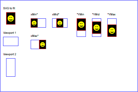 |
For the preserveAspectRatio
attribute:
Animatable: yes.
7.10 Establishing a new viewport
Some elements establish a new viewport. By establishing a new viewport, you
implicitly establish a new viewport coordinate system and a new
user coordinate system.
Additionally, there is a new meaning for percentage units
defined to be relative to the current viewport since a new
viewport has been established (see Units)
'viewport-fill' and
'viewport-fill-opacity' properties can
be applied on the new viewport.
The bounds of the new viewport are defined by the x, y,
width and height attributes on the element
establishing the new viewport, such as an 'animation' element. Both the new
viewport coordinate system and the new user coordinate system
have their origins at (x, y), where x and y
represent the value of the corresponding attributes on the
element establishing the viewport. The orientation of the new
viewport coordinate system and the new user coordinate system
correspond to the orientation of the current user coordinate
system for the element establishing the viewport. A single unit
in the new viewport coordinate system and the new user
coordinate system are the same size as a single unit in the
current user coordinate system for the element establishing the
viewport.
For an extensive example of creating new viewports, see Example
PreserveAspectRatio.
The following elements establish new viewports:
7.11 Units
Besides the exceptions listed below all coordinates and lengths
in SVG must be specified in user units, witch means that unit identifiers are not allowed.
Two exceptions exist:
- unit identifiers are allowed on the
'width' and 'height' attributes of the 'svg' element.
- Object bounding box units are allowed on 'linearGradient' and
'radialGradient' elements.
A user unit is a value in the current user
coordinate system. For example:
<text font-size="50">Text size is 50 user units</text>
For the svg element's 'width'and 'height' attributes
a coordinate or length value can be expressed
as a number following by a unit identifier (e.g., "25cm" or
"100%"). The list of unit identifiers in SVG are the following CSS unit identifiers:
in, cm, mm, pt, pc, px and percentages (%). The following describes how the various unit
identifiers are processed:
-
One px unit is defined to be equal to one user
unit. Thus, a length of "5px" is the same as a length of
"5".
-
The other absolute unit identifiers from CSS (i.e., pt,
pc, cm, mm, in) are all defined as an appropriate multiple
of one px unit (which, according to the previous
item, is defined to be equal to one user unit), based on
what the SVG user agent determines is the size of a
px unit (possibly passed from the parent processor
or environment at initialization time). For example,
suppose that the user agent can determine from its
environment that "1px" corresponds to "0.2822222mm" (i.e.,
90dpi). Then, for all processing:
- "1pt" equals "1.25px" (and therefore 1.25 user
units)
- "1pc" equals "15px" (and therefore 15 user
units)
- "1mm" would be "3.543307px" (3.543307 user
units)
- "1cm" equals "35.43307px" (and therefore 35.43307
user units)
- "1in" equals "90px" (and therefore 90 user
units)
Percentage values on 'width' and 'height' attributes mandates how much
space the SVG viewport should take of the available initial viewport.
See list below and initial viewport for details.
- For any width value expressed as a
percentage of the viewport, the value to use is the specified
percentage of the actual-width in user units for the
nearest containing viewport, where actual-width is
the width dimension of the viewport element within the user
coordinate system for the viewport element.
- For any height value expressed as a
percentage of the viewport, the value to use is the specified
percentage of the actual-height in user units for
the nearest containing viewport, where actual-height
is the height dimension of the viewport element within the
user coordinate system for the viewport element.
7.12 Object bounding box units
The following elements offer the option of expressing
coordinate values and lengths as fractions of
the bounding box
(via keyword objectBoundingBox)
on a given element:
| Element |
Attribute |
Effect |
| 'linearGradient' |
gradientUnits="objectBoundingBox" |
Indicates that the attributes which specify the
gradient vector (x1, y1, x2, y2) represent fractions of the bounding box of the element to which the
gradient is applied. |
| 'radialGradient' |
gradientUnits="objectBoundingBox" |
Indicates that the attributes which specify the center
(cx, cy) and the radius (r) represent fractions of the bounding box of the element to which the
gradient is applied. |
In the discussion that follows, the term applicable element is the element to
which the given effect applies. For gradients the
applicable element is the graphics element
which has its 'fill' or 'stroke' property referencing the
given gradient. (See Inheritance
of Painting Properties. For special rules concerning text elements, see the discussion of object
bounding box units and text elements.)
When keyword objectBoundingBox is used, then the
effect is as if a supplemental transformation matrix were
inserted into the list of nested transformation matrices to
create a new user coordinate system.
First, the (minx,miny) and
(maxx,maxy) coordinates are
determined for the applicable element and all of its
descendants. The values minx,
miny, maxx and
maxy are determined by computing the maximum
extent of the shape of the element in X and Y with respect to
the user coordinate system for the applicable element. The
bounding box is the tightest fitting rectangle aligned with the
axes of the applicable element's user coordinate system that
entirely encloses the applicable element and its descendants.
The bounding box is computed exclusive of any values for
opacity and stroke-width.
For curved shapes, the bounding box encloses all portions of
the shape, not just end points. For 'text' elements, for the
purposes of the bounding box calculation, each glyph is treated
as a separate graphics element. The calculations assume that
all glyphs occupy the full glyph cell. For example, for
horizontal text, the calculations assume that each glyph
extends vertically to the full ascent and descent values for
the font.
Then, coordinate (0,0) in the new user coordinate system is
mapped to the (minx,miny) corner of the tight bounding box
within the user coordinate system of the applicable element and
coordinate (1,1) in the new user coordinate system is mapped to
the (maxx,maxy) corner of the tight bounding box of the
applicable element. In most situations, the following
transformation matrix produces the correct effect:
[ (maxx-minx) 0 0 (maxy-miny) minx miny ]
Any numeric value can be specified for values expressed as a
fraction of object bounding box units. In
particular, fractions less are zero or greater than one can be
specified.
Keyword objectBoundingBox
should not be used when the geometry of the applicable element
has no width or no height, such as the case of a horizontal or
vertical line, even when the line has actual thickness when
viewed due to having a non-zero stroke width since stroke width
is ignored for bounding box calculations. When the geometry of
the applicable element has no width or height and objectBoundingBox is specified, then
the given effect (e.g., a gradient) will be
ignored.
7.13 Intrinsic Sizing Properties of the Viewport of SVG content
SVG must specify how to calculate some intrinsic sizing properties to
enable inclusion within other languages. The intrinsic width and height
of the viewport of SVG content is determined from the width and height
attributes. If these are not present the default values of 100% should
be used.
The intrinsic aspect ratio of the viewport of SVG content is necessary
for example when including SVG from an object tag in XHTML styled with
CSS. The intrinsic aspect ratio should be calculated based upon the
following rules:
- If the width and height of the root SVG element are both specified in
absolute units (in, mm, cm, pt, pc, px) then the aspect ratio is
calculated from the width and height after resolving both values to the
same units.
- If either/both of the width and height of the root svg are in
percentage units, the aspect ratio is calculated from the width and
height of the viewBox. If the viewBox is not present, or set to 'none',
the intrinsic aspect ratio cannot be calculated and is unspecified.
Examples:
<svg width="10cm" height="5cm">
...
</svg>
In this example the intrinsic aspect ratio of the viewport is 2:1. The
intrinsic width is 10cm and the intrinsic height is 5cm.
<svg width="100%" height="50%" viewBox="0 0 200 200">
...
</svg>
In this example the intrinsic aspect ratio of the outermost viewport is
1:1. An aspect ratio calculation in this case allows embedding in an
object within a containing block that is only constrained in one direction.
<svg width="10cm" viewBox="0 0 200 200">
...
</svg>
In this case the intrinsic aspect ratio is 1:1.
<width="75%" height="10cm" viewbox="0 0 200 200">
...
</svg>
In this example, the intrinsic aspect ratio is 1:1.
7.14 Geographic Coordinate Systems
In order to allow interoperability between SVG content
generators and user agents dealing with maps encoded in SVG,
SVG encourages the use of a common metadata definition for
describing the coordinate system used to generate SVG
documents.
Such metadata should be added under the 'metadata' element of the topmost
'svg' element describing the
map. They consist of an RDF description of the Coordinate
Reference System definition used to generate the SVG map.
The definition should be conformant to the XML grammar
described in the OpenGIS Recommendation on the Definition of
Coordinate Reference System [OpenGIS
Coordinate Systems]. In order to correctly map the
2-dimensional data used by SVG, the CRS must be of subtype
ProjectedCRS or Geographic2dCRS. The first axis of the
described CRS maps the SVG x-axis and the second axis maps the
SVG y-axis. Optionally, an additional affine transformation may
have been applied during this mapping. This additional
transformation is described by an SVG transform attribute that can be added
to the OpenGIS 'CoordinateReferenceSystem'
element. Note that the transform
attribute on the 'CoordinateReferenceSystem' does
not indicate that a transformation should be applied to the
data within the file, it simply describes the transformation
that was applied to the data when being encoded in SVG.
There are three typical uses for the SVG transform
attribute. These are described below and used in the
examples.
- Most ProjectedCRS have the north direction represented by
positive values of the second axis and conversely SVG has a
y-down coordinate system. That's why, in order to follow the
usual way to represent a map with the north at its top, it is
recommended for that kind of ProjectedCRS to use the SVG
transform attribute with a 'scale(1, -1)' value as in the
third example below.
- Most Geographic2dCRS have the latitude as their first
axis rather than the longitude, which means that the
south-north axis would be represented by the x-axis in SVG
instead of the usual y-axis. That's why, in order to follow
the usual way to represent a map with the north at its top,
it is recommended for that kind of Geographic2dCRS to use the
SVG transform attribute with a 'rotate(-90)' value as in the
first example (while also adding the scale(1, -1) as for
ProjectedCRS).
- In addition, when converting for profiles which place
restrictions on precision of real number values, it may be
useful to add an additional scaling factor to retain good
precision for a specific area. When generating an SVG
document from WGS84 geographic coordinates (EPGS 4326), we
recommend the use of an additional 100 times scaling factor
corresponding to an SVG transform attribute with a
'rotate(-90) scale(100)' value (shown in the second example).
Different scaling values may be required depending on the
particular CRS.
The main purpose of such metadata is to indicate to the User
Agent that two or more SVG documents can be overlayed or merged
into a single document. Obviously, if two maps reference the
same Coordinate Reference System definition and have the same
SVG transform attribute value then they can be overlayed
without reprojecting the data. If the maps reference different
Coordinate Reference Systems and/or have different SVG
transform attribute values, then a specialized cartographic
User Agent may choose to transform the coordinate data to
overlay the data. However, typical SVG user agents are not
required to perform these types of transformations, or even
recognize the metadata.
Below is a simple example of the coordinate metadata, which
describes the coordinate system used by the document via a
URI.
<?xml version="1.0"?>
<svg width="100" height="100" viewBox="0 0 1000 1000" version="1.2"
     xmlns="http://www.w3.org/2000/svg" baseProfile="tiny">
     <desc>An example that references co-ordinate data.</desc>
    <metadata>
      <rdf:RDF xmlns:rdf = "http://www.w3.org/1999/02/22-rdf-syntax-ns#"
               xmlns:crs = "http://www.ogc.org/crs"
               xmlns:svg="http://wwww.w3.org/2000/svg">
        <rdf:Description>
          <!-- The Coordinate Reference System is described
               through an URI. -->
          <crs:CoordinateReferenceSystem svg:transform="rotate(-90)"
                 rdf:resource=""http://www.example.org/srs/epsg.xml#4326"/>
        </rdf:Description>
      </rdf:RDF>
    </metadata>
    <!-- The actual map content -->
</svg>
The second example uses a well-known identifier to describe
the coordinate system. Note that the coordinates used in the
document have had the supplied transform applied.
<?xml version="1.0"?>
<svg width="100" height="100" viewBox="0 0 1000 1000" version="1.2"
     xmlns="http://www.w3.org/2000/svg" baseProfile="tiny">
     <desc>Example using a well known co-ordinate system.</desc>
    <metadata>
      <rdf:RDF xmlns:rdf = "http://www.w3.org/1999/02/22-rdf-syntax-ns#"
               xmlns:crs = "http://www.ogc.org/crs"
               xmlns:svg="http://wwww.w3.org/2000/svg">
        <rdf:Description>
          <!-- In case of a well-known Coordinate Reference System
               an 'Identifier' is enough to describe the CRS -->
          <crs:CoordinateReferenceSystem svg:transform="rotate(-90) scale(100, 100)">
            <crs:Identifier>
              <crs:code>4326</crs:code>
              <crs:codeSpace>EPSG</crs:codeSpace>
              <crs:edition>5.2</crs:edition>
            </crs:Identifier>
          </crs:CoordinateReferenceSystem>
        </rdf:Description>
      </rdf:RDF>
    </metadata>
    <!-- The actual map content -->
</svg>
The third example defines the coordinate system completely
within the SVG document.
<?xml version="1.0"?>
<svg width="100" height="100" viewBox="0 0 1000 1000" version="1.2"
    xmlns="http://www.w3.org/2000/svg" baseProfile="tiny">
    <desc>Co-ordinate Metadata defined within the SVG Document</desc>
    <metadata>
      <rdf:RDF xmlns:rdf="http://www.w3.org/1999/02/22-rdf-syntax-ns#"
               xmlns:crs="http://www.ogc.org/crs"
               xmlns:svg="http://wwww.w3.org/2000/svg">
        <rdf:Description>
          <!-- For other CRS it should be entirely defined -->
          <crs:CoordinateReferenceSystem svg:transform="scale(1,-1)">
            <crs:NameSet>
              <crs:name>Mercator projection of WGS84</crs:name>
            </crs:NameSet>
            <crs:ProjectedCRS>
              <!-- The actual definition of the CRS -->
              <crs:CartesianCoordinateSystem>
                <crs:dimension>2</crs:dimension>
                <crs:CoordinateAxis>
                  <crs:axisDirection>north</crs:axisDirection>
                  <crs:AngularUnit>
                    <crs:Identifier>
                      <crs:code>9108</crs:code>
                      <crs:codeSpace>EPSG</crs:codeSpace>
                      <crs:edition>5.2</crs:edition>
                    </crs:Identifier>
                  </crs:AngularUnit>
                </crs:CoordinateAxis>
                <crs:CoordinateAxis>
                  <crs:axisDirection>east</crs:axisDirection>
                  <crs:AngularUnit>
                    <crs:Identifier>
                      <crs:code>9108</crs:code>
                      <crs:codeSpace>EPSG</crs:codeSpace>
                      <crs:edition>5.2</crs:edition>
                    </crs:Identifier>
                  </crs:AngularUnit>
                </crs:CoordinateAxis>
              </crs:CartesianCoordinateSystem>
              <crs:CoordinateReferenceSystem>
                <!-- the reference system of that projected system is
                           WGS84 which is EPSG 4326 in EPSG codeSpace -->
                <crs:NameSet>
                  <crs:name>WGS 84</crs:name>
                </crs:NameSet>
                <crs:Identifier>
                  <crs:code>4326</crs:code>
                  <crs:codeSpace>EPSG</crs:codeSpace>
                  <crs:edition>5.2</crs:edition>
                </crs:Identifier>
              </crs:CoordinateReferenceSystem>
              <crs:CoordinateTransformationDefinition>
                <crs:sourceDimensions>2</crs:sourceDimensions>
                <crs:targetDimensions>2</crs:targetDimensions>
                <crs:ParameterizedTransformation>
                  <crs:TransformationMethod>
                    <!-- the projection is a Mercator projection which is
                          EPSG 9805 in EPSG codeSpace -->
                    <crs:NameSet>
                      <crs:name>Mercator</crs:name>
                    </crs:NameSet>
                    <crs:Identifier>
                      <crs:code>9805</crs:code>
                      <crs:codeSpace>EPSG</crs:codeSpace>
                      <crs:edition>5.2</crs:edition>
                    </crs:Identifier>
                    <crs:description>Mercator (2SP)</crs:description>
                  </crs:TransformationMethod>
                  <crs:Parameter>
                    <crs:NameSet>
                      <crs:name>Latitude of 1st standart parallel</crs:name>
                    </crs:NameSet>
                    <crs:Identifier>
                      <crs:code>8823</crs:code>
                      <crs:codeSpace>EPSG</crs:codeSpace>
                      <crs:edition>5.2</crs:edition>
                    </crs:Identifier>
                    <crs:value>0</crs:value>
                  </crs:Parameter>
                  <crs:Parameter>
                    <crs:NameSet>
                      <crs:name>Longitude of natural origin</crs:name>
                    </crs:NameSet>
                    <crs:Identifier>
                      <crs:code>8802</crs:code>
                      <crs:codeSpace>EPSG</crs:codeSpace>
                      <crs:edition>5.2</crs:edition>
                    </crs:Identifier>
                    <crs:value>0</crs:value>
                  </crs:Parameter>
                  <crs:Parameter>
                    <crs:NameSet>
                      <crs:name>False Easting</crs:name>
                    </crs:NameSet>
                    <crs:Identifier>
                      <crs:code>8806</crs:code>
                      <crs:codeSpace>EPSG</crs:codeSpace>
                      <crs:edition>5.2</crs:edition>
                    </crs:Identifier>
                    <crs:value>0</crs:value>
                  </crs:Parameter>
                  <crs:Parameter>
                    <crs:NameSet>
                      <crs:name>False Northing</crs:name>
                    </crs:NameSet>
                    <crs:Identifier>
                      <crs:code>8807</crs:code>
                      <crs:codeSpace>EPSG</crs:codeSpace>
                      <crs:edition>5.2</crs:edition>
                    </crs:Identifier>
                    <crs:value>0</crs:value>
                  </crs:Parameter>
                </crs:ParameterizedTransformation>
              </crs:CoordinateTransformationDefinition>
            </crs:ProjectedCRS>
          </crs:CoordinateReferenceSystem>
        </rdf:Description>
      </rdf:RDF>
    </metadata>
    <!-- the actual map content -->
</svg>