8 Paths
8.1 Introduction
Paths represent the outline of a shape which can be filled or
stroked. (See Filling, Stroking and Paint
Servers.)
A path is described using the concept of a current point. In
an analogy with drawing on paper, the current point can be
thought of as the location of the pen. The position of the pen
can be changed, and the outline of a shape (open or closed) can
be traced by dragging the pen in either straight lines or
curves.
Paths represent the geometry of the outline of an object,
defined in terms of moveto (set a new current point),
lineto (draw a straight line), curveto (draw
a curve using a cubic Bézier) and closepath (close the current
shape by drawing a line to the last moveto) elements.
Compound paths (i.e., a path with multiple subpaths) are
possible to allow effects such as "donut holes" in objects.
This chapter describes the syntax and behavior for SVG paths.
Various implementation notes for SVG
paths can be found in 'path' element implementation
notes.
A path is defined in SVG using the 'path' element.
8.2 The 'path'
element
  <define name='path'>
    <element name='path'>
      <ref name='path.AT'/>
      <zeroOrMore><ref name='shapeCommon.CM'/></zeroOrMore>
    </element>
  </define>

  <define name='path.AT' combine='interleave'>
    <ref name='svg.ShapeCommon.attr'/>
    <ref name='svg.D.attr'/>
    <optional>
      <attribute name='pathLength' svg:animatable='true' svg:inheritable='false'>
        <ref name='Number.datatype'/>
      </attribute>
    </optional>
  </define>
Attribute definitions:
- d = "path data"
- The definition of the outline of a shape. See Path data.
Animatable: yes.
Path data animation is only possible when each path data
specification within an animation specification has exactly
the same list of path data commands as the d attribute. If an animation is
specified and the list of path data commands is not the
same, then the animation specification is in error (see Error Processing).
The animation engine interpolates each parameter to each
path data command separately based on the attributes to the
given animation element. Flags and booleans are
interpolated as fractions between zero and one, with any
non-zero value considered to be a value of one/true.
- pathLength = "<number>"
- The author's computation of the total length of the
path, in user units. This value is used to calibrate the
user agent's own distance-along-a-path
calculations with that of the author. The user agent will
scale all distance-along-a-path computations by the ratio
of pathLength to the user
agent's own computed value for total path length. pathLength potentially affects
calculations for motion
animation and various stroke
operations.
A negative value is an error (see Error
processing).
Animatable:
yes.
8.3 Path data
A path is defined by including a 'path'
element which contains a d="(path data)"
attribute, where the d attribute contains the
moveto, line, curve (both cubic and
quadratic Béziers) and closepath
instructions.
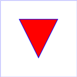
Example 08_01
specifies a path in the shape of a triangle. (The
M indicates a moveto, the
L's indicate lineto's, and the
z indicates a closepath).
<?xml version="1.0" standalone="no"?>
<svg width="4cm" height="4cm" viewBox="0 0 400 400"
     xmlns="http://www.w3.org/2000/svg" version="1.1" baseProfile="tiny">
  <title>Example triangle01- simple example of a 'path'</title>
  <desc>A path that draws a triangle</desc>
  <rect x="1" y="1" width="398" height="398"
        fill="none" stroke="blue" />
  <path d="M 100 100 L 300 100 L 200 300 z"
        fill="red" stroke="blue" stroke-width="3" />
</svg>
Path data can contain newline characters and thus can be
broken up into multiple lines to improve readability. Because
of line length limitations with certain related tools, it is
recommended that SVG generators split long path data strings
across multiple lines, with each line not exceeding 255
characters. Also note that newline characters are only allowed
at certain places within path data.
The syntax of path data is concise in order to allow for
minimal file size and efficient downloads, since many SVG files
will be dominated by their path data. Some of the ways that SVG
attempts to minimize the size of path data are as follows:
- All instructions are expressed as one character (e.g., a
moveto is expressed as an M).
- Superfluous white space and separators such as commas can
be eliminated (e.g., "M 100 100 L 200 200" contains
unnecessary spaces and could be expressed more compactly as
"M100 100L200 200").
- The command letter can be eliminated on subsequent
commands if the same command is used multiple times in a row
(e.g., you can drop the second "L" in "M 100 200 L 200 100 L
-100 -200" and use "M 100 200 L 200 100 -100 -200"
instead).
- Relative versions of all commands are available
(uppercase means absolute coordinates, lowercase means
relative coordinates).
- Alternate forms of lineto are available to
optimize the special cases of horizontal and vertical lines
(absolute and relative).
- Alternate forms of curve are available to
optimize the special cases where some of the control points
on the current segment can be determined automatically from
the control points on the previous segment.
The path data syntax is a prefix notation (i.e., commands
followed by parameters). The only allowable decimal point is a
Unicode [UNICODE]
FULL STOP (".") character (also referred to in Unicode as
PERIOD, dot and decimal point) and no other delimiter
characters are allowed. (For example, the following is an
invalid numeric value in a path data stream: "13,000.56".
Instead, say: "13000.56".)
For the relative versions of the commands, all coordinate
values are relative to the current point at the start of the
command.
In the tables below, the following notation is used:
- (): grouping of parameters
- +: 1 or more of the given parameter(s) is required
The following sections list the commands.
8.3.2 The "moveto" commands
The "moveto" commands (M or
m) establish a new current point. The effect
is as if the "pen" were lifted and moved to a new location. A
path data segment (if there is one) must begin with a "moveto"
command. Subsequent "moveto" commands (i.e., when the "moveto"
is not the first command) represent the start of a new
subpath:
| Command |
Name |
Parameters |
Description |
M (absolute)
m (relative) |
moveto |
(x y)+ |
Start a new sub-path at the given (x,y) coordinate.
M (uppercase) indicates that absolute
coordinates will follow; m (lowercase)
indicates that relative coordinates will follow. If a
relative moveto (m) appears as the first
element of the path, then it is treated as a pair of
absolute coordinates. If a moveto is followed by multiple
pairs of coordinates, the subsequent pairs are treated as
implicit lineto commands. |
8.3.3 The "closepath" command
The "closepath" (Z or z)
ends the current subpath and causes an automatic straight line
to be drawn from the current point to the initial point of the
current subpath. If a "closepath" is followed immediately by a
"moveto", then the "moveto" identifies the start point of the
next subpath. If a "closepath" is followed immediately by any
other command, then the next subpath starts at the same initial
point as the current subpath.
When a subpath ends in a "closepath," it differs in behavior
from what happens when "manually" closing a subpath via a
"lineto" command in how 'stroke-linejoin'
and 'stroke-linecap'
are implemented. With "closepath", the end of the final segment
of the subpath is "joined" with the start of the initial
segment of the subpath using the current value of 'stroke-linejoin'.
If you instead "manually" close the subpath via a "lineto"
command, the start of the first segment and the end of the last
segment are not joined but instead are each capped using the
current value of 'stroke-linecap'.
At the end of the command, the new current point is set to the
initial point of the current subpath.
| Command |
Name |
Parameters |
Description |
Z or
z |
closepath |
(none) |
Close the current subpath by drawing a straight line
from the current point to current subpath's initial
point. |
8.3.4 The "lineto" commands
The various "lineto" commands draw straight lines from the
current point to a new point:
| Command |
Name |
Parameters |
Description |
L (absolute)
l (relative) |
lineto |
(x y)+ |
Draw a line from the current point to the given (x,y)
coordinate which becomes the new current point.
L (uppercase) indicates that absolute
coordinates will follow; l (lowercase)
indicates that relative coordinates will follow. A number
of coordinates pairs may be specified to draw a polyline.
At the end of the command, the new current point is set to
the final set of coordinates provided. |
H (absolute)
h (relative) |
horizontal lineto |
x+ |
Draws a horizontal line from the current point (cpx,
cpy) to (x, cpy). H (uppercase) indicates
that absolute coordinates will follow; h
(lowercase) indicates that relative coordinates will
follow. Multiple x values can be provided (although usually
this doesn't make sense). At the end of the command, the
new current point becomes (x, cpy) for the final value of
x. |
V (absolute)
v (relative) |
vertical lineto |
y+ |
Draws a vertical line from the current point (cpx, cpy)
to (cpx, y). V (uppercase) indicates that
absolute coordinates will follow; v
(lowercase) indicates that relative coordinates will
follow. Multiple y values can be provided (although usually
this doesn't make sense). At the end of the command, the
new current point becomes (cpx, y) for the final value of
y. |
8.3.5 The curve commands
These groups of commands draw curves:
- Cubic
Bézier commands (C,
c, S and
s). A cubic Bézier segment is defined
by a start point, an end point, and two control points.
- Quadratic
Bézier commands (Q,
q, T and
t). A quadratic Bézier segment is
defined by a start point, an end point, and one control
point.
8.3.6 The cubic Bézier curve commands
The cubic Bézier commands are as follows:
| Command |
Name |
Parameters |
Description |
C (absolute)
c (relative) |
curveto |
(x1 y1 x2 y2 x y)+ |
Draws a cubic Bézier curve from the current
point to (x,y) using (x1,y1) as the control point at the
beginning of the curve and (x2,y2) as the control point at
the end of the curve. C (uppercase)
indicates that absolute coordinates will follow;
c (lowercase) indicates that relative
coordinates will follow. Multiple sets of coordinates may
be specified to draw a polybézier. At the end of the
command, the new current point becomes the final (x,y)
coordinate pair used in the polybézier. |
S (absolute)
s (relative) |
shorthand/smooth curveto |
(x2 y2 x y)+ |
Draws a cubic Bézier curve from the current
point to (x,y). The first control point is assumed to be
the reflection of the second control point on the previous
command relative to the current point. (If there is no
previous command or if the previous command was not an C,
c, S or s, assume the first control point is coincident
with the current point.) (x2,y2) is the second control
point (i.e., the control point at the end of the curve).
S (uppercase) indicates that absolute
coordinates will follow; s (lowercase)
indicates that relative coordinates will follow. Multiple
sets of coordinates may be specified to draw a
polybézier. At the end of the command, the new
current point becomes the final (x,y) coordinate pair used
in the polybézier. |
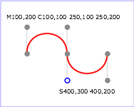
Example 08_02 shows some
simple uses of cubic Bézier commands within a path. The
example uses an internal CSS style sheet to assign styling
properties. Note that the control point for the "S" command is
computed automatically as the reflection of the control point
for the previous "C" command relative to the start point of the
"S" command.
<?xml version="1.0" standalone="no"?>
<svg width="5cm" height="4cm" viewBox="0 0 500 400"
     xmlns="http://www.w3.org/2000/svg" version="1.2" baseProfile="tiny">
  <title>Example cubic01- cubic Bézier commands in path data</title>
  <desc>Picture showing a simple example of path data
        using both a "C" and an "S" command,
        along with annotations showing the control points
        and end points</desc>
  <rect fill="none" stroke="blue" stroke-width="1" x="1" y="1" width="498" height="398" />
  <polyline fill="none" stroke="#888888" stroke-width="1" points="100,200 100,100" />
  <polyline fill="none" stroke="#888888" stroke-width="1" points="250,100 250,200" />
  <polyline fill="none" stroke="#888888" stroke-width="1" points="250,200 250,300" />
  <polyline fill="none" stroke="#888888" stroke-width="1" points="400,300 400,200" />
  <path fill="none" stroke="red" stroke-width="5" d="M100,200 C100,100 250,100 250,200
                                       S400,300 400,200" />
  <circle fill="#888888" stroke="none" stroke-width="2" cx="100" cy="200" r="10" />
  <circle fill="#888888" stroke="none" stroke-width="2" cx="250" cy="200" r="10" />
  <circle fill="#888888" stroke="none" stroke-width="2" cx="400" cy="200" r="10" />
  <circle fill="#888888" stroke="none" cx="100" cy="100" r="10" />
  <circle fill="#888888" stroke="none" cx="250" cy="100" r="10" />
  <circle fill="#888888" stroke="none" cx="400" cy="300" r="10" />
  <circle fill="none" stroke="blue" stroke-width="4" cx="250" cy="300" r="9" />
  <text font-size="22" font-family="Verdana" x="25" y="70">M100,200 C100,100 250,100 250,200</text>
  <text font-size="22" font-family="Verdana" x="325" y="350"
        text-anchor="middle">S400,300 400,200</text>
</svg>
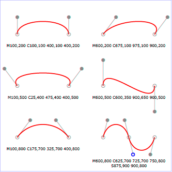
The following picture shows some how cubic Bézier
curves change their shape depending on the position of the
control points. The first five examples illustrate a single
cubic Bézier path segment. The example at the lower
right shows a "C" command followed by an "S" command.
View
this example as SVG (SVG-enabled browsers only)
8.3.7 The quadratic Bézier curve commands
The quadratic Bézier commands are as follows:
| Command |
Name |
Parameters |
Description |
Q (absolute)
q (relative) |
quadratic Bézier curveto |
(x1 y1 x y)+ |
Draws a quadratic Bézier curve from the current
point to (x,y) using (x1,y1) as the control point.
Q (uppercase) indicates that absolute
coordinates will follow; q (lowercase)
indicates that relative coordinates will follow. Multiple
sets of coordinates may be specified to draw a
polybézier. At the end of the command, the new
current point becomes the final (x,y) coordinate pair used
in the polybézier. |
T (absolute)
t (relative) |
Shorthand/smooth quadratic Bézier curveto |
(x y)+ |
Draws a quadratic Bézier curve from the current
point to (x,y). The control point is assumed to be the
reflection of the control point on the previous command
relative to the current point. (If there is no previous
command or if the previous command was not a Q, q, T or t,
assume the control point is coincident with the current
point.) T (uppercase) indicates that
absolute coordinates will follow; t
(lowercase) indicates that relative coordinates will
follow. At the end of the command, the new current point
becomes the final (x,y) coordinate pair used in the
polybézier. |
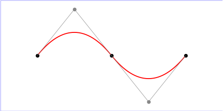
Example quad01 shows some
simple uses of quadratic Bézier commands within a path.
Note that the control point for the "T" command is computed
automatically as the reflection of the control point for the
previous "Q" command relative to the start point of the "T"
command.
<?xml version="1.0" standalone="no"?>
<!DOCTYPE svg PUBLIC "-//W3C//DTD SVG 1.1//EN"
  "http://www.w3.org/Graphics/SVG/1.1/DTD/svg11.dtd">
<svg width="12cm" height="6cm" viewBox="0 0 1200 600"
     xmlns="http://www.w3.org/2000/svg" version="1.2" baseProfile="tiny">
  <title>Example quad01 - quadratic Bezier commands in path data</title>
  <desc>Picture showing a "Q" a "T" command,
        along with annotations showing the control points
        and end points</desc>
  <rect x="1" y="1" width="1198" height="598"
        fill="none" stroke="blue" stroke-width="1" />
  <path d="M200,300 Q400,50 600,300 T1000,300"
        fill="none" stroke="red" stroke-width="5"  />
  <!-- End points -->
  <g fill="black" >
    <circle cx="200" cy="300" r="10"/>
    <circle cx="600" cy="300" r="10"/>
    <circle cx="1000" cy="300" r="10"/>
  </g>
  <!-- Control points and lines from end points to control points -->
  <g fill="#888888" >
    <circle cx="400" cy="50" r="10"/>
    <circle cx="800" cy="550" r="10"/>
  </g>
  <path d="M200,300 L400,50 L600,300
           L800,550 L1000,300"
        fill="none" stroke="#888888" stroke-width="2" />
</svg>
8.3.8 The grammar for path data
The following notation is used in the Backus-Naur Form (BNF)
description of the grammar for path data:
- *: 0 or more
- +: 1 or more
- ?: 0 or 1
- (): grouping
- |: separates alternatives
- double quotes surround literals
The following is the BNF for SVG paths.
svg-path:
    wsp* moveto-drawto-command-groups? wsp*
moveto-drawto-command-groups:
    moveto-drawto-command-group
    | moveto-drawto-command-group wsp* moveto-drawto-command-groups
moveto-drawto-command-group:
    moveto wsp* drawto-commands?
drawto-commands:
    drawto-command
    | drawto-command wsp* drawto-commands
drawto-command:
    closepath
    | lineto
    | horizontal-lineto
    | vertical-lineto
    | curveto
    | smooth-curveto
    | quadratic-bezier-curveto
    | smooth-quadratic-bezier-curveto
moveto:
    ( "M" | "m" ) wsp* moveto-argument-sequence
moveto-argument-sequence:
    coordinate-pair
    | coordinate-pair comma-wsp? lineto-argument-sequence
closepath:
    ("Z" | "z")
lineto:
    ( "L" | "l" ) wsp* lineto-argument-sequence
lineto-argument-sequence:
    coordinate-pair
    | coordinate-pair comma-wsp? lineto-argument-sequence
horizontal-lineto:
    ( "H" | "h" ) wsp* horizontal-lineto-argument-sequence
horizontal-lineto-argument-sequence:
    coordinate
    | coordinate comma-wsp? horizontal-lineto-argument-sequence
vertical-lineto:
    ( "V" | "v" ) wsp* vertical-lineto-argument-sequence
vertical-lineto-argument-sequence:
    coordinate
    | coordinate comma-wsp? vertical-lineto-argument-sequence
curveto:
    ( "C" | "c" ) wsp* curveto-argument-sequence
curveto-argument-sequence:
    curveto-argument
    | curveto-argument comma-wsp? curveto-argument-sequence
curveto-argument:
    coordinate-pair comma-wsp? coordinate-pair comma-wsp? coordinate-pair
smooth-curveto:
    ( "S" | "s" ) wsp* smooth-curveto-argument-sequence
smooth-curveto-argument-sequence:
    smooth-curveto-argument
    | smooth-curveto-argument comma-wsp? smooth-curveto-argument-sequence
smooth-curveto-argument:
    coordinate-pair comma-wsp? coordinate-pair
quadratic-bezier-curveto:
    ( "Q" | "q" ) wsp* quadratic-bezier-curveto-argument-sequence
quadratic-bezier-curveto-argument-sequence:
    quadratic-bezier-curveto-argument
    | quadratic-bezier-curveto-argument comma-wsp?
        quadratic-bezier-curveto-argument-sequence
quadratic-bezier-curveto-argument:
    coordinate-pair comma-wsp? coordinate-pair
smooth-quadratic-bezier-curveto:
    ( "T" | "t" ) wsp* smooth-quadratic-bezier-curveto-argument-sequence
smooth-quadratic-bezier-curveto-argument-sequence:
    coordinate-pair
    | coordinate-pair comma-wsp? smooth-quadratic-bezier-curveto-argument-sequence
coordinate-pair:
    coordinate comma-wsp? coordinate
coordinate:
    number
nonnegative-number:
    integer-constant
    | floating-point-constant
number:
    sign? integer-constant
    | sign? floating-point-constant
flag:
    "0" | "1"
comma-wsp:
    (wsp+ comma? wsp*) | (comma wsp*)
comma:
    ","
integer-constant:
    digit-sequence
floating-point-constant:
    fractional-constant exponent?
    | digit-sequence exponent
fractional-constant:
    digit-sequence? "." digit-sequence
    | digit-sequence "."
exponent:
    ( "e" | "E" ) sign? digit-sequence
sign:
    "+" | "-"
digit-sequence:
    digit
    | digit digit-sequence
digit:
    "0" | "1" | "2" | "3" | "4" | "5" | "6" | "7" | "8" | "9"
wsp:
    (#x20 | #x9 | #xD | #xA)
The processing of the BNF must consume as much of a given
BNF production as possible, stopping at the point when a
character is encountered which no longer satisfies the
production. Thus, in the string "M 100-200", the first
coordinate for the "moveto" consumes the characters "100" and
stops upon encountering the minus sign because the minus sign
cannot follow a digit in the production of a "coordinate". The
result is that the first coordinate will be "100" and the
second coordinate will be "-200".
Similarly, for the string "M 0.6.5", the first coordinate of
the "moveto" consumes the characters "0.6" and stops upon
encountering the second decimal point because the production of
a "coordinate" only allows one decimal point. The result is
that the first coordinate will be "0.6" and the second
coordinate will be ".5".
Note that the BNF allows the path 'd' attribute to be empty. This is not
an error, instead it disables rendering of the path.
8.4 Distance along a path
Various operations, including motion animation
and various stroke
operations, require that the user agent compute the
distance along the geometry of a graphics element, such as a
'path'.
Exact mathematics exist for computing distance along a path,
but the formulas are highly complex and require substantial
computation. It is recommended that authoring products and user
agents employ algorithms that produce as precise results as
possible; however, to accommodate implementation differences
and to help distance calculations produce results that
approximate author intent, the pathLength attribute can be used
to provide the author's computation of the total length of the
path so that the user agent can scale distance-along-a-path
computations by the ratio of pathLength to the user agent's own
computed value for total path length.
A "moveto" operation within a 'path' element is defined to have
zero length. Only the various "lineto" and "curveto" commands
contribute to path length calculations.