1. Introduction
There are a handful of different motion sensors available in modern hardware such as phones.
The motion sensors extends the Generic Sensor API [GENERIC-SENSOR] to expose a class of low-level and fusion sensors. This document explains the relationship between these sensors.
The low-level sensors include:
Multiple new sensors can be created using the data from these above sensors in different ways. These are commonly known as fusion sensors.
2. Security and Privacy Considerations
There are no specific security and privacy considerations beyond those described in the Generic Sensor API [GENERIC-SENSOR].
3. Low-level Sensors
3.1. Accelerometer
A raw accelerometer sensor measures changes in acceleration in 3 different directions, but is affected by gravity. The Accelerometer interface is defined in [ACCELEROMETER] specification.
The Accelerometer sensor is an inertial-frame sensor, this means that when the device is in free fall, the acceleration is 0 m/s2 in the falling direction, and when a device is laying flat on a table, the acceleration in upwards direction will be equal to the Earth gravity, i.e. g ≡ 9.8 m/s2 as it is measuring the force of the table pushing the device upwards.
Accelerometers are less useful by themselves and often take part in other fusion sensors, but they do have some purposes like registering shakes, steps and the like.
Often for such use-cases the developer is interested in the linear acceleration which is the acceleration without the gravity, called gravity compensation (See Linear Acceleration Sensor); or the developer is interested in the isolated gravity, in order to know the gravity vector (see Gravity Sensor), which can be useful for some kinds of sensor fusion like creating a magnetic compass.
For acceleration, you usually care about the big changes and want to avoid noise, like the gravity, thus a high-pass filter can help isolate the linear acceleration and a low-pass filter can help isolate the gravity. A low-pass filter can thus be useful for measuring a tilt. Unfortunately, any high-pass filter or low-pass filter introduces a delay, which may or may not be acceptable.
Notice, as accelerometers report acceleration, you need to integrate to get velocity:
v = ∫a×∂t
And again to get position:
x = ∫v×∂t
An integral creates drift, and a double integral amplifies that:
a = g×sin(θ), x = ½×at2
So position from an accelerometer is very imprecise and not very useful.
3.2. Gyroscope
A gyroscope senses angular velocity, relative to itself, thus it measures its own rotation, using an inertial force called the Coriolis effect. Gyroscopes oscillate at relative high frequency in order to measure this and are thus one of the most power hungry motion sensors. This also means that they can easily be affected by other vibrations, like a vibration (rumble) motor or speaker on the same device. The Gyroscope interface is defined in [GYROSCOPE] specification.
In order to get rotation (angle) from a gyroscope, which senses angular velocity, you need to perform a single integration.
f ≡ frequency
∫cos(2π×ft)) = (1/(2π×f)) × sin(2π×ft)
But be aware that integration turns noise into drift. As we see above, the integration gets a 1/f outside, meaning that high frequency (f) noise disappears with integration, i.e. a noise of frequency will drop by a factor of a 100, but a very low frequency will be amplified, meaning the gyroscope will drift over time.
So in order to do it well you need to do it quickly and as you see below, we multiply with the ∂t, so any error in the reported time difference will manifest itself like the drift above.
θn = θn-1 + ω × ∂t
With ω denoting the angular velocity and θ, the resulting angle.
Most gyroscope sensors perform calibration by applying some sort of drift compensation in hardware for known low frequency caused by adjacent hardware on the device.
3.3. Magnetometer
Magnetometers are magnetic field sensors, which means that without any strong magnetic influence close by, it will sense the Earth’s magnetic field, which more or less points in the direction of North, but not true North. The Magnetometer interface is defined in [MAGNETOMETER] specification.
As said, magnetometers are very sensitive to outside influence, like anything on a table that has been slightly magnetized, and it is even affected by other things inside a device, though the device manufacturer can compensate for this somewhat. In practise though, these sensors work quite well for most common use-cases.
As long as nothing that is magnetized in the surrounding is moving around, the magnetometer readings are stable enough to be used to isolate gravity as mentioned above.
Magnetometer is a 3-axis sensor, which means it gives a 3D vector pointing to the strongest magnetic field. It also means that it does not enforce a specific device orientation in order to work.
In order to tell how the device is being held, though, you need a gravity vector, which as a bare minimum requires an accelerometer in the case of low pass filtering, and additionally a gyroscope if more precise readings are needed. This is called tilt compensation.
The most common use-case for magnetometers are as part of sensor fusion, in order to generate an Orientation Sensor which is stationary to the Earth plane, or a compass, which is basically the former with corrections to the declination depending on geolocation position, such that it points to the true North.
4. High-level Sensors
As mentioned above, each sensor has its own issues, such as noise and drift, and often need some kind of compensation using input from a different sensor. Put another way, one sensor might not be very precise on its own, but the sum of multiple sensory input can be much more stable.
Unfortunately, sensors require power, and the more sensors and the higher the measuring frequency, higher the power consumption. The gyroscope is typically considered more power hungry than the rest, as it needs to vibrate at a certain frequency in order to measure the angular velocity.
For the above reasons, it is always important to consider the minimum set of sensors which solves a task satisfactory. As many devices today can do certain kinds of sensor fusion in hardware, it most often makes sense to use these from a power and performance point of view.
4.1. Common fusion sensors
Below is a list of fusion sensors and what sensors they usually are made up of:
| Sensor type | Underlying physical sensors |
|---|---|
| Relative Orientation Sensor | Accelerometer, Gyroscope, MUST NOT USE Magnetometer |
| Absolute Orientation Sensor | Accelerometer, Magnetometer, AND (when present) Gyroscope |
| Geomagnetic Orientation Sensor | Accelerometer, Magnetometer, MUST NOT USE Gyroscope |
| Gravity Sensor | Accelerometer, Gyroscope |
| Linear Acceleration Sensor | Accelerometer, AND EITHER Gyroscope OR Magnetometer |
4.2. Low and high pass filters
As mentioned earlier, it is possible to remove noise (high or low frequency) using low and high pass filters. As the names say, the filters let low or high frequencies pass and thus cut of, or minimize, the effect of unwanted frequencies.
4.2.1. Low-pass filter
A common way to create a low-pass filter is to only use a percentage of the latest value and take the rest from the existing value. In a way this means that the filter remembers common values and thus smoothens out uncommon values which most often are a result of noise. As it uses a big percentage of the existing value, this solution introduces a delay in registering the actual events.
class LowPassFilterData {
  constructor(reading, bias) {
    Object.assign(this, { x: reading.x, y: reading.y, z: reading.z });
    this.bias = bias;
  }

  update(reading) {
    this.x = this.x * this.bias + reading.x * (1 - this.bias);
    this.y = this.y * this.bias + reading.y * (1 - this.bias);
    this.z = this.z * this.bias + reading.z * (1 - this.bias);
  }
};

const accl = new Accelerometer({ frequency: 20 });

// Isolate gravity with low-pass filter.
const filter = new LowPassFilterData(accl, 0.8);

accl.onreading = () => {
  filter.update(accl); // Pass latest values through filter.
  console.log(`Isolated gravity (${filter.x}, ${filter.y}, ${filter.z})`);
}

accl.start();
4.2.2. High-pass filter
High-pass filter works like a low-pass filter, but allows only high frequencies to pass through.
This can be useful to get rid of the drift which builds up over time with gyroscope readings.
class HighPassFilterData {
  constructor(reading, cutoffFrequency) {
    Object.assign(this, { x: reading.x, y: reading.y, z: reading.z });
    this.cutoff = cutoffFrequency;
    this.timestamp = reading.timestamp;
  }

  update(reading) {
    let dt = reading.timestamp - this.timestamp / 1000;
    this.timestamp = reading.timestamp;

    for (let i of ["x", "y", "z"]) {
      let alpha = this.cutoff / (this.cutoff + dt);
      this[i] = this[i] + alpha * (reading[i] - this[i]);
    }
  }
};

const gyro = new Gyroscope({ frequency: 20 });

// Remove drift with a  high pass filter.
const filter = new HighPassFilterData(gyro, 0.8);

gyro.onreading = () => {
  filter.update(gyro); // Pass latest values through filter.
  console.log(`Steady gyroscope (${filter.x}, ${filter.y}, ${filter.z})`);
}

gyro.start();
4.3. Absolute Orientation Sensor
As mentioned before, the Absolute Orientation Sensor, is one of the common use-cases of a magnetometer, and is a sensor representing an orientation stationary (fixed to the magnetic field vector and gravity vector) to the Earth plane. The AbsoluteOrientationSensor interface is defined in [ORIENTATION-SENSOR] specification.
An absolute orientation sensor can be useful for game controls such as a ball-in-a-maze puzzle, or for a head-mounted display where you want to be able to rotate the display and look in all directions.
As the reference frame of an absolute orientation sensor is stationary, it is not useful as a controller for say a driving game on a phone, as it would not allow you to move around, even slightly or slowly, without affecting your driving direction. (See Relative Orientation Sensor).
The orientation vector of the Absolute Orientation Sensor, can be calculated in the following way:
As the Accelerometer is an inertial-frame sensor, the gravity vector will point towards the sky when the device is mostly stationary, and as long as the device is not in free fall, there is enough vector length to project the magnetic field vector onto the ground plane.
Note, this will fail at the magnetic poles as the magnetic field vector will point mostly in the opposite direction as the gravity vector and generally be very unreliable.
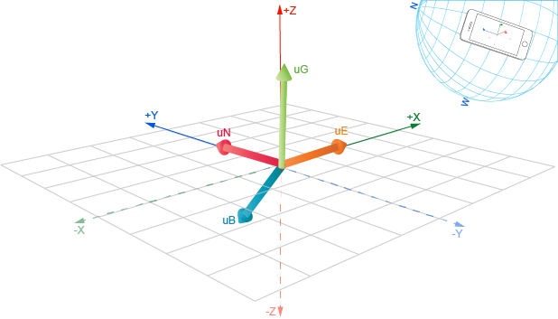
By taking the cross product between the the magnetic field vector and gravity vector (see Gravity Sensor), we get a vector which points East on the ground plane, using the right hand rule.
Now if we take the cross product between the gravity vector and the newly found East vector, the resulting vector will point in the northern direction towards the Earth’s magnetic field.
The illustration below represents the case where the device is at rest and y-axis points towards the North. The reading from the Magnetometer is {x: 0, y: 11, z: -16} and Accelerometer reports {x: 0.11, y: 0.07, z: 9.81} acceleration. The uG is a unit vector representing the gravity, uB represents magnetic field vector, uE = uB × uG and points East. The uN = uG × uE points to the northern direction.
That means an Absolute Orientation Sensor is a fusion sensor of the Magnetometer and the Accelerometer, and potentially the Gyroscope for better isolated gravity (see Gravity Sensor).
4.4. Geomagnetic Orientation Sensor
A Geomagnetic Orientation Sensor, is like a Absolute Orientation Sensor, but doesn’t use the Gyroscope which means it uses less power. This also means that it is more sensitive to shakes and movement.
As the main use-case for a Geomagnetic Orientation Sensor is to create a compass, or use compass direction within a mapping application, this is not much of a problem since people usually hold the device steady for these use-cases.
The actual heading (N, S, E, W) can be found by adjusting the rotation vector with the local declination compensation calculated from the current geolocation position.
As the sensor uses the accelerometer to get a more steady heading, like when walking, the rotation vector is projected to the plane perpendicular to the gravity vector (as isolated from the accelerometer) which more or less represents the ground plane. This also means that if you are interested in the actual orientation of the gravity vector, then use the magnetometer directly instead.
4.5. Relative Orientation Sensor
On most sensor hubs, gravity is isolated from the accelerometer using the gyroscope, and the linear acceleration is isolated by removing the isolated gravity, from the accelerometer values.
This avoids the delay which low and high pass filters introduce.
One way of doing this is using a Kalman filter or complementary filter, which leads us to the Relative Orientation Sensor. As a complementary filter yields quite good results and is easy to implement in hardware, this is a common solution.
4.5.1. Complementary filter
A complementary filter can be thought of as a low-pass filter and high-pass filter in one, complementing the gyroscope values with the accelerometer values:
θn = α × (θn-1 + ω × ∂t) + (1.0 - α) × a
With α being the weight constant, a the acceleration from accelerometer, ω the angular velocity from gyroscope and ∂t being the time between measurements.
A common value for α is 0.98, which means that 98% of the weight lays on the gyroscope measurements.
The gyroscope measures angular velocity, so by multiplying with the time difference, we get the change of angle. This change is always calculated relative to the current device position, so we need to use the accelerometer, which includes gravity, to calibrate this to the ground plane.
The values from the accelerometer bring no information about the heading (alpha, the rotation around z), so we don’t include that in our alpha component. On the other hand, the accelerometer (due to gravity) provides information on how the device is held around the x and y axis (beta and gamma).
When there is no or little movement, the vector obtained from the accelerometer reading will contribute more to the (alpha, beta, gamma) angles than the gyroscope.
As values from a steady accelerometer represent the gravity vector, and we don’t include the z component in the alpha, the result of this is that the orientation will just follow the gyroscope and be stable. But as the origin of the heading depends on the device position at start this a device-relative orientation sensor.
const options = { frequency: 50 };

const accl = new Accelerometer(options);
const gyro = new Gyroscope(options);

let timestamp = null;
let alpha = beta = gamma = 0;
const bias = 0.98;

gyro.onreading = () => {
   let dt = timestamp ? (gyro.timestamp - timestamp) / 1000 : 0;
   timestamp = gyro.timestamp;

   // Treat the acceleration vector as an orientation vector by normalizing it.
   // Keep in mind that the if the device is flipped, the vector will just be
   // pointing in the other direction, so we have no way to know from the
   // accelerometer data which way the device is oriented.
   const norm = Math.sqrt(accl.x ** 2 + accl.y ** 2 + accl.z ** 2);

   // As we only can cover half (PI rad) of the full spectrum (2*PI rad) we multiply
   // the unit vector with values from [-1, 1] with PI/2, covering [-PI/2, PI/2].
   const scale = Math.PI / 2;

   alpha = alpha + gyro.z * dt;
   beta = bias * (beta + gyro.x * dt) + (1.0 - bias) * (accl.x * scale / norm);
   gamma = bias * (gamma + gyro.y * dt) + (1.0 - bias) * (accl.y * -scale / norm);

   // Do something with Euler angles (alpha, beta, gamma).
 };

 accl.start();
 gyro.start();
From the above example, we notice that the alpha represented the initial heading orientation. We also know that this heading might drift over time due to being based on the gyroscope.
In some situations you might want the orientation to drift towards your current position. This can be useful for a controller inside a virtual reality environment, where you want a car to follow the heading of your controller, but you might move and turn around while playing. That would more or less work like driving a real car.
Changing one line in the above accomplishes that.
const zeroBias = 0.02;
alpha = (1 - zeroBias) * (alpha + gyro.z * dt);
With the above 2% of the alpha consists of the value 0. Thus, when the device is being held more or less steady, the heading will move towards 0, meaning being adjusted to your current device position and not positioned according to the surroundings.
This example shows how useful manual fusion can be at times.
4.6. Gravity and Linear Acceleration Sensor
The complementary filter used above is quite good at isolating the gravity, and most sensor hubs thus isolate gravity from the accelerometer using the gyroscope, and the linear acceleration is isolated by removing the isolated gravity, from the accelerometer values.
This also means that the Linear Acceleration Sensor and the Gravity Sensor as exposed by most sensor hubs are most likely fusion sensors.
Gravity can also be removed from a linear acceleration sensor using a magnetometer, as the magnetic field vector is more or less stable.
The LinearAccelerationSensor interface and GravitySensor interface are defined in [ACCELEROMETER] specification.
Note, as the gravity changes with the frequency of the movements, i.e., 0 in falling direction in free fall, you can imagine that linear acceleration will be quite imprecise if you are trying to detect a shake, so keep that in mind.
4.7. Use Cases and Requirements
Advanced motion sensor use-cases could have requirements for accurate sensor readings, high sampling rates at which hardware sensor operates, and reading delivery rate that is preferable for particular application.
Motion sensors can be used for variety of advanced use-cases, such as:
-
Virtual and augmented reality HMD tracking [HMDTRACKING]
-
Sensor assisted indoor mapping and navigation [INDOORNAV], [IPIN]
-
Photo and video capture stabilization [ROLLSTABILIZER], [VIDEOSTABILIZER]
-
Games that require high-frequency sampling rates with high accuracy readings.
-
3D scanning [3DSCANNING]
-
Advanced gesture recognition [MEMSGESTURES]
-
Step counting and monitoring of other physical activities [PHYSMON]
The generic requirement for games or UI applications that use motion sensors is to have a new sensor reading per rendered frame. The higher sampling rates in this case, will reduce latency, thus improve user experience.
In case of virtual reality HMD tracking, sensors might run at very high sampling rates (up to several kHz) and minimize motion-to-photon latency by providing latest sensor reading for every rendered frame at refresh rates of 75-120Hz.
Indoor navigation or non-realtime video (image) stabilization applications could benefit from collecting high accuracy sensor readings at high sampling rates (80-100Hz), so that data processing algorithms have enough samples to provide accurate results.