Chapter 9: Basic Shapes
Contents
9.1. Introduction and definitions
- basic shape
- shape
- shape elements
- A graphics element that is defined by some combination of
straight lines and curves. Specifically:
‘circle’, ‘ellipse’, ‘line’, ‘path’, ‘polygon’, ‘polyline’ and ‘rect’.
SVG contains the following set of basic shape elements:
- rectangles (including optional rounded corners), created with the ‘rect’ element,
- circles, created with the ‘circle’ element,
- ellipses, created with the ‘ellipse’ element,
- straight lines, created with the ‘line’ element,
- polylines, created with the ‘polyline’ element, and
- polygons, created with the ‘polygon’ element.
Mathematically, these shape elements are equivalent to a
‘path’ element that would construct the same shape. The basic
shapes may be stroked, filled and used as clip paths. All of the
properties available for ‘path’ elements also apply to the basic
shapes.
The equivalent path and algorithm to compute the stroke for each shape
are defined in the shape sections below.
9.2. The ‘rect’ element
The ‘rect’ element defines a rectangle which is axis-aligned
with the current local coordinate system. Rounded rectangles can be achieved by setting
appropriate values for attributes ‘rx’ and ‘ry’.
‘rect’
- Categories:
- Graphics element, shape element
- Content model:
- Any number of the following elements, in any order:
- animation elements — ‘animate’, ‘animateMotion’, ‘animateTransform’, ‘discard’, ‘set’
- descriptive elements — ‘desc’, ‘title’, ‘metadata’
- paint server elements — ‘solidcolor’, ‘linearGradient’, ‘radialGradient’, ‘mesh’, ‘pattern’, ‘hatch’
clipPath, marker, mask, script - Attributes:
- aria attributes — ‘aria-activedescendant’, ‘aria-atomic’, ‘aria-autocomplete’, ‘aria-busy’, ‘aria-checked’, ‘aria-colcount’, ‘aria-colindex’, ‘aria-colspan’, ‘aria-controls’, ‘aria-current’, ‘aria-describedat’, ‘aria-describedby’, ‘aria-disabled’, ‘aria-dropeffect’, ‘aria-expanded’, ‘aria-flowto’, ‘aria-grabbed’, ‘aria-haspopup’, ‘aria-hidden’, ‘aria-invalid’, ‘aria-label’, ‘aria-labelledby’, ‘aria-level’, ‘aria-live’, ‘aria-modal’, ‘aria-multiline’, ‘aria-multiselectable’, ‘aria-orientation’, ‘aria-owns’, ‘aria-placeholder’, ‘aria-posinset’, ‘aria-pressed’, ‘aria-readonly’, ‘aria-relevant’, ‘aria-required’, ‘aria-rowcount’, ‘aria-rowindex’, ‘aria-rowspan’, ‘aria-selected’, ‘aria-setsize’, ‘aria-sort’, ‘aria-valuemax’, ‘aria-valuemin’, ‘aria-valuenow’, ‘aria-valuetext’, ‘role’
- conditional processing attributes — ‘requiredExtensions’, ‘systemLanguage’
- core attributes — ‘id’, ‘tabindex’, ‘lang’, ‘xml:space’
- global event attributes — ‘oncancel’, ‘oncanplay’, ‘oncanplaythrough’, ‘onchange’, ‘onclick’, ‘onclose’, ‘oncuechange’, ‘ondblclick’, ‘ondrag’, ‘ondragend’, ‘ondragenter’, ‘ondragexit’, ‘ondragleave’, ‘ondragover’, ‘ondragstart’, ‘ondrop’, ‘ondurationchange’, ‘onemptied’, ‘onended’, ‘onerror’, ‘onfocus’, ‘oninput’, ‘oninvalid’, ‘onkeydown’, ‘onkeypress’, ‘onkeyup’, ‘onload’, ‘onloadeddata’, ‘onloadedmetadata’, ‘onloadstart’, ‘onmousedown’, ‘onmouseenter’, ‘onmouseleave’, ‘onmousemove’, ‘onmouseout’, ‘onmouseover’, ‘onmouseup’, ‘onmousewheel’, ‘onpause’, ‘onplay’, ‘onplaying’, ‘onprogress’, ‘onratechange’, ‘onreset’, ‘onresize’, ‘onscroll’, ‘onseeked’, ‘onseeking’, ‘onselect’, ‘onshow’, ‘onstalled’, ‘onsubmit’, ‘onsuspend’, ‘ontimeupdate’, ‘ontoggle’, ‘onvolumechange’, ‘onwaiting’
- graphical event attributes — ‘onfocusin’, ‘onfocusout’
- presentation attributes —
- style attributes — ‘class’, ‘style’
- Geometry properties:
- DOM Interfaces:
The ‘x’ and ‘y’ coordinates refer to the left and top edges of the rectangle,
in the current user coordinate system.
The ‘width’ and ‘height’ of the rectangle. A negative value for either
attribute is an error (see Error processing).
A value of zero for either attribute disables rendering of the element.
For rounded rectangles, the x- and y-axis radii of the
ellipse used to round off the corners of the rectangle.
A negative value for either attribute is an error
(see Error processing).
The values used for the x- and y-axis rounded corner radii are
determined implicitly if the ‘rx’ or ‘ry’ attributes (or both)
are not specified, or are specified but with invalid values.
The values are also subject to clamping so that the lengths of
the straight segments of the rectangle are never negative. The
effective values for ‘rx’ and ‘ry’ are determined by following
these steps in order:
- Let rx and ry be length values.
- If neither ‘
rx’ nor ‘ry’ are properly specified, then set both
rx and ry to 0. (This will result in square corners.)
- Otherwise, if a properly specified value is provided for ‘
rx’, but
not for ‘ry’, then set both rx and ry to the value of ‘rx’.
- Otherwise, if a properly specified value is provided for ‘
ry’, but
not for ‘rx’, then set both rx and ry to the value of ‘ry’.
- Otherwise, both ‘
rx’ and ‘ry’ were specified properly. Set rx to
the value of ‘rx’ and ry to the value of ‘ry’.
- If rx is greater than half of ‘
width’, then set
rx to half of ‘width’.
- If ry is greater than half of ‘
height’, then set
ry to half of ‘height’.
- The effective values of ‘
rx’ and ‘ry’ are rx and
ry, respectively.
Mathematically, a ‘rect’ element is mapped to an
equivalent ‘path’ element as follows: (Note: all coordinate and
length values are first converted into local coordinate system coordinates according
to Units.)
- perform an absolute moveto operation to
location (x+rx,y), where x is the value of
the ‘rect’ element's ‘
x’ attribute converted to user
space, rx is the effective value of the ‘rx’ attribute
converted to local coordinate system and y is the value of the ‘y’
attribute converted to local coordinate system
- perform an absolute horizontal lineto
operation to location (x+width-rx,y), where width
is the ‘rect’ element's ‘
width’ attribute converted to user
space
- perform an absolute elliptical arc
operation to coordinate (x+width,y+ry), where the effective
values for the ‘
rx’ and ‘ry’ attributes on the ‘rect’
element converted to local coordinate system are used as the rx and ry
attributes on the elliptical arc
command, respectively, the x-axis-rotation is set to zero, the
large-arc-flag is set to zero, and the sweep-flag is set
to one
- perform a absolute vertical lineto to location
(x+width,y+height-ry), where height is the
‘rect’ element's ‘
height’ attribute converted to user
space
- perform an absolute elliptical arc
operation to coordinate (x+width-rx,y+height)
- perform an absolute horizontal lineto to location
(x+rx,y+height)
- perform an absolute elliptical arc
operation to coordinate (x,y+height-ry)
- perform an absolute absolute vertical lineto to location
(x,y+ry)
- perform an absolute elliptical arc
operation to coordinate (x+rx,y)
Path decomposition resolved during teleconference on
June
3rd, 2013.
Example rect01 shows a
rectangle with sharp corners. The ‘rect’ element is filled with yellow
and stroked with navy.
<?xml version="1.0" standalone="no"?>
<svg width="12cm" height="4cm" viewBox="0 0 1200 400"
     xmlns="http://www.w3.org/2000/svg" version="1.1">
  <desc>Example rect01 - rectangle with sharp corners</desc>

  <!-- Show outline of canvas using 'rect' element -->
  <rect x="1" y="1" width="1198" height="398"
        fill="none" stroke="blue" stroke-width="2"/>

  <rect x="400" y="100" width="400" height="200"
        fill="yellow" stroke="navy" stroke-width="10"  />
</svg>View this example as SVG (SVG-enabled browsers only)
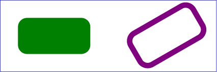
Example rect02 shows
two rounded rectangles. The ‘rx’ specifies how to round the corners of
the rectangles. Note that since no value has been specified for the ‘ry’
attribute, it will be assigned the same value as the ‘rx’ attribute.
<?xml version="1.0" standalone="no"?>
<svg width="12cm" height="4cm" viewBox="0 0 1200 400"
     xmlns="http://www.w3.org/2000/svg" version="1.1">
  <desc>Example rect02 - rounded rectangles</desc>

  <!-- Show outline of canvas using 'rect' element -->
  <rect x="1" y="1" width="1198" height="398"
        fill="none" stroke="blue" stroke-width="2"/>

  <rect x="100" y="100" width="400" height="200" rx="50"
        fill="green" />

  <g transform="translate(700 210) rotate(-30)">
    <rect x="0" y="0" width="400" height="200" rx="50"
          fill="none" stroke="purple" stroke-width="30" />
  </g>
</svg>View this example as SVG (SVG-enabled browsers only)
9.3. The ‘circle’ element
The ‘circle’ element defines a circle based on a center point and a
radius.
‘circle’
- Categories:
- Graphics element, shape element
- Content model:
- Any number of the following elements, in any order:
- animation elements — ‘animate’, ‘animateMotion’, ‘animateTransform’, ‘discard’, ‘set’
- descriptive elements — ‘desc’, ‘title’, ‘metadata’
- paint server elements — ‘solidcolor’, ‘linearGradient’, ‘radialGradient’, ‘mesh’, ‘pattern’, ‘hatch’
clipPath, marker, mask, script - Attributes:
- aria attributes — ‘aria-activedescendant’, ‘aria-atomic’, ‘aria-autocomplete’, ‘aria-busy’, ‘aria-checked’, ‘aria-colcount’, ‘aria-colindex’, ‘aria-colspan’, ‘aria-controls’, ‘aria-current’, ‘aria-describedat’, ‘aria-describedby’, ‘aria-disabled’, ‘aria-dropeffect’, ‘aria-expanded’, ‘aria-flowto’, ‘aria-grabbed’, ‘aria-haspopup’, ‘aria-hidden’, ‘aria-invalid’, ‘aria-label’, ‘aria-labelledby’, ‘aria-level’, ‘aria-live’, ‘aria-modal’, ‘aria-multiline’, ‘aria-multiselectable’, ‘aria-orientation’, ‘aria-owns’, ‘aria-placeholder’, ‘aria-posinset’, ‘aria-pressed’, ‘aria-readonly’, ‘aria-relevant’, ‘aria-required’, ‘aria-rowcount’, ‘aria-rowindex’, ‘aria-rowspan’, ‘aria-selected’, ‘aria-setsize’, ‘aria-sort’, ‘aria-valuemax’, ‘aria-valuemin’, ‘aria-valuenow’, ‘aria-valuetext’, ‘role’
- conditional processing attributes — ‘requiredExtensions’, ‘systemLanguage’
- core attributes — ‘id’, ‘tabindex’, ‘lang’, ‘xml:space’
- global event attributes — ‘oncancel’, ‘oncanplay’, ‘oncanplaythrough’, ‘onchange’, ‘onclick’, ‘onclose’, ‘oncuechange’, ‘ondblclick’, ‘ondrag’, ‘ondragend’, ‘ondragenter’, ‘ondragexit’, ‘ondragleave’, ‘ondragover’, ‘ondragstart’, ‘ondrop’, ‘ondurationchange’, ‘onemptied’, ‘onended’, ‘onerror’, ‘onfocus’, ‘oninput’, ‘oninvalid’, ‘onkeydown’, ‘onkeypress’, ‘onkeyup’, ‘onload’, ‘onloadeddata’, ‘onloadedmetadata’, ‘onloadstart’, ‘onmousedown’, ‘onmouseenter’, ‘onmouseleave’, ‘onmousemove’, ‘onmouseout’, ‘onmouseover’, ‘onmouseup’, ‘onmousewheel’, ‘onpause’, ‘onplay’, ‘onplaying’, ‘onprogress’, ‘onratechange’, ‘onreset’, ‘onresize’, ‘onscroll’, ‘onseeked’, ‘onseeking’, ‘onselect’, ‘onshow’, ‘onstalled’, ‘onsubmit’, ‘onsuspend’, ‘ontimeupdate’, ‘ontoggle’, ‘onvolumechange’, ‘onwaiting’
- graphical event attributes — ‘onfocusin’, ‘onfocusout’
- presentation attributes —
- style attributes — ‘class’, ‘style’
- Geometry properties:
- DOM Interfaces:
The ‘cx’ and ‘cy’ attributes define the coordinates of the center of the circle.
The ‘r’ attribute defines the radius of the circle. A negative value
is an error (see Error processing).
A value of zero disables rendering of the element.
Mathematically, a ‘circle’ element is mapped to an
equivalent ‘path’ element that consists of four
elliptical
arc segments, each covering a quarter of the circle. The path
begins at the "3 o'clock" point on the radius and proceeds in a
clock-wise direction (before any transformations).
Path decomposition resolved during teleconference on
June
3rd, 2013.
Example
circle01 consists of a ‘circle’ element that is filled
with red and stroked with blue.
<?xml version="1.0" standalone="no"?>
<svg width="12cm" height="4cm" viewBox="0 0 1200 400"
     xmlns="http://www.w3.org/2000/svg" version="1.1">
  <desc>Example circle01 - circle filled with red and stroked with blue</desc>

  <!-- Show outline of canvas using 'rect' element -->
  <rect x="1" y="1" width="1198" height="398"
        fill="none" stroke="blue" stroke-width="2"/>

  <circle cx="600" cy="200" r="100"
        fill="red" stroke="blue" stroke-width="10"  />
</svg>View this example as SVG (SVG-enabled browsers only)
9.4. The ‘ellipse’ element
The ‘ellipse’ element defines an ellipse which is axis-aligned
with the current local coordinate system based on a center point and two radii.
‘ellipse’
- Categories:
- Graphics element, shape element
- Content model:
- Any number of the following elements, in any order:
- animation elements — ‘animate’, ‘animateMotion’, ‘animateTransform’, ‘discard’, ‘set’
- descriptive elements — ‘desc’, ‘title’, ‘metadata’
- paint server elements — ‘solidcolor’, ‘linearGradient’, ‘radialGradient’, ‘mesh’, ‘pattern’, ‘hatch’
clipPath, marker, mask, script - Attributes:
- aria attributes — ‘aria-activedescendant’, ‘aria-atomic’, ‘aria-autocomplete’, ‘aria-busy’, ‘aria-checked’, ‘aria-colcount’, ‘aria-colindex’, ‘aria-colspan’, ‘aria-controls’, ‘aria-current’, ‘aria-describedat’, ‘aria-describedby’, ‘aria-disabled’, ‘aria-dropeffect’, ‘aria-expanded’, ‘aria-flowto’, ‘aria-grabbed’, ‘aria-haspopup’, ‘aria-hidden’, ‘aria-invalid’, ‘aria-label’, ‘aria-labelledby’, ‘aria-level’, ‘aria-live’, ‘aria-modal’, ‘aria-multiline’, ‘aria-multiselectable’, ‘aria-orientation’, ‘aria-owns’, ‘aria-placeholder’, ‘aria-posinset’, ‘aria-pressed’, ‘aria-readonly’, ‘aria-relevant’, ‘aria-required’, ‘aria-rowcount’, ‘aria-rowindex’, ‘aria-rowspan’, ‘aria-selected’, ‘aria-setsize’, ‘aria-sort’, ‘aria-valuemax’, ‘aria-valuemin’, ‘aria-valuenow’, ‘aria-valuetext’, ‘role’
- conditional processing attributes — ‘requiredExtensions’, ‘systemLanguage’
- core attributes — ‘id’, ‘tabindex’, ‘lang’, ‘xml:space’
- global event attributes — ‘oncancel’, ‘oncanplay’, ‘oncanplaythrough’, ‘onchange’, ‘onclick’, ‘onclose’, ‘oncuechange’, ‘ondblclick’, ‘ondrag’, ‘ondragend’, ‘ondragenter’, ‘ondragexit’, ‘ondragleave’, ‘ondragover’, ‘ondragstart’, ‘ondrop’, ‘ondurationchange’, ‘onemptied’, ‘onended’, ‘onerror’, ‘onfocus’, ‘oninput’, ‘oninvalid’, ‘onkeydown’, ‘onkeypress’, ‘onkeyup’, ‘onload’, ‘onloadeddata’, ‘onloadedmetadata’, ‘onloadstart’, ‘onmousedown’, ‘onmouseenter’, ‘onmouseleave’, ‘onmousemove’, ‘onmouseout’, ‘onmouseover’, ‘onmouseup’, ‘onmousewheel’, ‘onpause’, ‘onplay’, ‘onplaying’, ‘onprogress’, ‘onratechange’, ‘onreset’, ‘onresize’, ‘onscroll’, ‘onseeked’, ‘onseeking’, ‘onselect’, ‘onshow’, ‘onstalled’, ‘onsubmit’, ‘onsuspend’, ‘ontimeupdate’, ‘ontoggle’, ‘onvolumechange’, ‘onwaiting’
- graphical event attributes — ‘onfocusin’, ‘onfocusout’
- presentation attributes —
- style attributes — ‘class’, ‘style’
- Geometry properties:
- DOM Interfaces:
The ‘cx’ and ‘cy’ coordinates define the center of the ellipse.
The ‘cx’ and ‘cy’ attributes define the x- and y-axis radii of the
ellipse. A negative value for either attribute is an error (see
Error processing).
A value of zero disables rendering of the element.
Mathematically, an ‘ellipse’ element is mapped to an
equivalent ‘path’ element that consists of four
elliptical
arc segments, each covering a quarter of the ellipse. The path
begins at the "3 o'clock" point on the radius and proceeds in a
clock-wise direction (before any transformation).
Path decomposition resolved during teleconference on
June
3rd, 2013.
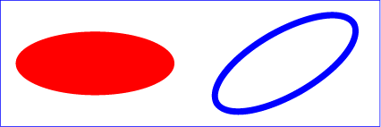
Example ellipse01 below specifies
the coordinates of the two ellipses in the user coordinate system
established by the ‘viewBox’ attribute on the ‘svg’
element and the ‘transform’ property on the ‘g’ and
‘ellipse’ elements. Both ellipses use the default values of
zero for the ‘cx’ and ‘cy’ attributes (the center of the
ellipse). The second ellipse is rotated.
<?xml version="1.0" standalone="no"?>
<svg width="12cm" height="4cm" viewBox="0 0 1200 400"
     xmlns="http://www.w3.org/2000/svg" version="1.1">
  <desc>Example ellipse01 - examples of ellipses</desc>

  <!-- Show outline of canvas using 'rect' element -->
  <rect x="1" y="1" width="1198" height="398"
        fill="none" stroke="blue" stroke-width="2" />

  <g transform="translate(300 200)">
    <ellipse rx="250" ry="100"
          fill="red"  />
  </g>

  <ellipse transform="translate(900 200) rotate(-30)"
        rx="250" ry="100"
        fill="none" stroke="blue" stroke-width="20"  />

</svg>View this example as SVG (SVG-enabled browsers only)
9.5. The ‘line’ element
The ‘line’ element defines a line segment that starts at one point
and ends at another.
‘line’
- Categories:
- Graphics element, markable element, shape element
- Content model:
- Any number of the following elements, in any order:
- animation elements — ‘animate’, ‘animateMotion’, ‘animateTransform’, ‘discard’, ‘set’
- descriptive elements — ‘desc’, ‘title’, ‘metadata’
- paint server elements — ‘solidcolor’, ‘linearGradient’, ‘radialGradient’, ‘mesh’, ‘pattern’, ‘hatch’
clipPath, marker, mask, script - Attributes:
- aria attributes — ‘aria-activedescendant’, ‘aria-atomic’, ‘aria-autocomplete’, ‘aria-busy’, ‘aria-checked’, ‘aria-colcount’, ‘aria-colindex’, ‘aria-colspan’, ‘aria-controls’, ‘aria-current’, ‘aria-describedat’, ‘aria-describedby’, ‘aria-disabled’, ‘aria-dropeffect’, ‘aria-expanded’, ‘aria-flowto’, ‘aria-grabbed’, ‘aria-haspopup’, ‘aria-hidden’, ‘aria-invalid’, ‘aria-label’, ‘aria-labelledby’, ‘aria-level’, ‘aria-live’, ‘aria-modal’, ‘aria-multiline’, ‘aria-multiselectable’, ‘aria-orientation’, ‘aria-owns’, ‘aria-placeholder’, ‘aria-posinset’, ‘aria-pressed’, ‘aria-readonly’, ‘aria-relevant’, ‘aria-required’, ‘aria-rowcount’, ‘aria-rowindex’, ‘aria-rowspan’, ‘aria-selected’, ‘aria-setsize’, ‘aria-sort’, ‘aria-valuemax’, ‘aria-valuemin’, ‘aria-valuenow’, ‘aria-valuetext’, ‘role’
- conditional processing attributes — ‘requiredExtensions’, ‘systemLanguage’
- core attributes — ‘id’, ‘tabindex’, ‘lang’, ‘xml:space’
- global event attributes — ‘oncancel’, ‘oncanplay’, ‘oncanplaythrough’, ‘onchange’, ‘onclick’, ‘onclose’, ‘oncuechange’, ‘ondblclick’, ‘ondrag’, ‘ondragend’, ‘ondragenter’, ‘ondragexit’, ‘ondragleave’, ‘ondragover’, ‘ondragstart’, ‘ondrop’, ‘ondurationchange’, ‘onemptied’, ‘onended’, ‘onerror’, ‘onfocus’, ‘oninput’, ‘oninvalid’, ‘onkeydown’, ‘onkeypress’, ‘onkeyup’, ‘onload’, ‘onloadeddata’, ‘onloadedmetadata’, ‘onloadstart’, ‘onmousedown’, ‘onmouseenter’, ‘onmouseleave’, ‘onmousemove’, ‘onmouseout’, ‘onmouseover’, ‘onmouseup’, ‘onmousewheel’, ‘onpause’, ‘onplay’, ‘onplaying’, ‘onprogress’, ‘onratechange’, ‘onreset’, ‘onresize’, ‘onscroll’, ‘onseeked’, ‘onseeking’, ‘onselect’, ‘onshow’, ‘onstalled’, ‘onsubmit’, ‘onsuspend’, ‘ontimeupdate’, ‘ontoggle’, ‘onvolumechange’, ‘onwaiting’
- graphical event attributes — ‘onfocusin’, ‘onfocusout’
- presentation attributes —
- style attributes — ‘class’, ‘style’
- ‘x1’
- ‘y1’
- ‘x2’
- ‘y2’
- DOM Interfaces:
Attribute definitions:
-
-
The x- and y-axis coordinates of the start of the line.
-
-
The x- and y-axis coordinates of the end of the line.
Mathematically, a ‘line’ element can be mapped to an
equivalent ‘path’ element as follows: (Note: all coordinate and
length values are first converted into local coordinate system coordinates according
to Units.)
- perform an absolute moveto
operation to absolute location (x1,y1), where x1
and y1 are the values of the ‘line’ element's ‘x1’ and
‘y1’ attributes converted to local coordinate system, respectively
- perform an absolute lineto
operation to absolute location (x2,y2), where x2
and y2 are the values of the ‘line’ element's ‘x2’ and
‘y2’ attributes converted to local coordinate system, respectively
Because ‘line’ elements are single lines and thus are geometrically
one-dimensional, they have no interior; thus, ‘line’ elements are never
filled (see the ‘fill’ property).
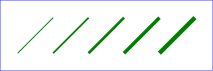
Example line01 below
specifies the coordinates of the five lines in the user coordinate system
established by the ‘viewBox’ attribute on the ‘svg’ element. The
lines have different thicknesses.
<?xml version="1.0" standalone="no"?>
<svg width="12cm" height="4cm" viewBox="0 0 1200 400"
     xmlns="http://www.w3.org/2000/svg" version="1.1">
  <desc>Example line01 - lines expressed in user coordinates</desc>

  <!-- Show outline of canvas using 'rect' element -->
  <rect x="1" y="1" width="1198" height="398"
        fill="none" stroke="blue" stroke-width="2" />

  <g stroke="green" >
    <line x1="100" y1="300" x2="300" y2="100"
            stroke-width="5"  />
    <line x1="300" y1="300" x2="500" y2="100"
            stroke-width="10"  />
    <line x1="500" y1="300" x2="700" y2="100"
            stroke-width="15"  />
    <line x1="700" y1="300" x2="900" y2="100"
            stroke-width="20"  />
    <line x1="900" y1="300" x2="1100" y2="100"
            stroke-width="25"  />
  </g>
</svg>View this example as SVG (SVG-enabled browsers only)
9.6. The ‘polyline’ element
The ‘polyline’ element defines a set of connected straight
line segments. Typically, ‘polyline’ elements define open
shapes.
‘polyline’
- Categories:
- Graphics element, markable element, shape element
- Content model:
- Any number of the following elements, in any order:
- animation elements — ‘animate’, ‘animateMotion’, ‘animateTransform’, ‘discard’, ‘set’
- descriptive elements — ‘desc’, ‘title’, ‘metadata’
- paint server elements — ‘solidcolor’, ‘linearGradient’, ‘radialGradient’, ‘mesh’, ‘pattern’, ‘hatch’
clipPath, marker, mask, script - Attributes:
- aria attributes — ‘aria-activedescendant’, ‘aria-atomic’, ‘aria-autocomplete’, ‘aria-busy’, ‘aria-checked’, ‘aria-colcount’, ‘aria-colindex’, ‘aria-colspan’, ‘aria-controls’, ‘aria-current’, ‘aria-describedat’, ‘aria-describedby’, ‘aria-disabled’, ‘aria-dropeffect’, ‘aria-expanded’, ‘aria-flowto’, ‘aria-grabbed’, ‘aria-haspopup’, ‘aria-hidden’, ‘aria-invalid’, ‘aria-label’, ‘aria-labelledby’, ‘aria-level’, ‘aria-live’, ‘aria-modal’, ‘aria-multiline’, ‘aria-multiselectable’, ‘aria-orientation’, ‘aria-owns’, ‘aria-placeholder’, ‘aria-posinset’, ‘aria-pressed’, ‘aria-readonly’, ‘aria-relevant’, ‘aria-required’, ‘aria-rowcount’, ‘aria-rowindex’, ‘aria-rowspan’, ‘aria-selected’, ‘aria-setsize’, ‘aria-sort’, ‘aria-valuemax’, ‘aria-valuemin’, ‘aria-valuenow’, ‘aria-valuetext’, ‘role’
- conditional processing attributes — ‘requiredExtensions’, ‘systemLanguage’
- core attributes — ‘id’, ‘tabindex’, ‘lang’, ‘xml:space’
- global event attributes — ‘oncancel’, ‘oncanplay’, ‘oncanplaythrough’, ‘onchange’, ‘onclick’, ‘onclose’, ‘oncuechange’, ‘ondblclick’, ‘ondrag’, ‘ondragend’, ‘ondragenter’, ‘ondragexit’, ‘ondragleave’, ‘ondragover’, ‘ondragstart’, ‘ondrop’, ‘ondurationchange’, ‘onemptied’, ‘onended’, ‘onerror’, ‘onfocus’, ‘oninput’, ‘oninvalid’, ‘onkeydown’, ‘onkeypress’, ‘onkeyup’, ‘onload’, ‘onloadeddata’, ‘onloadedmetadata’, ‘onloadstart’, ‘onmousedown’, ‘onmouseenter’, ‘onmouseleave’, ‘onmousemove’, ‘onmouseout’, ‘onmouseover’, ‘onmouseup’, ‘onmousewheel’, ‘onpause’, ‘onplay’, ‘onplaying’, ‘onprogress’, ‘onratechange’, ‘onreset’, ‘onresize’, ‘onscroll’, ‘onseeked’, ‘onseeking’, ‘onselect’, ‘onshow’, ‘onstalled’, ‘onsubmit’, ‘onsuspend’, ‘ontimeupdate’, ‘ontoggle’, ‘onvolumechange’, ‘onwaiting’
- graphical event attributes — ‘onfocusin’, ‘onfocusout’
- presentation attributes —
- style attributes — ‘class’, ‘style’
- ‘points’
- DOM Interfaces:
Attribute definitions:
-
| Name |
Value |
Initial value |
Animatable |
| points |
<points> |
(none) |
yes |
-
where:
The points that make up the polyline. All coordinate
values are in the user coordinate system.
If an odd number of coordinates is provided, then the element is in
error, with the same user agent behavior as occurs with an incorrectly
specified ‘path’ element. In such error cases the user agent will drop
the last, odd coordinate and otherwise render the shape.
The initial value, (none), indicates that the polyline element
is valid but does not render.
Mathematically, a ‘polyline’ element can be mapped to an
equivalent ‘path’ element as follows:
- perform an absolute moveto
operation to the first coordinate pair in the list of points
- for each subsequent coordinate pair, perform an absolute
lineto operation to that
coordinate pair.
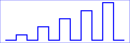
Example polyline01
below specifies a polyline in the user coordinate system established by the
‘viewBox’ attribute on the ‘svg’ element.
<?xml version="1.0" standalone="no"?>
<svg width="12cm" height="4cm" viewBox="0 0 1200 400"
     xmlns="http://www.w3.org/2000/svg" version="1.1">
  <desc>Example polyline01 - increasingly larger bars</desc>

  <!-- Show outline of canvas using 'rect' element -->
  <rect x="1" y="1" width="1198" height="398"
        fill="none" stroke="blue" stroke-width="2" />

  <polyline fill="none" stroke="blue" stroke-width="10"
            points="50,375
                    150,375 150,325 250,325 250,375
                    350,375 350,250 450,250 450,375
                    550,375 550,175 650,175 650,375
                    750,375 750,100 850,100 850,375
                    950,375 950,25 1050,25 1050,375
                    1150,375" />
</svg>View this example as SVG (SVG-enabled browsers only)
9.7. The ‘polygon’ element
The ‘polygon’ element defines a closed shape consisting of a
set of connected straight line segments.
‘polygon’
- Categories:
- Graphics element, markable element, shape element
- Content model:
- Any number of the following elements, in any order:
- animation elements — ‘animate’, ‘animateMotion’, ‘animateTransform’, ‘discard’, ‘set’
- descriptive elements — ‘desc’, ‘title’, ‘metadata’
- paint server elements — ‘solidcolor’, ‘linearGradient’, ‘radialGradient’, ‘mesh’, ‘pattern’, ‘hatch’
clipPath, marker, mask, script - Attributes:
- aria attributes — ‘aria-activedescendant’, ‘aria-atomic’, ‘aria-autocomplete’, ‘aria-busy’, ‘aria-checked’, ‘aria-colcount’, ‘aria-colindex’, ‘aria-colspan’, ‘aria-controls’, ‘aria-current’, ‘aria-describedat’, ‘aria-describedby’, ‘aria-disabled’, ‘aria-dropeffect’, ‘aria-expanded’, ‘aria-flowto’, ‘aria-grabbed’, ‘aria-haspopup’, ‘aria-hidden’, ‘aria-invalid’, ‘aria-label’, ‘aria-labelledby’, ‘aria-level’, ‘aria-live’, ‘aria-modal’, ‘aria-multiline’, ‘aria-multiselectable’, ‘aria-orientation’, ‘aria-owns’, ‘aria-placeholder’, ‘aria-posinset’, ‘aria-pressed’, ‘aria-readonly’, ‘aria-relevant’, ‘aria-required’, ‘aria-rowcount’, ‘aria-rowindex’, ‘aria-rowspan’, ‘aria-selected’, ‘aria-setsize’, ‘aria-sort’, ‘aria-valuemax’, ‘aria-valuemin’, ‘aria-valuenow’, ‘aria-valuetext’, ‘role’
- conditional processing attributes — ‘requiredExtensions’, ‘systemLanguage’
- core attributes — ‘id’, ‘tabindex’, ‘lang’, ‘xml:space’
- global event attributes — ‘oncancel’, ‘oncanplay’, ‘oncanplaythrough’, ‘onchange’, ‘onclick’, ‘onclose’, ‘oncuechange’, ‘ondblclick’, ‘ondrag’, ‘ondragend’, ‘ondragenter’, ‘ondragexit’, ‘ondragleave’, ‘ondragover’, ‘ondragstart’, ‘ondrop’, ‘ondurationchange’, ‘onemptied’, ‘onended’, ‘onerror’, ‘onfocus’, ‘oninput’, ‘oninvalid’, ‘onkeydown’, ‘onkeypress’, ‘onkeyup’, ‘onload’, ‘onloadeddata’, ‘onloadedmetadata’, ‘onloadstart’, ‘onmousedown’, ‘onmouseenter’, ‘onmouseleave’, ‘onmousemove’, ‘onmouseout’, ‘onmouseover’, ‘onmouseup’, ‘onmousewheel’, ‘onpause’, ‘onplay’, ‘onplaying’, ‘onprogress’, ‘onratechange’, ‘onreset’, ‘onresize’, ‘onscroll’, ‘onseeked’, ‘onseeking’, ‘onselect’, ‘onshow’, ‘onstalled’, ‘onsubmit’, ‘onsuspend’, ‘ontimeupdate’, ‘ontoggle’, ‘onvolumechange’, ‘onwaiting’
- graphical event attributes — ‘onfocusin’, ‘onfocusout’
- presentation attributes —
- style attributes — ‘class’, ‘style’
- ‘points’
- DOM Interfaces:
Attribute definitions:
-
| Name |
Value |
Initial value |
Animatable |
| points |
<points> |
(none) |
yes |
-
The points that make up the polygon. All coordinate
values are in the user coordinate system.
If an odd number of coordinates is provided, then the element is in
error, with the same user agent behavior as occurs with an incorrectly
specified ‘path’ element.
The initial value, (none), indicates that the polygon element
is valid, but does not render.
Mathematically, a ‘polygon’ element can be mapped to an
equivalent ‘path’ element as follows:
- perform an absolute moveto
operation to the first coordinate pair in the list of points
- for each subsequent coordinate pair, perform an absolute
lineto operation to that
coordinate pair
- perform a closepath
command
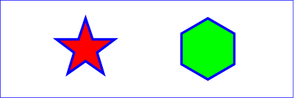
Example
polygon01 below specifies two polygons (a star and a hexagon) in
the user coordinate system established by the ‘viewBox’ attribute
on the ‘svg’ element.
<?xml version="1.0" standalone="no"?>
<svg width="12cm" height="4cm" viewBox="0 0 1200 400"
     xmlns="http://www.w3.org/2000/svg" version="1.1">
  <desc>Example polygon01 - star and hexagon</desc>

  <!-- Show outline of canvas using 'rect' element -->
  <rect x="1" y="1" width="1198" height="398"
        fill="none" stroke="blue" stroke-width="2" />

  <polygon fill="red" stroke="blue" stroke-width="10"
            points="350,75  379,161 469,161 397,215
                    423,301 350,250 277,301 303,215
                    231,161 321,161" />
  <polygon fill="lime" stroke="blue" stroke-width="10"
            points="850,75  958,137.5 958,262.5
                    850,325 742,262.6 742,137.5" />
</svg>View this example as SVG (SVG-enabled browsers only)
9.8. DOM interfaces
9.8.1. Interface SVGRectElement
An SVGRectElement object represents a ‘rect’ element in the DOM.
interface SVGRectElement : SVGGeometryElement {
  [SameObject] readonly attribute SVGAnimatedLength x;
  [SameObject] readonly attribute SVGAnimatedLength y;
  [SameObject] readonly attribute SVGAnimatedLength width;
  [SameObject] readonly attribute SVGAnimatedLength height;
  [SameObject] readonly attribute SVGAnimatedLength rx;
  [SameObject] readonly attribute SVGAnimatedLength ry;
};
The
x,
y,
width,
height,
rx and
ry IDL attributes
reflect the computed values of the ‘x’, ‘y’,
‘width’, ‘height’, ‘rx’ and ‘ry’
properties and their corresponding presentation attributes,
respectively.
9.8.2. Interface SVGCircleElement
An SVGCircleElement object represents a ‘circle’ element in the DOM.
interface SVGCircleElement : SVGGeometryElement {
  [SameObject] readonly attribute SVGAnimatedLength cx;
  [SameObject] readonly attribute SVGAnimatedLength cy;
  [SameObject] readonly attribute SVGAnimatedLength r;
};
The
cx,
cy and
r IDL attributes
reflect the computed values of the ‘cx’, ‘cy’
and ‘y’ properties and their corresponding presentation attributes,
respectively.
9.8.3. Interface SVGEllipseElement
An SVGEllipseElement object represents a ‘ellipse’ element in the DOM.
interface SVGEllipseElement : SVGGeometryElement {
  [SameObject] readonly attribute SVGAnimatedLength cx;
  [SameObject] readonly attribute SVGAnimatedLength cy;
  [SameObject] readonly attribute SVGAnimatedLength rx;
  [SameObject] readonly attribute SVGAnimatedLength ry;
};
The
cx,
cy,
rx and
ry
IDL attributes reflect the computed values of the
‘cx’, ‘cy’, ‘rx’ and ‘ry’ properties
and their corresponding presentation attributes,
respectively.
9.8.4. Interface SVGLineElement
The
SVGLineElement interface corresponds to the
‘line’
element.
interface SVGLineElement : SVGGeometryElement {
  [SameObject] readonly attribute SVGAnimatedLength x1;
  [SameObject] readonly attribute SVGAnimatedLength y1;
  [SameObject] readonly attribute SVGAnimatedLength x2;
  [SameObject] readonly attribute SVGAnimatedLength y2;
};
The
x1,
y1,
x2 and
y2 IDL attributes
reflect the ‘x1’, ‘y1’, ‘x2’ and ‘y2’
content attributes, respectively
9.8.5. Interface SVGAnimatedPoints
The SVGAnimatedPoints interface is used to reflect
a ‘points’ attribute on a ‘polygon’ or ‘polyline’
element. It is mixed in to the SVGPolygonElement and SVGPolylineElement
interfaces.
[NoInterfaceObject]
interface SVGAnimatedPoints {
  [SameObject] readonly attribute SVGPointList points;
  [SameObject] readonly attribute SVGPointList animatedPoints;
};
The points IDL attribute
represents the current non-animated value of the reflected attribute.
On getting points,
an SVGPointList object is returned that reflects the base
value of the reflected attribute.
The animatedPoints IDL attribute
represents the current non-animated value of the reflected attribute.
On getting animatedPoints,
an SVGPointList object is returned that reflects the animated
value of the reflected attribute.
The objects returned from points
and animatedPoints must be distinct, even
if there is no animation currently affecting the attribute.
9.8.6. Interface SVGPointList
The SVGPointList interface is a list interface whose
elements are DOMPoint objects. An SVGPointList
object represents a list of points.
interface SVGPointList {

  readonly attribute unsigned long length;
  readonly attribute unsigned long numberOfItems;

  void clear();
  DOMPoint initialize(DOMPoint newItem);
  getter DOMPoint getItem(unsigned long index);
  DOMPoint insertItemBefore(DOMPoint newItem, unsigned long index);
  DOMPoint replaceItem(DOMPoint newItem, unsigned long index);
  DOMPoint removeItem(unsigned long index);
  DOMPoint appendItem(DOMPoint newItem);
  setter void (unsigned long index, DOMPoint newItem);
};
The behavior of all of the interface members of SVGPointList are
defined in List interfaces.
This specification imposes additional requirements on the behaviour of DOMPoint
objects beyond those described in the
the Geometry Interfaces
specification, so that they can be used to reflect ‘points’ attributes.
Every DOMPoint object operates in one of four modes. It
can:
- reflect an element of the base value of a reflected animatable
attribute (being exposed through the methods on the
points member of
an SVGAnimatedPoints),
- reflect an element of the animated value of a reflected animatable
attribute (being exposed through the methods on the
animatedPoints member of
an SVGAnimatedPoints),
- represent the current translation of a given ‘svg’ element
(being exposed through the
currentTranslate
member on SVGSVGElement), or
- be detached, which is the case for DOMPoint objects created
using their constructor or with
createSVGPoint.
A DOMPoint object can be associated
with a particular element. The associated element is used to
determine which element's content attribute to update if the object reflects
an attribute. Unless otherwise described, a DOMPoint object is not
associated with any element.
A DOMPoint object can be designated as read only,
which means that attempts to modify the object will result in an exception
being thrown. When assigning to a read only DOMPoint's
x,
y,
w or
z
IDL attribute, a DOMException with code NO_MODIFICATION_ALLOWED_ERR must
be thrown instead of updating the internal coordinate value.
Note that this applies only to the read-write DOMPoint
interface; the DOMPointReadOnly interface, which is not used for reflecting
the ‘points’ attribute, will already throw an exception if
an attempt is made to modify it.
When assigning to a writable DOMPoint's
x,
y,
w or
z
IDL attribute, the following steps are run after updating
the internal coordinate value:
- If the DOMPoint reflects an element of the
base value of a reflected attribute, then reserialize
the reflected attribute using the SVGPointList that reflects
the attribute's base value.
The DOMPoint can't reflect an element of the
animated value, since it would be read only and we would have thrown
an exception per the requirements above.
- Otherwise, if the DOMPoint represents
the current translation of an ‘svg’ element and that
element is the outermost svg element, then:
- Let [a b c d e f]
be the 2x3 matrix that represents the document's magnification and panning
transform.
- Let x and y be the x and y coordinates of the
DOMPoint object, respectively.
- Set the document's magnification and panning transform to
[a 0 0 d x y].
9.8.7. Interface SVGPolylineElement
An SVGPolylineElement object represents a ‘polyline’ element in the DOM.
interface SVGPolylineElement : SVGGeometryElement {
};

SVGPolylineElement implements SVGAnimatedPoints;
9.8.8. Interface SVGPolygonElement
An SVGPolygonElement object represents a ‘polygon’ element in the DOM.
interface SVGPolygonElement : SVGGeometryElement {
};

SVGPolygonElement implements SVGAnimatedPoints;

