For all media, the canvas
describes "the space where the SVG content is rendered." The
canvas is infinite for each dimension of the space, but
rendering occurs relative to a finite rectangular region of the
canvas. This finite rectangular region is called the SVG viewport.
For visual media
([CSS21], section 7.3.1)
the SVG viewport is the viewing area where the user sees the SVG content.
The size of the SVG viewport (i.e., its width and height) is
determined by a negotiation process (see Establishing the size of the initial
viewport) between the SVG document fragment and its parent
(real or implicit). Once that negotiation process is completed,
the SVG user agent is provided the following information:
SVG content can be
embedded (by reference or inline) within a containing document. This containing
document might include attributes, properties and/or other
parameters (explicit or implicit) which specify or provide
hints about the dimensions of the viewport for the SVG content.
SVG content itself optionally can provide information about the
appropriate viewport region for the content via the ‘width’
and ‘height’ presentation attributes on the outermost svg element.
If SVG is embedded within a containing element.
Under these conditions, the positioning properties establish
the viewport's width.
The initial clipping path for the SVG document fragment is
established according to the rules described in The initial clipping
path.
If the SVG implementation is part of a user agent which
supports styling XML documents using CSS 2.1 compatible
px units, then the SVG user agent should get its
initial value for the size of a px unit in real world
units to match the value used for other XML styling operations;
otherwise, if the user agent can determine the size of a
px unit from its environment, it should use that
value; otherwise, it should choose an appropriate size for one
px unit. In all cases, the size of a px must
be in conformance with the rules described in CSS 2.1
([CSS21], section 4.3.2).
7.5. The ‘viewBox’ attribute
-
| Name |
Value |
Initial value |
Animatable |
| viewBox |
[<min-x> <min-y> <width> <height>] |
As if not specified. |
yes |
-
<min-x>, <min-x>, <width>, <height> = <number>
Transform on the ‘svg’ element is a bit special due to the ‘viewBox’ attribute. The transform should be applied as if the ‘svg’ had a parent element with that transform set.
RESOLUTION: transform property applies conceptually to the outside of the 'svg' element and there is no difference between
presentation attribute and style property (in terms of the visual result).
It is often desirable to specify that a given set of
graphics stretch to fit a particular container element. The
‘viewBox’ attribute provides this
capability.
All elements that establish a new viewport (see elements that
establish viewports), plus the
‘marker’,
‘pattern’ and
‘view’
elements have attribute
‘viewBox’. The value of the ‘viewBox’ attribute is a list of four
numbers <min-x>, <min-y>, <width> and <height>, separated by
whitespace and/or a comma, which specify a rectangle in user
space which should be mapped to the bounds of the viewport
established by the given element, taking into account attribute
‘preserveAspectRatio’. If specified,
an additional transformation is applied to all descendants of
the given element to achieve the specified effect.
A negative value for <width> or <height> is an error (see Error processing). A
value of zero disables rendering of the element.
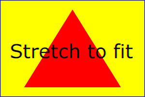
Example ViewBox illustrates
the use of the ‘viewBox’ attribute
on the outermost svg element to specify that
the SVG content should stretch to fit bounds of the
viewport.
<?xml version="1.0" standalone="no"?>
<svg width="300px" height="200px"
     viewBox="0 0 1500 1000" preserveAspectRatio="none"
     xmlns="http://www.w3.org/2000/svg">
  <desc>Example ViewBox - uses the viewBox
   attribute to automatically create an initial user coordinate
   system which causes the graphic to scale to fit into the
   viewport no matter what size the viewport is.</desc>
  <!-- This rectangle goes from (0,0) to (1500,1000) in local coordinate system.
       Because of the viewBox attribute above,
       the rectangle will end up filling the entire area
       reserved for the SVG content. -->
  <rect x="0" y="0" width="1500" height="1000"
        fill="yellow" stroke="blue" stroke-width="12"  />
  <!-- A large, red triangle -->
  <path fill="red"  d="M 750,100 L 250,900 L 1250,900 z"/>
  <!-- A text string that spans most of the viewport -->
  <text x="100" y="600" font-size="200" font-family="Verdana" >
    Stretch to fit
  </text>
</svg>
Example ViewBox
Rendered into
viewport with
width=300px,
height=200px |
|
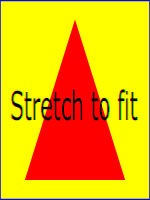
Rendered into
viewport with
width=150px,
height=200px |
 |
|
 |
View
this example as SVG (SVG-enabled browsers only)
The effect of the ‘viewBox’
attribute is that the user agent automatically supplies the
appropriate transformation matrix to map the specified
rectangle in local coordinate system to the bounds of a designated region
(often, the viewport). To achieve the effect of the example on
the left, with viewport dimensions of 300 by 200 pixels, the
user agent needs to automatically insert a transformation which
scales both X and Y by 0.2. The effect is equivalent to having
a viewport of size 300px by 200px and the following
supplemental transformation in the document, as follows:
<?xml version="1.0" standalone="no"?>
<svg width="300px" height="200px"
     xmlns="http://www.w3.org/2000/svg">
  <g transform="scale(0.2)">
    <!-- Rest of document goes here -->
  </g>
</svg>
To achieve the effect of the example on the right, with
viewport dimensions of 150 by 200 pixels, the user agent needs
to automatically insert a transformation which scales X by 0.1
and Y by 0.2. The effect is equivalent to having a viewport of
size 150px by 200px and the following supplemental
transformation in the document, as follows:
<?xml version="1.0" standalone="no"?>
<svg width="150px" height="200px"
     xmlns="http://www.w3.org/2000/svg">
  <g transform="scale(0.1 0.2)">
    <!-- Rest of document goes here -->
  </g>
</svg>
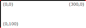
Note that in some cases the user agent will need to supply a
translate transformation in addition to a
scale transformation. For example, on an
outermost svg element, a
translate transformation will be needed if the
‘viewBox’ attributes specifies
values other than zero for <min-x> or <min-y>.
If both ‘transform’ (or ‘patternTransform’)
and ‘viewBox’ are applied to an element two new coordinate
systems are established. ‘transform’ establishes the first new
coordinate system for the element. ‘viewBox’
establishes a second coordinate system for all descendants of
the element. The first coordinate system is post-multiplied by the
second coordinate system.
Unlike the
‘transform’ property,
the automatic transformation that is created
due to a ‘viewBox’ does not affect
the ‘x’, ‘y’, ‘width’ and ‘height’ attributes (or in the case of
the ‘marker’ element, the
‘markerWidth’ and ‘markerHeight’ attributes) on the
element with the ‘viewBox’
attribute. Thus, in the example above which shows an
‘svg’ element which has
‘width’ and ‘height’ presentation attributes
and a ‘viewBox’ attribute,
the ‘width’ and ‘height’
represent values in the coordinate system that exists before the
‘viewBox’ transformation is applied. On
the other hand, like the ‘transform’ property, it does
establish a new coordinate system for all other attributes and
for descendant elements.
7.6. The ‘preserveAspectRatio’
attribute
-
| Name |
Value |
Initial value |
Animatable |
| preserveAspectRatio |
<align> <meetOrSlice>? |
xMidYMid meet |
yes |
-
<align> = none | xMinYMin | xMidYMin | xMaxYMin | xMinYMid | xMidYMid | xMaxYMid | xMinYMax | xMidYMax | xMaxYMax
<meetOrSlice> = meet | slice
Indicates whether or not to force uniform scaling. Applies to all
elements that establish a new viewport (see elements that
establish viewports), plus the
‘image’,
‘marker’,
‘pattern’ and
‘view’ elements
In some cases, typically when using the
‘viewBox’ attribute, it is desirable that the graphics stretch to
fit non-uniformly to take up the
entire viewport. In other cases, it is desirable that uniform
scaling be used for the purposes of preserving the aspect ratio
of the graphics.
For elements that establish a new viewport (see elements that
establish viewports), plus the
‘marker’,
‘pattern’ and
‘view’ elements,
‘preserveAspectRatio’ only applies when
a value has been provided for ‘viewBox’
on the same element. For these elements, if attribute
‘viewBox’ is not provided, then
‘preserveAspectRatio’ is ignored.
For ‘image’ elements,
‘preserveAspectRatio’ indicates how
referenced images should be fitted with respect to the
reference rectangle and whether the aspect ratio of the
referenced image should be preserved with respect to the
current user coordinate system.
The <align> parameter
indicates whether to force uniform scaling and, if so, the
alignment method to use in case the aspect ratio of the ‘viewBox’
doesn't match the aspect ratio of the SVG viewport. The <align> parameter must be one
of the following strings:
- none - Do not force
uniform scaling. Scale the graphic content of the given
element non-uniformly if necessary such that the element's
bounding box exactly matches the viewport rectangle.
(Note: if <align> is
none, then the optional <meetOrSlice> value is
ignored.)
- xMinYMin - Force uniform
scaling.
Align the <min-x> of
the element's ‘viewBox’ with the smallest X
value of the viewport.
Align the <min-y> of
the element's ‘viewBox’ with the smallest Y
value of the viewport.
- xMidYMin - Force uniform
scaling.
Align the midpoint X value of the element's
‘viewBox’ with the midpoint X value of the viewport.
Align the <min-y> of
the element's ‘viewBox’ with the smallest Y
value of the viewport.
- xMaxYMin - Force uniform
scaling.
Align the <min-x>+<width> of the
element's ‘viewBox’ with the maximum X value
of the viewport.
Align the <min-y> of
the element's ‘viewBox’ with the smallest Y
value of the viewport.
- xMinYMid - Force uniform
scaling.
Align the <min-x> of
the element's ‘viewBox’ with the smallest X
value of the viewport.
Align the midpoint Y value of the element's ‘viewBox’
with the midpoint Y
value of the viewport.
- xMidYMid (the initial value) -
Force uniform scaling.
Align the midpoint X value of the element's ‘viewBox’
with the midpoint X value of the viewport.
Align the midpoint Y value of the element's ‘viewBox’
with the midpoint Y value of the viewport.
- xMaxYMid - Force uniform
scaling.
Align the <min-x>+<width> of the
element's ‘viewBox’
with the maximum X value of the viewport.
Align the midpoint Y value of the element's ‘viewBox’
with the midpoint Y
value of the viewport.
- xMinYMax - Force uniform
scaling.
Align the <min-x> of
the element's ‘viewBox’ with the smallest X
value of the viewport.
Align the <min-y>+<height> of the
element's ‘viewBox’ with the maximum Y value
of the viewport.
- xMidYMax - Force uniform
scaling.
Align the midpoint X value of the element's ‘viewBox’
with the midpoint X value of the viewport.
Align the <min-y>+<height> of the
element's ‘viewBox’ with the maximum Y value
of the viewport.
- xMaxYMax - Force uniform
scaling.
Align the <min-x>+<width> of the
element's ‘viewBox’ with the maximum X value
of the viewport.
Align the <min-y>+<height> of the
element's ‘viewBox’ with the maximum Y value
of the viewport.
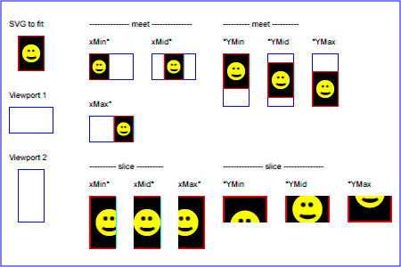
The <meetOrSlice>
parameter is optional and, if provided, is separated from the
<align> value by one or
more spaces and then must be one of the following strings:
-
meet (the default) - Scale
the graphic such that:
- aspect ratio is preserved
- the entire ‘viewBox’ is visible within
the viewport
- the ‘viewBox’ is scaled up as much
as possible, while still meeting the other criteria
In this case, if the aspect ratio of the graphic does not
match the viewport, some of the viewport will extend beyond
the bounds of the ‘viewBox’ (i.e., the area into
which the ‘viewBox’ will draw will be
smaller than the viewport).
-
slice - Scale the graphic
such that:
- aspect ratio is preserved
- the entire viewport is covered by the ‘viewBox’
- the ‘viewBox’ is scaled down as
much as possible, while still meeting the other
criteria
In this case, if the aspect ratio of the ‘viewBox’ does not match the
viewport, some of the ‘viewBox’ will extend beyond the
bounds of the viewport (i.e., the area into which the ‘viewBox’ will draw is larger
than the viewport).
Example PreserveAspectRatio
illustrates the various options on ‘preserveAspectRatio’.
The example creates several new viewports by
including ‘svg’ sub-elements embedded
inside the outermost svg element (see Establishing a new
viewport).
<svg width="450px" height="300px"
     xmlns="http://www.w3.org/2000/svg">
  <desc>Example PreserveAspectRatio - illustrates preserveAspectRatio attribute</desc>
  <defs>
	<g id="smile">
<rect x='.5' y='.5' width='29' height='39' fill='black' stroke='red'/>
<g transform='translate(0, 5)'>
<circle cx='15' cy='15' r='10' fill='yellow'/>
<circle cx='12' cy='12' r='1.5' fill='black'/>
<circle cx='17' cy='12' r='1.5' fill='black'/>
<path d='M 10 19 A 8 8 0 0 0 20 19' stroke='black' stroke-width='2'/>
</g>
</g>
</defs>
  <rect x="1" y="1" width="448" height="298"
        fill="none" stroke="blue"/>
  <g font-size="9">
    <text x="10" y="30">SVG to fit</text>
    <g transform="translate(20,40)"><use href="#smile" /></g>
    <text x="10" y="110">Viewport 1</text>
    <g transform="translate(10,120)"><rect x='.5' y='.5' width='49' height='29' fill='none' stroke='blue'/>;</g>
    <text x="10" y="180">Viewport 2</text>
    <g transform="translate(20,190)"><rect x='.5' y='.5' width='29' height='59' fill='none' stroke='blue'/>;</g>

    <g id="meet-group-1" transform="translate(100, 60)">
      <text x="0" y="-30">--------------- meet ---------------</text>
      <g><text y="-10">xMin*</text><rect x='.5' y='.5' width='49' height='29' fill='none' stroke='blue'/>;
        <svg preserveAspectRatio="xMinYMin meet" viewBox="0 0 30 40"
             width="50" height="30"><use href="#smile" /></svg></g>
      <g transform="translate(70,0)"><text y="-10">xMid*</text><rect x='.5' y='.5' width='49' height='29' fill='none' stroke='blue'/>;
        <svg preserveAspectRatio="xMidYMid meet" viewBox="0 0 30 40"
             width="50" height="30"><use href="#smile" /></svg></g>
      <g transform="translate(0,70)"><text y="-10">xMax*</text><rect x='.5' y='.5' width='49' height='29' fill='none' stroke='blue'/>;
        <svg preserveAspectRatio="xMaxYMax meet" viewBox="0 0 30 40"
             width="50" height="30"><use href="#smile" /></svg></g>
    </g>

    <g id="meet-group-2" transform="translate(250, 60)">
      <text x="0" y="-30">---------- meet ----------</text>
      <g><text y="-10">*YMin</text><rect x='.5' y='.5' width='29' height='59' fill='none' stroke='blue'/>;
        <svg preserveAspectRatio="xMinYMin meet" viewBox="0 0 30 40"
             width="30" height="60"><use href="#smile" /></svg></g>
      <g transform="translate(50, 0)"><text y="-10">*YMid</text><rect x='.5' y='.5' width='29' height='59' fill='none' stroke='blue'/>;
        <svg preserveAspectRatio="xMidYMid meet" viewBox="0 0 30 40"
             width="30" height="60"><use href="#smile" /></svg></g>
      <g transform="translate(100, 0)"><text y="-10">*YMax</text><rect x='.5' y='.5' width='29' height='59' fill='none' stroke='blue'/>;
        <svg preserveAspectRatio="xMaxYMax meet" viewBox="0 0 30 40"
             width="30" height="60"><use href="#smile" /></svg></g>
    </g>

    <g id="slice-group-1" transform="translate(100, 220)">
      <text x="0" y="-30">---------- slice ----------</text>
      <g><text y="-10">xMin*</text><rect x='.5' y='.5' width='29' height='59' fill='none' stroke='blue'/>;
        <svg preserveAspectRatio="xMinYMin slice" viewBox="0 0 30 40"
             width="30" height="60"><use href="#smile" /></svg></g>
      <g transform="translate(50,0)"><text y="-10">xMid*</text><rect x='.5' y='.5' width='29' height='59' fill='none' stroke='blue'/>;
        <svg preserveAspectRatio="xMidYMid slice" viewBox="0 0 30 40"
             width="30" height="60"><use href="#smile" /></svg></g>
      <g transform="translate(100,0)"><text y="-10">xMax*</text><rect x='.5' y='.5' width='29' height='59' fill='none' stroke='blue'/>;
        <svg preserveAspectRatio="xMaxYMax slice" viewBox="0 0 30 40"
             width="30" height="60"><use href="#smile" /></svg></g>
    </g>

    <g id="slice-group-2" transform="translate(250, 220)">
      <text x="0" y="-30">--------------- slice ---------------</text>
      <g><text y="-10">*YMin</text><rect x='.5' y='.5' width='49' height='29' fill='none' stroke='blue'/>;
        <svg preserveAspectRatio="xMinYMin slice" viewBox="0 0 30 40"
             width="50" height="30"><use href="#smile" /></svg></g>
      <g transform="translate(70,0)"><text y="-10">*YMid</text><rect x='.5' y='.5' width='49' height='29' fill='none' stroke='blue'/>;
        <svg preserveAspectRatio="xMidYMid slice" viewBox="0 0 30 40"
             width="50" height="30"><use href="#smile" /></svg></g>
      <g transform="translate(140,0)"><text y="-10">*YMax</text><rect x='.5' y='.5' width='49' height='29' fill='none' stroke='blue'/>;
        <svg preserveAspectRatio="xMaxYMax slice" viewBox="0 0 30 40"
             width="50" height="30"><use href="#smile" /></svg></g>
    </g>
  </g>
</svg>
7.7. Establishing a new SVG viewport
Note that this section handles the SVG viewport which
is different from the term "viewport" in CSS.
At any point in an SVG drawing, you can establish a new
SVG viewport into which all contained graphics is drawn by
including an ‘svg’ element
inside SVG content. By establishing a new SVG viewport, you also
implicitly establish a new viewport coordinate system, a new
user coordinate system.
Additionally, there is a new meaning for percentage units
defined to be relative to the current SVG viewport since a new
SVG viewport has been established (see Units).
The bounds of the new SVG viewport are defined by the ‘x’, ‘y’,
‘width’ and ‘height’ attributes on the element
establishing the new SVG viewport, such as an ‘svg’ element. Both the new
viewport coordinate system and the new user coordinate system
have their origins at (‘x’, ‘y’), where ‘x’ and ‘y’
represent the value of the corresponding attributes on the
element establishing the SVG viewport. The orientation of the new
viewport coordinate system and the new user coordinate system
correspond to the orientation of the current user coordinate
system for the element establishing the SVG viewport. A single unit
in the new viewport coordinate system and the new user
coordinate system are the same size as a single unit in the
current user coordinate system for the element establishing the SVG
viewport.
Here is an example:
<?xml version="1.0" standalone="no"?>
<svg width="4in" height="3in"
     xmlns="http://www.w3.org/2000/svg">
  <desc>This SVG drawing embeds another one,
    thus establishing a new SVG viewport
  </desc>
  <!-- The following statement establishing a new SVG viewport
       and renders SVG drawing B into that viewport -->
  <svg x="25%" y="25%" width="50%" height="50%">
     <!-- drawing B goes here -->
  </svg>
</svg>
For an extensive example of creating new SVG viewports, see Example
PreserveAspectRatio.
The following elements establish new SVG viewports:
- The ‘svg’ element
- A ‘symbol’ element define new
viewports whenever they are instanced by a ‘use’ element.
- An ‘image’ element that
references an SVG file will result in the establishment of a
temporary new SVG viewport since the referenced resource by
definition will have an ‘svg’ element.
- An ‘iframe’ element that references an SVG file establishes new SVG viewport like the situation of ‘image’ element.
- A ‘foreignObject’ element
creates a new SVG viewport for rendering the content that is
within the element. (It also creates a new initial containing block.)
Whether a new SVG viewport also establishes a new additional
clipping path is determined by the value of the ‘overflow’ property on the element
that establishes the new SVG viewport.
7.8. Units
SVG follows the description and definition of common values and
units from the CSS Values and Units Module
[CSS3VALUES] for attributes,
presentation attributes and CSS properties. Each attribute and property
must specify the used component value type. Subsequent or extending
specifications published by the CSS WG or SVG WG may extend basic data
types or add new data types.
For <percentage> values that are defined to be relative
to the size of viewport:
- For any x-coordinate value or width value expressed as a
percentage of the viewport, the value to use is the specified
percentage of the actual-width in user units for the
nearest containing viewport, where actual-width is
the width dimension of the viewport element within the user
coordinate system for the viewport element.
- For any y-coordinate value or height value expressed as a
percentage of the viewport, the value to use is the specified
percentage of the actual-height in user units for
the nearest containing viewport, where actual-height
is the height dimension of the viewport element within the
user coordinate system for the viewport element.
- For any other length value expressed as a percentage of
the viewport, the percentage is calculated as the specified
percentage of
sqrt((actual-width)**2 +
  (actual-height)**2)/sqrt(2)
.
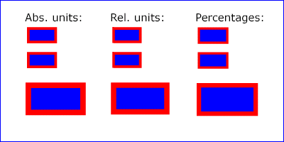
Example Units below
illustrates some of the processing rules for different types of
units.
<?xml version="1.0" standalone="no"?>
<svg width="400px" height="200px" viewBox="0 0 4000 2000"
     xmlns="http://www.w3.org/2000/svg">
  <title>Example Units</title>
  <desc>Illustrates various units options</desc>

  <!-- Frame the picture -->
  <rect x="5" y="5" width="3990" height="1990"
        fill="none" stroke="blue" stroke-width="10"/>

  <g fill="blue" stroke="red" font-family="Verdana" font-size="150">
    <!-- Absolute unit specifiers -->
    <g transform="translate(400,0)">
      <text x="-50" y="300" fill="black" stroke="none">Abs. units:</text>
      <rect x="0" y="400" width="4in" height="2in" stroke-width=".4in"/>
      <rect x="0" y="750" width="384" height="192" stroke-width="38.4"/>
      <g transform="scale(2)">
        <rect x="0" y="600" width="4in" height="2in" stroke-width=".4in"/>
      </g>
    </g>

    <!-- Relative unit specifiers -->
    <g transform="translate(1600,0)">
      <text x="-50" y="300" fill="black" stroke="none">Rel. units:</text>
      <rect x="0" y="400" width="2.5em" height="1.25em" stroke-width=".25em"/>
      <rect x="0" y="750" width="375" height="187.5" stroke-width="37.5"/>
      <g transform="scale(2)">
        <rect x="0" y="600" width="2.5em" height="1.25em" stroke-width=".25em"/>
      </g>
    </g>

    <!-- Percentages -->
    <g transform="translate(2800,0)">
      <text x="-50" y="300" fill="black" stroke="none">Percentages:</text>
      <rect x="0" y="400" width="10%" height="10%" stroke-width="1%"/>
      <rect x="0" y="750" width="400" height="200" stroke-width="31.62"/>
      <g transform="scale(2)">
        <rect x="0" y="600" width="10%" height="10%" stroke-width="1%"/>
      </g>
    </g>
  </g>
</svg>
The three rectangles on the left demonstrate the use of one
of the absolute unit identifiers, the "in" unit (inch). CSS defines 1
inch to be equal to 96 pixels. Therefore, the topmost rectangle, which is
specified in inches, is exactly the same size as the middle
rectangle, which is specified in user units such that there are
96 user units for each corresponding inch in the topmost
rectangle. The bottom rectangle of the group illustrates
what happens when values specified in inches are scaled.
The three rectangles in the middle demonstrate the use of
one of the relative unit identifiers, the "em" unit. Because
the ‘font-size’ property has been set
to 150 on the outermost ‘g’ element, each "em" unit is
equal to 150 user units. The topmost rectangle, which is
specified in "em" units, is exactly the same size as the middle
rectangle, which is specified in user units such that there are
150 user units for each corresponding "em" unit in the topmost
rectangle. The bottom rectangle of the group illustrates what
happens when values specified in "em" units are scaled.
The three rectangles on the right demonstrate the use of
percentages. Note that the width and height of the viewport in
the user coordinate system for the viewport element (in this
case, the outermost svg element) are 4000 and
2000, respectively, because processing the ‘viewBox’ attribute results in a
transformed user coordinate system. The topmost rectangle,
which is specified in percentage units, is exactly the same
size as the middle rectangle, which is specified in equivalent
user units. In particular, note that the ‘stroke-width’ property in the
middle rectangle is set to 1% of the
sqrt((actual-width)**2 +
(actual-height)**2) / sqrt(2)
, which in this
case is .01*sqrt(4000*4000+2000*2000)/sqrt(2), or 31.62. The
bottom rectangle of the group illustrates what happens when
values specified in percentage units are scaled.
7.9. Bounding boxes
- bounding box
-
The bounding box (or "bbox") of an element is the tightest fitting rectangle
aligned with the axes of that element's user coordinate system that entirely
encloses it and its descendants.
Three kinds of bounding boxes can be computed for an element:
- The object bounding box is the bounding box that contains only
an element's geometric shape. For basic shapes, this is the area
that is filled. Unless otherwise specified, this is what is meant by the
unqualified term "bounding box".
- The stroke bounding box is the bounding box that contains
an element's geometric shape and its stroke shape.
- The decorated bounding box is the bounding box that contains
an element's geometric shape, its stroke shape and its markers.
Note that the values of the ‘opacity’, ‘visibility’, ‘fill’,
‘fill-opacity’, ‘fill-rule’, ‘stroke-dasharray’
and ‘stroke-dashoffset’ properties on an element have no effect on the
bounding box of an element.
For curved shapes, the bounding box must enclose all portions of the shape
along the edge, not just end points. Note that control points for a curve which
are not defined as lying along the line of the resulting curve (e.g., the second
coordinate pair of a Cubic Bézier command) must not contribute to the dimensions
of the bounding box (though those points may fall within the area of the
bounding box, if they lie within the shape itself, or along or close to the
curve). For example, control points of a curve that are at a further distance
than the curve edge, from the non-enclosing side of the curve edge, must be
excluded from the bounding box.
Even if an element is not in the rendering tree – due to it being
'display: none', within a ‘defs’
element, not usually rendered like a ‘symbol’ element or not
currently present in the document tree – it still has a bounding box.
A call to getBBox
on the element will return the same rectangle as if the element were
rendered. However, an element that is not in the rendering tree
does not contribute to the bounding box of any ancestor element.
The following example defines a number of elements. The expected
object bounding box for each element with an ID is shown below.
<svg xmlns="http://www.w3.org/2000/svg">

  <title>Bounding Box Calculation</title>
  <desc>Examples of elements with different bounding box results based on context.</desc>

  <defs id="defs-1">
     <rect id="rect-1" x="20" y="20" width="40" height="40" fill="blue" />
  </defs>

  <g id="group-1">
    <use id="use-1" href="#rect-1" x="10" y="10" />

    <g id="group-2" display="none">
      <rect id="rect-2" x="10" y="10" width="100" height="100" fill="red" />
    </g>
  </g>
</svg>
| Element ID |
Bounding Box Result |
"defs-1" |
{0, 0, 0, 0} |
"rect-1" |
{20, 20, 40, 40} |
"group-1" |
{30, 30, 40, 40} |
"use-1" |
{30, 30, 40, 40} |
"group-2" |
{10, 10, 100, 100} |
"rect-2" |
{10, 10, 100, 100} |
For text content elements, for the purposes of the bounding box
calculation, each glyph must be treated as a separate graphics element.
he calculations must assume that all glyphs occupy the full glyph cell.
For example, for horizontal text, the calculations must assume that each glyph
extends vertically to the full ascent and descent values for the font.
An exception to this is when the ‘inline-size’ presentation
attribute has been specified on the ‘text’ element, in which case the
element's content area is its bounding box.
Because declarative or scripted animation can change the shape, size, and
position of an element, the bounding box is mutable. Thus, the bounding box
for an element shall reflect the current values for the element at the snapshot
in time at which the bounding box is requested, whether through a script call
or as part of a declarative or linking syntax.
An element which has zero width, zero height, or both (such as a
vertical or horizontal line, or a ‘rect’ element with a zero
‘width’ or ‘height’) still has a bounding box, with a
positive value for the positive dimension, or with '0'
for both the width and height if no positive dimension is specified. Similarly,
subpaths segments of a ‘path’ element with zero width and height must be
included in that element's geometry for the sake of the bounding box.
An element with no position specified (such as a
‘path’ element with a value of (none) for the ‘d’ attribute) is positioned at the
point (0,0) for the purposes of calculating a bounding box.
Note that elements whose DOM object does not derive from SVGGraphicsElement
(such as gradient elements) do not have a bounding box, and thus have no
interface to request a bounding box.
Elements in the rendering tree which reference unresolved resources shall
still have a bounding box, defined by the position and dimensions specified in
their attributes, or by the initial value for those attributes if no
values are supplied. For example, the element <use href="#bad" x="10" y="10"/>
would have a bounding box with an x and y of 10 and a width and height of 0.
The following algorithm defines how to compute a bounding box for a given
element. The inputs to the algorithm are:
- element, the element we are computing a bounding box for;
- space, a coordinate space in which the bounding box will be computed;
- fill, a boolean indicating whether the bounding box includes the geometry of the element and its descendants;
- stroke, a boolean indicating whether the bounding box includes the stroke of the element and its descendants;
- markers, a boolean indicating whether the bounding box includes the markers of the element and its descendants; and
- clipped, a boolean indicating whether the bounding box is affected by any clipping paths applied to the element and its descendants.
Need to define what the union of rectangles with no area means.
The algorithm to compute the bounding box is as follows, depending on the type of element:
- a shape
- a text content element
- an ‘a’ element within a text content element
-
- Let box be a rectangle initialized to (0, 0, 0, 0).
- Let fill-shape be the equivalent path of element
if it is a shape, or a shape that includes each of the glyph cells corresponding
to the text within the elements otherwise.
Need to update this take into account ‘inline-size’
on ‘text’.
- If fill is true, then set box to the tightest rectangle
in the coordinate system space that contains fill-shape.
The values of the ‘fill’, ‘fill-opacity’ and ‘fill-rule’
properties do not affect fill-shape.
- If stroke is true and the element's ‘
stroke’ is anything other than
none, then set box to be the union of box and the
tightest rectangle in coordinate system space that contains the stroke shape of the
element, with the assumption that the element has no dash pattern.
The values of the ‘stroke-opacity’, ‘stroke-dasharray’
and ‘stroke-dashoffset’ do not affect the calculation of the stroke shape.
- If markers is true, then for each marker marker rendered on the element:
- For each descendant graphics element child of the ‘marker’ element
that defines marker's content:
- If child has an ancestor element within the ‘marker’ that is
'display: none', has a failing conditional processing attribute,
or is not an ‘a’, ‘g’, ‘svg’ or ‘switch’ element, then
continue to the next descendant graphics element.
- Otherwise, set box to be the union of box and the result of invoking the
algorithm to compute a bounding box with child as the element,
space as the target coordinate space, true for fill,
stroke and markers, and clipped for clipped.
Need to determine whether 'display: none' on the
‘marker’ element itself has any effect here.
- If clipped is true and the value of ‘
clip-path’ on element is not
none, then set box to be the tighest rectangle
in coordinate system space that contains the intersection of box and the clipping path.
- Return box.
- a container element
- ‘use’
-
- Let box be a rectangle initialized to (0, 0, 0, 0).
- Let parent be the container element if it is one, or the
root of the ‘use’ element's shadow tree otherwise.
- For each descendant graphics element child of parent:
- If child has an ancestor element within parent that is
'display: none', has a failing conditional processing attribute,
or is not an ‘a’, ‘g’, ‘svg’ or ‘switch’ element, then
continue to the next descendant graphics element.
- Otherwise, set box to be the union of box and the result of invoking the
algorithm to compute a bounding box with child as the element
and the same values for space, fill, stroke,
markers and clipped as the corresponding algorithm input values.
- Return box.
- ‘canvas’
- ‘foreignObject’
- ‘iframe’
- ‘image’
- ‘video’
-
- Return the tightest rectangle in coordinate space space that
contains the rectangle defined by the
‘x’,
‘y’,
‘width’ and
‘height’ attributes of the element.
The fill, stroke and markers
input arguments to this algorithm do not affect the bounding box returned
for these elements.
The object bounding box, stroke bounding box or decorated bounding box
of an element is the result of invoking the bounding box computation algorithm
above with the following arguments:
element is the element itself;
space is the element's user coordinate system;
fill is true;
stroke is true if we are computing the stroke bounding box or decorated bounding box, and false othwerise;
markers is true if we are computing the decorated bounding box, and false otherwise; and
clipped is false.
7.10. Object bounding box units
The following elements offer the option of expressing
coordinate values and lengths as fractions (and, in some cases,
percentages) of the object bounding box,
by setting a specified attribute to 'objectBoundingBox'
on the given element:
| Element |
Attribute |
Effect |
| ‘linearGradient’ |
‘gradientUnits’ |
Indicates that the attributes which specify the
gradient vector (‘x1’, ‘y1’, ‘x2’, ‘y2’) represent fractions or
percentages of the bounding box of the element to which the
gradient is applied. |
| ‘radialGradient’ |
‘gradientUnits’ |
Indicates that the attributes which specify the center
(‘cx’, ‘cy’), the radius (‘r’) and focus
(‘fx’, ‘fy’) represent fractions or
percentages of the bounding box of the element to which the
gradient is applied. |
| ‘mesh’ |
‘gradientUnits’ |
Indicates that the attributes which specify the paint server mesh
(‘x’, ‘y’) represent fractions or percentages of the
bounding box of the element to which the mesh is applied. (Gets ignored
if the mesh is a graphics object) |
| ‘pattern’ |
‘patternUnits’ |
Indicates that the attributes which define how to tile the pattern
(‘x’, ‘y’, ‘width’, ‘height’) are
established using the bounding box of the element to which the pattern
is applied. |
| ‘pattern’ |
‘patternContentUnits’ |
Indicates that the user coordinate system for the
contents of the pattern is established using the bounding
box of the element to which the pattern is applied. |
| ‘clipPath’ |
‘clipPathUnits’ |
Indicates that the user coordinate system for the contents of the
‘clipPath’ element is established using the bounding box of the
element to which the clipping path is applied. |
| ‘mask’ |
‘maskUnits’ |
Indicates that the attributes which define the masking region
(‘x’, ‘y’, ‘width’, ‘height’) is
established using the bounding box of the element to which the mask
is applied. |
| ‘mask’ |
‘maskContentUnits’ |
Indicates that the user coordinate system for the contents of
the ‘mask’ element are established using the bounding box of
the element to which the mask is applied. |
| ‘filter’ |
‘filterUnits’ |
Indicates that the attributes which define the
filter effects region
(‘x’, ‘y’, ‘width’, ‘height’) represent
fractions or percentages of the bounding box of the element to which
the filter is applied. |
| ‘filter’ |
‘primitiveUnits’ |
Indicates that the various length values within the filter
primitives represent fractions or percentages of the bounding box of
the element to which the filter is applied. |
In the discussion that follows, the term applicable element
is the element to which the given effect applies. For gradients and
patterns, the applicable element is the graphics element
which has its ‘fill’ or ‘stroke’ property referencing the
given gradient or pattern. (See Inheritance
of Painting Properties. For special rules concerning text elements, see the discussion of object
bounding box units and text elements.) For clipping paths,
masks and filters, the applicable element can be either a
container element or a graphics element.
When keyword objectBoundingBox is used, then the
effect is as if a supplemental transformation matrix were
inserted into the list of nested transformation matrices to
create a new user coordinate system.
First, the (minx,miny) and
(maxx,maxy) coordinates are
determined by the extends of the object bounding box of
the applicable element.
Then, coordinate (0,0) in the new user coordinate system is
mapped to the (minx,miny) corner of the tight bounding box
within the user coordinate system of the applicable element and
coordinate (1,1) in the new user coordinate system is mapped to
the (maxx,maxy) corner of the tight bounding box of the
applicable element. In most situations, the following
transformation matrix produces the correct effect:
[ (maxx-minx) 0 0 (maxy-miny) minx miny ]
When percentages are used with attributes that define the
gradient vector, the pattern tile, the filter region or the
masking region, a percentage represents the same value as the
corresponding decimal value (e.g., 50% means the same as 0.5).
If percentages are used within the content of a ‘pattern’,
‘clipPath’, ‘mask’ or ‘filter’ element, these values
are treated according to the processing rules for percentages
as defined in Units.
Any numeric value can be specified for values expressed as a
fraction or percentage of object bounding box units. In
particular, fractions less are zero or greater than one and
percentages less than 0% or greater than 100% can be
specified.
Keyword objectBoundingBox
should not be used when the geometry of the applicable element
has no width or no height, such as the case of a horizontal or
vertical line, even when the line has actual thickness when
viewed due to having a non-zero stroke width since stroke width
is ignored for bounding box calculations. When the geometry of
the applicable element has no width or height and objectBoundingBox is specified, then
the given effect (e.g., a gradient or a filter) will be
ignored.
SVG needs to specify how to calculate some intrinsic sizing properties to
enable inclusion within other host documents. The intrinsic width and height
of the SVG viewport of SVG content must be determined from the ‘width’
and ‘height’ properties. If either of these are not specified,
the used value is the initial value 'auto'.
Specifically, percentage values do not provide an intrinsic width or height.
In this case the intrinsic aspect ratio is 1:1.
In this example, the intrinsic aspect ratio is 1:1.
This interface defines a list of SVGTransform objects.
Used for the various attributes which specify a set of transformations,
such as the ‘transform’ presentation attribute which is available for many of
SVG's elements, and which can be animated.
