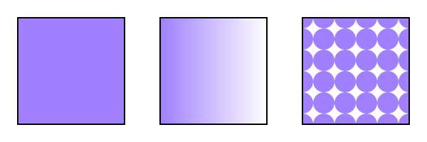
Three types of paint servers. From left to right: A solid color ("MyLightPurple"). A linear gradient. A pattern.
This section covers Paint Servers, a method which
allows the ‘fill’ or ‘stroke’ of an object to be defined
by a resource found elsewhere. It allows resources to be reused
throughout a document. See the section
Painting: Filling and Stroking for a
general discussion of filling and stroking objects.
SVG defines three types of paint servers:
SVG1.1 refers to "built-in" paint servers. Is there any other kind?
| SVG 2 Requirement: | Support hatching. |
|---|---|
| Resolution: | SVG 2 should support hatching without the artifacts that patterns currently impose. |
| Purpose: | To allow the kinds of patterns required for mapping, engraving, etc. where continuous lines are required. |
| Owner: | Tav (no action) |
| SVG 2 Requirement: | Arbitrary fills for shapes. |
|---|---|
| Resolution: | SVG 2 shall support filling and stroking from arbitrary elements. |
| Purpose: | To allow for example videos or images to be used as a fill source. |
| Owner: | Alex? (no action) |
It seems that all paint servers (except perhaps, mesh gradients, when rendered directly) inherit from their ancestors and do not inherit from the element referencing the paint server. Rather than repeating this for each type of paint server, can the text be moved into the introduction section for paint servers?
Three types of paint servers. From left to right: A solid color ("MyLightPurple"). A linear gradient. A pattern.
Paint servers are used by including an IRI reference in
a ‘fill’ or ‘stroke’ property (i.e. fill="#MyLightPurple").
Solid Colors are new in SVG 2 (ported from SVG 1.2 Tiny).
| SVG 2 Requirement: | Support named colors. |
|---|---|
| Resolution: | Will add ‘solidColor’ element to SVG 2. |
| Purpose: | To provide an easy mechanism for creating named colors and palettes. Also useful for animation. |
| Owner: | Tav (no action) |
The 'solidColor' element is a paint server that provides a single color with opacity. It can be referenced any place a single color can be used. The 'solidColor' element allows a palette to be defined and used consistently throughout a document. It is also useful as away of animating a palette colors. (See the chapter Color for a more general discussion of color in SVG.)
Properties inherit into the ‘solidColor’ element from its ancestors; properties do not inherit from the element referencing the ‘solidColor’ element.
‘solidColor’ elements are never rendered directly;
their only usage is as something that can be referenced using the
‘fill’ and ‘stroke’ properties. The ‘display’
property does not apply to the ‘solidColor’ element; thus,
‘solidColor’ elements are not directly rendered even if
the ‘display’ property is set to a value other than
none, and ‘solidColor’
elements are available for referencing even when the ‘display’
property on the ‘solidColor’ element or any of its ancestors
is set to none.
Solid colors are defined by a ‘solidColor’ element.
The ‘solid-color’ property specifies the color of
the ‘solidColor’. The keyword
currentColor and ICC colors
can be specified in the same manner as within a
<paint>
specification for the ‘fill’ and ‘stroke’
properties.
solid-color’ elements
The ‘solid-opacity’ property defines the opacity of
the ‘solidColor’.
solid-color’ elementsfill’ or ‘stroke’.
<?xml version="1.0" standalone="no"?>
<svg xmlns="http://www.w3.org/2000/svg"
     version="2.0"
     viewBox="0 0 300 100" >

  <title>Example solidColor</title>
  <desc>Fill objects using a solidColor paint server.</desc>

  <defs>
    <solidColor id="MyLightPurple" solid-color="#a080ff" solid-opacity="0.5"/>
  </defs>

  <!-- The shapes are filled using a solidColor paint server -->
  <circle fill="url(#MyLightPurple)" cx="50" cy="50" r="40"/>
  <rect   fill="url(#MyLightPurple)" x="110" y="10" width="80" height="80"/>
  <path   fill="url(#MyLightPurple)" d="m 250 10 l 40 80 -80 0 z"/>
</svg>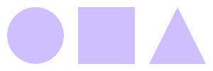
Example solidcolor.svg
Gradients consist of smooth color transitions between points on a drawing surface. SVG provides for three types of gradients:
Once a gradient is defined, a graphics element can be
filled or stroked with the gradient by setting the ‘fill’
or ‘stroke’ properties to reference the gradient.
Color transitions for linear and radial gradients are defined by a series of color stops along a gradient vector. A gradient normal defines how the colors in a vector are painted to the surface. For a linear gradient, the normal corresponds to lines with the same color. It is perpendicular to the vector in an untransformed gradient. When a graphics element references a gradient, conceptually the graphics element should take a copy of the gradient vector and gradient normal and treat it as part of its own geometry. Any transformations applied to the graphics element geometry also apply to the copied gradient vector and gradient normal. Any gradient transforms that are specified on the reference gradient are applied before any graphics element transformations are applied to the gradient.
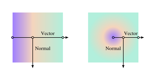
Linear and radial gradients with the gradient vector and gradient normal indicated. The vector consists of three stops shown by small circles.
Would it be better to just refer to the normal as the line where color is constant. In this case, it would be a circle for an untransformed radial gradient.
Alternative figure:
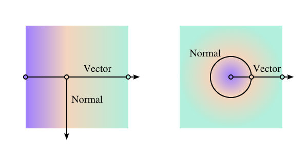
Linear and radial gradients with the gradient vector indicated. The vector consists of three stops shown by small circles. One gradient normal is shown for each gradient.
Color transitions for mesh gradients are defined by an array of color stops. The mapping of colors to the drawing surface in this case is done by geometric data located in the stops. This is discussed in detail in the mesh gradients section.
Linear gradients are defined by a ‘linearGradient’ element.
Defines the coordinate system for attributes ‘x1’, ‘y1’, ‘x2’ and ‘y2’.
If gradientUnits="userSpaceOnUse",
‘x1’, ‘y1’, ‘x2’, and ‘y2’
represent values in the coordinate system that results
from taking the current user coordinate system in place at
the time when the gradient element is referenced (i.e.,
the user coordinate system for the element referencing the
gradient element via a ‘fill’ or ‘stroke’
property) and then applying the transform specified by
attribute ‘gradientTransform’. Percentages
represent values relative to the current viewport.
If gradientUnits="objectBoundingBox", the user coordinate system for attributes ‘x1’, ‘y1’, ‘x2’ and ‘y2’ is established using the bounding box of the element to which the gradient is applied (see Object bounding box units) and then applying the transform specified by attribute ‘gradientTransform’. Percentages represent values relative to the bounding box for the object.
When gradientUnits="objectBoundingBox" and ‘gradientTransform’ is the identity matrix, the normal of the linear gradient is perpendicular to the gradient vector in object bounding box space (i.e., the abstract coordinate system where (0,0) is at the top/left of the object bounding box and (1,1) is at the bottom/right of the object bounding box). When the object's bounding box is not square, the gradient normal which is initially perpendicular to the gradient vector within object bounding box space may render non-perpendicular relative to the gradient vector in user space. If the gradient vector is parallel to one of the axes of the bounding box, the gradient normal will remain perpendicular. This transformation is due to application of the non-uniform scaling transformation from bounding box space to user space.
Contains the definition of an optional additional transformation from the gradient coordinate system onto the target coordinate system (i.e., 'userSpaceOnUse' or 'objectBoundingBox'). This allows for things such as skewing the gradient. This additional transformation matrix is post-multiplied to (i.e., inserted to the right of) any previously defined transformations, including the implicit transformation necessary to convert from object bounding box units to user space.
‘x1’, ‘y1’, ‘x2’ and ‘y2’ define a gradient vector for the linear gradient. This gradient vector provides starting and ending points onto which the gradient stops are mapped. The values of ‘x1’, ‘y1’, ‘x2’ and ‘y2’ can be either numbers or percentages.
See ‘x1’.
See ‘x1’.
See ‘x1’.
SVG 1.1 2nd edition has lacuna value="0%".
Indicates what happens if the gradient starts or ends inside the bounds of the target rectangle.
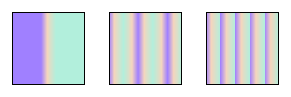
Illustration of the three possible values for spreadMethod, from left to right: pad, reflect, repeat. The gradient vector spans from 40% to 60% of the bounding box width.
An IRI reference to a different ‘linearGradient’ or ‘radialGradient’ element within the current SVG document fragment. Any ‘linearGradient’ attributes which are defined on the referenced element which are not defined on this element are inherited by this element. If this element has no defined gradient stops, and the referenced element does (possibly due to its own ‘xlink:href’ attribute), then this element inherits the gradient stop from the referenced element. Inheritance can be indirect to an arbitrary level; thus, if the referenced element inherits attribute or gradient stops due to its own ‘xlink:href’ attribute, then the current element can inherit those attributes or gradient stops.
If ‘x1’ = ‘x2’ and ‘y1’ = ‘y2’, then the area to be painted will be painted as a single color using the color and opacity of the last gradient stop.
Properties inherit into the ‘linearGradient’ element from its ancestors; properties do not inherit from the element referencing the ‘linearGradient’ element.
‘linearGradient’ elements are never rendered directly;
their only usage is as something that can be referenced using the
‘fill’ and ‘stroke’ properties. The ‘display’
property does not apply to the ‘linearGradient’ element; thus,
‘linearGradient’ elements are not directly rendered even if
the ‘display’ property is set to a value other than
none, and ‘linearGradient’
elements are available for referencing even when the ‘display’
property on the ‘linearGradient’ element or any of its ancestors
is set to none.
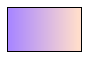
Example lingrad01 shows how to fill a rectangle by referencing a linear gradient paint server.
<?xml version="1.0" standalone="no"?>
<svg xmlns="http://www.w3.org/2000/svg"
     version="1.1"
     viewBox="0 0 300 200" >

  <title>Example lingrag01</title>
  <desc>Fill a rectangle using a linear-gradient paint server.</desc>

  <defs>
    <linearGradient id="MyGradient">
      <stop offset="5%" stop-color="#A8F" />
      <stop offset="95%" stop-color="#FDC" />
    </linearGradient>
  </defs>

  <!-- The rectangle is filled using a linear-gradient paint server -->
  <rect fill="url(#MyGradient)"
	stroke="black"
	stroke-width="2"
	x="25" y="25" width="250" height="150"/>
</svg>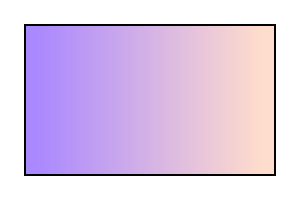
Example lingrad01
Radial gradients are defined by a ‘radialGradient’ element.
Defines the coordinate system for attributes ‘cx’, ‘cy’, ‘r’, ‘fx’, ‘fy’, and ‘fr’.
If gradientUnits="userSpaceOnUse",
‘cx’, ‘cy’, ‘r’, ‘fx’, ‘fy’,
and ‘fr’
represent values in the coordinate system that results
from taking the current user coordinate system in place at
the time when the gradient element is referenced (i.e.,
the user coordinate system for the element referencing the
gradient element via a ‘fill’ or ‘stroke’
property) and then applying the transform specified by
attribute ‘gradientTransform’. Percentages
represent values relative to the current viewport.
If gradientUnits="objectBoundingBox", the user coordinate system for attributes ‘cx’, ‘cy’, ‘r’, ‘fx’, ‘fr’, and ‘fr’ is established using the bounding box of the element to which the gradient is applied (see Object bounding box units) and then applying the transform specified by attribute ‘gradientTransform’. Percentages represent values relative to the bounding box for the object.
When gradientUnits="objectBoundingBox" and ‘gradientTransform’ is the identity matrix, then the rings of the radial gradient are circular with respect to the object bounding box space (i.e., the abstract coordinate system where (0,0) is at the top/left of the object bounding box and (1,1) is at the bottom/right of the object bounding box). When the object's bounding box is not square, the rings that are conceptually circular within object bounding box space will render as elliptical due to application of the non-uniform scaling transformation from bounding box space to user space.
Contains the definition of an optional additional transformation from the gradient coordinate system onto the target coordinate system (i.e., 'userSpaceOnUse' or 'objectBoundingBox'). This allows for things such as skewing the gradient. This additional transformation matrix is post-multiplied to (i.e., inserted to the right of) any previously defined transformations, including the implicit transformation necessary to convert from object bounding box units to user space.
‘cx’, ‘cy’ and ‘r’ define the largest (i.e., outermost) circle for the radial gradient. The gradient will be drawn such that the 100% gradient stop is mapped to the perimeter of this largest circle.
See ‘cx’.
See ‘cx’.
A negative value is an error (see Error processing). A value of zero will cause the area to be painted as a single color using the color and opacity of the last gradient stop.
‘fx’, ‘fy’, and ‘fr’ define the smallest (i.e., innermost) circle for the radial gradient. The gradient will be drawn such that the 0% gradient stop is mapped to the perimeter of this smallest circle.
If attribute ‘fx’ is not specified, ‘fx’ will coincide with the presentational value of ‘cx’ for the element whether the value for 'cx' was inherited or not. If the element references an element that specifies a value for 'fx', then the value of 'fx' is inherited from the referenced element.
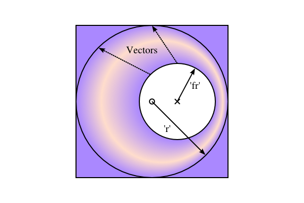
This diagram shows how the geometric attributes are defined for the case where ‘fr’ is 50% of ‘r’. The small circle marks the center of the outermost circle (‘cx’,‘cy’), while the cross marks the center of the innermost circle (‘fx’,‘fy’). The dashed lines show two gradient vectors. Vectors connect corresponding points on the inner and outer most circles.
See ‘fx’.
If attribute ‘fy’ is not specified, ‘fy’ will coincide with the presentational value of ‘cy’ for the element whether the value for 'cy' was inherited or not. If the element references an element that specifies a value for 'fy', then the value of 'fy' is inherited from the referenced element.
New in SVG 2. Added to align with Canvas.
‘fr’ is the radius of the focal circle. See ‘fx’.
If the attribute is not specified, the effect is as if a value of '0%' were specified. If the element references an element that specifies a value for 'fr', then the value of 'fr' is inherited from the referenced element.
| SVG 2 Requirement: | Allow specifying focal circle radius in radial gradients. |
|---|---|
| Resolution: | Add an ‘fr’ attribute to ‘radialGradient’> for SVG 2. |
| Purpose: | To align with Canvas. The zero-offset stop would be along the circle defined by the ‘fx’, ‘fy’ and ‘fr’ attributes. |
| Owner: | Erik (ACTION-3098) |
Indicates what happens if the gradient starts or ends inside the bounds of the object(s) being painted by the gradient. Has the same values and meanings as the ‘spreadMethod’ attribute on ‘linearGradient’ element.
An IRI reference to a different ‘linearGradient’ or ‘radialGradient’ element within the current SVG document fragment. Any ‘radialGradient’ attributes which are defined on the referenced element which are not defined on this element are inherited by this element. If this element has no defined gradient stops, and the referenced element does (possibly due to its own ‘xlink:href’ attribute), then this element inherits the gradient stop from the referenced element. Inheritance can be indirect to an arbitrary level; thus, if the referenced element inherits attribute or gradient stops due to its own ‘xlink:href’ attribute, then the current element can inherit those attributes or gradient stops.
| SVG 2 Requirement: | Clarify radial gradients with focal point on the circle. |
|---|---|
| Resolution: | When the focal point is on the circle edge, with repeat, then the distance between the first and last stop for the repeating colors is 0 and the paint should generate a color that is the average of all the gradient stops. |
| Purpose: | To improve interoperability of radial gradients. |
| Owner: | Erik (ACTION-3097) |
| Note: | SVG 1.1 does not define what to do when the focal point is on the circle edge, with 'repeat'. The distance between the first and last stop for the repeating colors is 0. It was resolved that the paint should generate a color that is the weighted average (by offset) of all the gradient stops. |
If the point defined by ‘fx’ and ‘fy’ lies outside the circle defined by ‘cx’, ‘cy’, and ‘r’, then the user agent shall set the focal point to the intersection of the line from (‘cx’, ‘cy’) to (‘fx’, ‘fy’) with the circle defined by ‘cx’, ‘cy’, and ‘r’.
What happens if the circle defined by 'fx', 'fy', and 'fr' crosses outside of the circle defined by 'cx', 'cy', and 'cr'?
What color space is the weighted average performed (linearRGB/sRGB)?
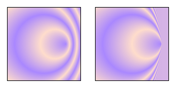
Two radial gradients with spreadMethod="repeat". On the left, the focus is just inside the right side of the circle defined by by ‘cx’, ‘cy’, and ‘r’. On the right, the focus is on the circle. In this case, the area painted to the right of the circumference has a fill equal to the weighted average of the colors in the gradient vector.
Properties inherit into the ‘radialGradient’ element from its ancestors; properties do not inherit from the element referencing the ‘radialGradient’ element.
‘radialGradient’ elements are never rendered directly;
their only usage is as something that can be referenced using the
‘fill’ and ‘stroke’ properties. The ‘display’
property does not apply to the ‘radialGradient’ element; thus,
‘radialGradient’ elements are not directly rendered even if
the ‘display’ property is set to a value other than
none, and ‘radialGradient’ elements
are available for referencing even when the ‘display’ property on
the ‘radialGradient’ element or any of its ancestors is set to
none.
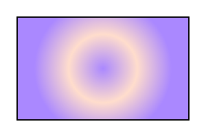
Example radgrad01 shows how to fill a rectangle by referencing a radial gradient paint server.
<?xml version="1.0" standalone="no"?>
<svg xmlns="http://www.w3.org/2000/svg"
     version="1.1"
     viewBox="0 0 300 200" >
  <title>Example radgrad01</title>
  <desc>Fill a rectangle by referencing a radial gradient paint server.</desc>

  <defs>
    <radialGradient id="MyGradient"
		    gradientUnits="userSpaceOnUse"
		    cx="150" cy="100"
		    r="100">
      <stop offset="0%"   stop-color="#A8F" />
      <stop offset="50%"  stop-color="#FDC" />
      <stop offset="100%" stop-color="#A8F" />
    </radialGradient>
  </defs>

  <!-- The rectangle is filled using a radial gradient paint server -->
  <rect fill="url(#MyGradient)"
	stroke="black"
	stroke-width="2"
	x="25" y="25" width="250" height="150"/>
</svg>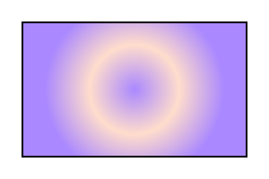
Example radgrad01
New in SVG 2. Added to allow shadings along curved lines. This is needed, for example, in creating life-like drawings.
The mesh gradients in SVG are based on an array of Coons Patches. A Coons Patch is a shading defined by colors place at the corners of an area enclosed by four Bézier curves.
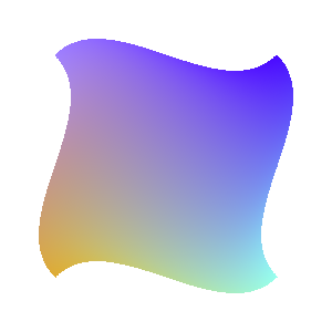
A single Coons-Mesh patch.
A Coons Patch is equivalent to a bi-cubic Ferguson patch where the distance between a cubic Bézier end point and its nearest control point is one-third the length of the corresponding Ferguson tangent line.
The corner colors are mapped to the patch area with a two step process. First the colors are placed at the corners of a unit square the area inside the square is colored using a bilinear interpolation. Second, the points inside the square are mapped to points inside the patch using the following formula (u, and v are the coordinates inside the unit square):
S = SC + SD − SB, where
SC(u,v) = (1−v)×C1(u) + v×C2(u),
SD(u,v) = (1−u)×D1(v) + u×D2(v), and
SB(u,v) = (1−v)×[(1-u)×C1(0) + u×C1(1)]
             +  v×[(1−u)×C2(0) + u×C2(1)].
MathML gets stripped out by build script.
<math xmlns="http://www.w3.org/1998/Math/MathML">
  <mrow>
    <msup><mi>S</mi></msup><mo>=</mo><mi>S</mi><msub>C</msub><mo>+</mo><mi>S</mi><msub>D</msub>
  </mrow>
</math>
Come up with better explanation of the mapping with diagram. The subtraction term in the above formula ensures that the boundary conditions are met.
One method of rendering a patch is to "divide and conquer." Check if the four corner colors of the patch are the same within a specified tolerance. If so, paint the patch with the average color using the normal path filling routine. If not, divide the patch into four smaller patches and repeat the color tolerance check. Repeat the process as many times as necessary.
Another way to render a patch is to first divide the patch vertically or horizontally into a series of smaller patches that are each less than one pixel high or wide. Then each resulting patch can be rendered as a path.
For a mesh, the individual patches are placed in an array. There are two reasons for using an array. The first is that an array of meshes is a natural result for most content creation processes (start with a path and then subdivide its area into rows and columns of patches). The second is that the data can be compacted by sharing sides and corners. The array structure is conceptual only. The actual mesh can be distorted in any way possible. The mesh gradient syntax is designed so that it is easy to simulate other types of gradients such as conical gradients or triangle meshes as shown in the examples below.
The structure of a mesh gradient is as follows:
<meshGradient x="100" y="100">
  <meshRow>
    <meshPatch>
      <stop .../>
        Up to four stops in first patch. See details below.
    </meshPatch>
    <meshPatch>
      Any number of meshPatches in row.
    </meshPatch>
  </meshRow>
  <meshRow>
    Any number of meshRows, each with the same number of meshPatches as in the first row.
  </meshRow>
</meshGradient>
| SVG 2 Requirement: | Support photorealistic gradients. |
|---|---|
| Resolution: | Mesh gradients are accepted by the WG for SVG 2. |
| Purpose: | To allow more complex gradients such as those found in nature. |
| Owner: | Tav (ACTION-3121) |
Resolution: Rename stop-path to 'd' or 'path' (Coons patch syntax).
Resolution: We will allow just C/c/L/l in mesh path data. We will leave out tensor control points. We will not allow multiple colors at mesh intersections, just use zero size patches instead.
Mesh gradients are defined by a ‘meshGradient’ element.
TODO: Define ‘x’, ‘y’, ‘gradientUnits’ ‘gradientTransform’ and ‘href’ attributes.
Mesh rows are defined by a ‘meshRow’ element.
Mesh patches are defined by a ‘meshPatch’ element.
The vector (linear and radial gradients) or array (mesh gradients) of colors to use in a gradient is defined by the ‘stop’ elements that are child elements to a ‘linearGradient’, ‘radialGradient’, or ‘meshPatch’ element.
In SVG 1.1, the above read: "The ramp of colors..." but "ramp" is used nowhere else in this section.
Indicates were the gradient stop is placed. For linear gradients, the ‘offset’ attribute represents a location along the gradient vector. For radial gradients, it represents a fractional distance from the edge of the innermost/smallest circle to the edge of the outermost/largest circle. This attribute does not apply to mesh gradients.
Gives the path for one side of a mesh gradient patch. This attribute applies only to mesh gradients.
A description of mesh path data.
The ‘stop-color’ property indicates what color to use
at that gradient stop. The keyword
currentColor and ICC colors
can be specified in the same manner as within a
<paint>
specification for the ‘fill’ and ‘stroke’
properties.
The ‘stop-opacity’ property defines the opacity of
a given gradient stop.
fill’ or ‘stroke’.
If two gradient stops have the same offset value, then the latter gradient stop controls the color value at the overlap point. In particular:
<stop offset="0" stop-color="white"/>
<stop offset=".2" stop-color="red"/>
<stop offset=".2" stop-color="blue"/>
<stop offset="1" stop-color="black"/>
will have approximately the same effect as:
<stop offset="0" stop-color="white"/>
<stop offset=".1999999999" stop-color="red"/>
<stop offset=".2" stop-color="blue"/>
<stop offset="1" stop-color="black"/>
which is a gradient that goes smoothly from white to red, then abruptly shifts from red to blue, and then goes smoothly from blue to black.
A pattern is used to ‘fill’ or ‘stroke’
an object using a pre-defined graphic object which can be replicated
("tiled") at fixed intervals in x and y to cover the
areas to be painted. Patterns are defined using a ‘pattern’
element and then referenced by properties ‘fill’ and
‘stroke’ on a given graphics element to indicate that the
given element shall be filled or stroked with the pattern.
Attributes ‘x’, ‘y’, ‘width’, ‘height’ and ‘patternUnits’ define a reference rectangle somewhere on the infinite canvas. The reference rectangle has its top/left at (x, y) and its bottom/right at (x + width, y + height). The tiling theoretically extends a series of such rectangles to infinity in X and Y (positive and negative), with rectangles starting at (x + m*width, y + n* height) for each possible integer value for m and n.
Defines the coordinate system for attributes ‘x’, ‘y’, ‘width’ and ‘height’.
If patternUnits="userSpaceOnUse",
‘x’, ‘y’, ‘width’ and ‘height’
represent values in the coordinate system that results
from taking the current user coordinate system in place at
the time when the ‘pattern’ element is referenced
(i.e., the user coordinate system for the element
referencing the ‘pattern’ element via a
‘fill’ or ‘stroke’ property) and then
applying the transform specified by attribute
‘patternTransform’. Percentages
represent values relative to the current viewport.
If patternUnits="objectBoundingBox", the user coordinate system for attributes ‘x’, ‘y’, ‘width’ and ‘height’ is established using the bounding box of the element to which the pattern is applied (see Object bounding box units) and then applying the transform specified by attribute ‘patternTransform’. Percentages represent values relative to the bounding box for the object.
Defines the coordinate system for the contents of the ‘pattern’. Note that this attribute has no effect if attribute ‘viewBox’ is specified.
If patternContentUnits="userSpaceOnUse",
the user coordinate system for the contents of the ‘pattern’
element is the coordinate system that results from taking
the current user coordinate system in place at the time
when the ‘pattern’ element is referenced (i.e., the
user coordinate system for the element referencing the
‘pattern’ element via a ‘fill’ or ‘stroke’
property) and then applying the transform specified by attribute
‘patternTransform’.
If patternContentUnits="objectBoundingBox", the user coordinate system for the contents of the ‘pattern’ element is established using the bounding box of the element to which the pattern is applied (see Object bounding box units) and then applying the transform specified by attribute ‘patternTransform’.
Contains the definition of an optional additional transformation from the pattern coordinate system onto the target coordinate system (i.e., 'userSpaceOnUse' or 'objectBoundingBox'). This allows for things such as skewing the pattern tiles. This additional transformation matrix is post-multiplied to (i.e., inserted to the right of) any previously defined transformations, including the implicit transformation necessary to convert from object bounding box units to user space.
‘x’, ‘y’, ‘width’ and ‘height’ indicate how the pattern tiles are placed and spaced. These attributes represent coordinates and values in the coordinate space specified by the combination of attributes ‘patternUnits’ and ‘patternTransform’.
See ‘x’.
See ‘x’.
A negative value is an error (see Error processing). A value of zero disables rendering of the element (i.e., no paint is applied).
See ‘x’.
A negative value is an error (see Error processing). A value of zero disables rendering of the element (i.e., no paint is applied).
An IRI reference to a different ‘pattern’ element within the current SVG document fragment. Any attributes which are defined on the referenced element which are not defined on this element are inherited by this element. If this element has no children, and the referenced element does (possibly due to its own ‘xlink:href’ attribute), then this element inherits the children from the referenced element. Inheritance can be indirect to an arbitrary level; thus, if the referenced element inherits attributes or children due to its own ‘xlink:href’ attribute, then the current element can inherit those attributes or children.
See ‘preserveAspectRatio’.
SVG's user agent style sheet sets
the ‘overflow’ property for ‘pattern’ elements to
hidden, which causes a rectangular clipping
path to be created at the bounds of the pattern tile. Unless the
‘overflow’ property is overridden, any graphics within the pattern
which goes outside of the pattern rectangle will be clipped. Note that if
the ‘overflow’ property is set to visible
the rendering behavior for the pattern is undefined.
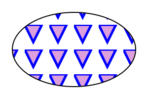
Example pattern01 below shows the
effect of clipping to the pattern tile.
The contents of the ‘pattern’ are relative to a new coordinate system. If there is a ‘viewBox’ attribute, then the new coordinate system is fitted into the region defined by the ‘x’, ‘y’, ‘width’, ‘height’ and ‘patternUnits’ attributes on the ‘pattern’ element using the standard rules for ‘viewBox’ and ‘preserveAspectRatio’. If there is no ‘viewBox’ attribute, then the new coordinate system has its origin at (x, y), where x is established by the ‘x’ attribute on the ‘pattern’ element, and y is established by the ‘y’ attribute on the ‘pattern’ element. Thus, in the following example:
<pattern x="10" y="10" width="20" height="20">
  <rect x="5" y="5" width="10" height="10"/>
</pattern>
the rectangle has its top/left located 5 units to the right and 5 units down from the origin of the pattern tile.
The ‘viewBox’ attribute introduces a supplemental transformation which is applied on top of any transformations necessary to create a new pattern coordinate system due to attributes ‘x’, ‘y’, ‘width’, ‘height’ and ‘patternUnits’.
Properties inherit into the ‘pattern’ element from its ancestors; properties do not inherit from the element referencing the ‘pattern’ element.
‘pattern’ elements are never rendered directly; their only
usage is as something that can be referenced using the ‘fill’
and ‘stroke’ properties. The ‘display’ property does not
apply to the ‘pattern’ element; thus, ‘pattern’ elements
are not directly rendered even if the ‘display’ property is set
to a value other than
none, and ‘pattern’ elements are
available for referencing even when the ‘display’ property on the
‘pattern’ element or any of its ancestors is set to
none.
Event attributes and event listeners attached to the contents of a ‘pattern’ element are not processed; only the rendering aspects of ‘pattern’ elements are processed.
Example pattern01
shows how to fill a rectangle by referencing a pattern paint
server. Note how the blue stroke of each triangle has been
slightly clipped at the top and the left. This is due to SVG's
user agent style sheet setting
the ‘overflow’ property for ‘pattern’ elements to
hidden, which causes the pattern to be clipped
to the bounds of the pattern tile.
<?xml version="1.0" standalone="no"?>
<svg xmlns="http://www.w3.org/2000/svg"
     version="1.1"
     viewBox="0 0 300 200" >

  <title>Example pattern01</title>
  <desc>Fill an ellipse using a pattern paint server.</desc>

  <defs>
    <pattern id="TrianglePattern"
	     patternUnits="userSpaceOnUse"
             x="0" y="0" width="50" height="50"
             viewBox="0 0 10 10" >
      <path d="M 0 0 L 7 0 L 3.5 7 z"
	    fill="plum"
	    stroke="blue" />
    </pattern>
  </defs>

  <!-- The ellipse is filled using a triangle pattern paint server -->
  <ellipse fill="url(#TrianglePattern)"
	   stroke="black"
	   stroke-width="2"
           cx="150" cy="100" rx="125" ry="75" />
</svg>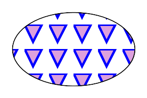
Example pattern01
interface SVGGradientElement : SVGDefinitionElement {

  // Spread Method Types
  const unsigned short SVG_SPREADMETHOD_UNKNOWN = 0;
  const unsigned short SVG_SPREADMETHOD_PAD = 1;
  const unsigned short SVG_SPREADMETHOD_REFLECT = 2;
  const unsigned short SVG_SPREADMETHOD_REPEAT = 3;

  readonly attribute SVGAnimatedEnumeration gradientUnits;
  readonly attribute SVGAnimatedTransformList gradientTransform;
  readonly attribute SVGAnimatedEnumeration spreadMethod;
};

SVGGradientElement implements SVGURIReference;
SVGGradientElement implements SVGUnitTypes;
interface SVGLinearGradientElement : SVGGradientElement {
  readonly attribute SVGAnimatedLength x1;
  readonly attribute SVGAnimatedLength y1;
  readonly attribute SVGAnimatedLength x2;
  readonly attribute SVGAnimatedLength y2;
};interface SVGRadialGradientElement : SVGGradientElement {
readonly attribute SVGAnimatedLength cx;
readonly attribute SVGAnimatedLength cy;
readonly attribute SVGAnimatedLength r;
readonly attribute SVGAnimatedLength fx;
readonly attribute SVGAnimatedLength fy;
readonly attribute SVGAnimatedLength fr;
};interface SVGMeshGradientElement : SVGGradientElement {
readonly attribute SVGAnimatedLength x;
readonly attribute SVGAnimatedLength y;
};interface SVGMeshRowElement : SVGElement {
};
interface SVGMeshPatchElement : SVGElement {
};
interface SVGStopElement : SVGElement {
  readonly attribute SVGAnimatedNumber offset;
};interface SVGPatternElement : SVGDefinitionElement {
readonly attribute SVGAnimatedEnumeration patternUnits;
readonly attribute SVGAnimatedEnumeration patternContentUnits;
readonly attribute SVGAnimatedTransformList patternTransform;
readonly attribute SVGAnimatedLength x;
readonly attribute SVGAnimatedLength y;
readonly attribute SVGAnimatedLength width;
readonly attribute SVGAnimatedLength height;
};
SVGPatternElement implements SVGFitToViewBox;
SVGPatternElement implements SVGURIReference;
SVGPatternElement implements SVGUnitTypes;