This Working Draft specifies version 1.2 of the Scalable
Vector Graphics (SVG) Language, a modularized language for
describing two-dimensional vector and mixed vector/raster
graphics in XML
This document is the first public working draft of this
specification. It lists the potential areas of new work in
version 1.2 of SVG and is not a complete language description.
In most cases, the descriptions in this document are incomplete
and simply show the current thoughts of the SVG Working Group
on the feature. This document should in no way be considered
stable. This version does not include the
implementations of SVG 1.2 in either DTD or XML Schema form.
Those will be included in subsequent versions, once the
contents of this language stabilizes.
Publication of this document does not imply endorsement by
the W3C membership. A list of current W3C Recommendations and
other technical documents can be found at http://www.w3.org/TR/. W3C
publications may be updated, replaced, or obsoleted by other
documents at any time. It is inappropriate to cite a W3C
Working Draft as anything other than a "work in
progress."
SVG 1.2 enables a block of text to be rendered inside a
shape, while automatically wrapping the text into lines,
using the flowText element. The
idea is to mirror, as far as possible, the existing SVG text
elements.
1.1 The flowText element
The flowText element
specifies a block of text to be rendered. It contains a flowLayout element that defines
regions in which the child flowDiv element of the flowText should be laid out flowed
into.
The following is a extract of an XML Schema that described
the flowText element.
<xs:element name="flowText">
  <xs:complexType>
    <xs:sequence>
      <xs:element ref="flowLayout"/>
      <xs:element ref="flowDiv"/>
    </xs:sequence>
    <xs:attributeGroup ref="PresentationAttrs"/>
    <xs:attributeGroup ref="StyleAttrs"/>
  </xs:complexType>
</xs:element>
1.2 The flowLayout element
The flowLayout element
contains a set of shapes in which the text content of a
parent flowText element is to be
laid out. The children of a flowLayout element are flowRegion elements.
The flowLayout element and
its children are never rendered.
The following is a extract of an XML Schema that described
the flowLayout element.
<xs:element name="flowLayout">
  <xs:complexType>
    <xs:sequence>
      <xs:element ref="flowRegion" minOccurs="0" maxOccurs="unbounded"/>
    </xs:sequence>
  </xs:complexType>
</xs:element>
1.3 The flowRegion element
The flowRegion element can
define a rectangular region in the current user coordinate
system through it's x, y, width, and height attributes, or it may
reference existing geometry through it's xlink:href attribute.
When used the xlink:href
must directly reference path,
text, or basic shape elements.
Indirect references are an error.
The following is a extract of an XML Schema that described
the flowtext element.
<xs:element name="flowRegion">
  <xs:complexType>
    <xs:attribute ref="xlink:href"/>
    <xs:attribute name="x"/>
    <xs:attribute name="y"/>
    <xs:attribute name="width"/>
    <xs:attribute name="height"/>
  </xs:complexType>
</xs:element>
The margin properties behave as described in the CSS 2
specification Section 8.3. When percentage units are used
they are percentages of the bounding box of the view
port.
1.4 The flowDiv element
The flowDiv element specifies
a block of text to be inserted into the text layout, and
marks it as a division of related text. The children of the
flowDiv element will be rendered
as a block: offset before and after from their parent's
siblings. By separating the logical order of text (in
successive flowDiv elements) from the physical layout (in
regions, which can be presented anywhere on the canvas) the
SVG document structure encourages creation of a default,
meaningful linear reading order while preserving artistic
freedom for layout. This enhances accessibility.
The following is a extract of an XML Schema that described
the flowtext element.
<xs:element name="flowDiv">
  <xs:complexType>
    <xs:choice minOccurs="0" maxOccurs="unbounded">
      <xs:element ref="flowPara"/>
      <xs:element ref="flowRegionBreak"/>
    </xs:choice>
    <xs:attributeGroup ref="PresentationAttrs"/>
    <xs:attributeGroup ref="StyleAttrs"/>
  </xs:complexType>
</xs:element>
The space-before, space-after properties behave as
described in the XSL specification sections 7.10.5 &
6.
1.5 The flowPara element
The flowPara element marks a
block of text as a logical paragraph. The children of the
flowPara element will be
rendered as a block: offset before and after from their
parent's siblings.
The following is a extract of an XML Schema that described
the flowPara element.
<xs:element name="flowPara">
  <xs:complexType mixed="true">
    <xs:choice minOccurs="0" maxOccurs="unbounded">
      <xs:element ref="flowRegionBreak"/>
      <xs:element ref="flowLine"/>
      <xs:element ref="flowTref"/>
      <xs:element ref="flowSpan"/>
    </xs:choice>
    <xs:attributeGroup ref="PresentationAttrs"/>
    <xs:attributeGroup ref="StyleAttrs"/>
  </xs:complexType>
</xs:element>
The 'space-before', 'space-after' properties behave as
described in the XSL specification sections 7.10.5 &
6.
'text-index' behaves as described in the CSS 2
specification. SVG viewers are required to support negative
values for text-indent.
'text-align' behaves as described in the CSS 2
specification Section 16.2. As per the CSS specification SVG
viewers are not required to implement the value 'justify'
except by mapping it to 'left' or 'right' as the CSS
Specification suggests. Authors should be aware that use of
'justify' may lead to implementation specific behaviour.
'preformatted' This has the sole effect of turning off the
suppression of non-printing (white space) characters at the
start of a line.
Whether or not to have a 'preformatted'
attribute is currently in discussion.
1.6 The flowSpan element
The flowSpan element
specifies a block of text to be rendered inline, and marks
the text as a related span of words. The flowSpan element is typically used to
allow a subset of the text block, of which it is a child, to
be rendered in a different style, or to mark it as being in a
different language.
The following is a extract of an XML Schema that described
the flowSpan element.
<xs:element name="flowSpan">
  <xs:complexType mixed="true">
    <xs:choice minOccurs="0" maxOccurs="unbounded">
      <xs:element ref="flowSpan"/>
      <xs:element ref="flowLine"/>
      <xs:element ref="flowRegionBreak"/>
    </xs:choice>
    <xs:attributeGroup ref="PresentationAttrs"/>
    <xs:attributeGroup ref="StyleAttrs"/>
  </xs:complexType>
</xs:element>
1.7 The flowRegionBreak element
The flowRegionBreak element
causes the text to stop flowing into the current region and
being flowing into the next region. If there is no next
region, then the text will stop at the point of the flowRegionBreak.
The following is a extract of an XML Schema that described
the flowRegionBreak element.
<xs:element name="flowRegionBreak">
  <xs:complexType/>
</xs:element>
1.8 The flowLine element
The flowLine element is used
to force a line break in the text flow. The content following
the end of a flowLine element
will be placed on the next available strip in the flowRegion that does not already
contain text. This happens even if the flowLine element has no children.
Note that if there are no printing characters between the
end of multiple flowLine
elements the second and greater flowLine elements have no effect as
the current line does not contain any text when they are
processed.
In all other aspects, the flowLine element is functionally
equivalent to the flowSpan
element.
The following is a extract of an XML Schema that described
the flowLine element.
<xs:element name="flowLine">
  <xs:complexType mixed="true">
    <xs:choice minOccurs="0" maxOccurs="unbounded">
      <xs:element ref="flowSpan"/>
      <xs:element ref="flowLine"/>
      <xs:element ref="flowRegionBreak"/>
    </xs:choice>
    <xs:attributeGroup ref="PresentationAttrs"/>
    <xs:attributeGroup ref="StyleAttrs"/>
  </xs:complexType>
</xs:element>
1.9 The flowTref element
The flowTref element is used
to insert the child text content of a referenced element.
It's effect is analogous to the tref element.
The following is a extract of an XML Schema that described
the flowTref element.
<xs:element name="flowTref">
  <xs:complexType>
    <xs:attribute ref="href" use="required"
        namespace="http://www.w3.org/1999/xlink"/>
    <xs:attributeGroup ref="PresentationAttrs"/>
    <xs:attributeGroup ref="StyleAttrs"/>
  </xs:complexType>
</xs:element>
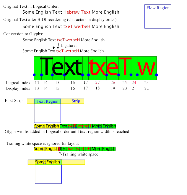
1.10 Text Flow
Text Flow is defined as a post processing step to the standard
text layout model of SVG. This allows implementations to
preserve existing code for text layout.
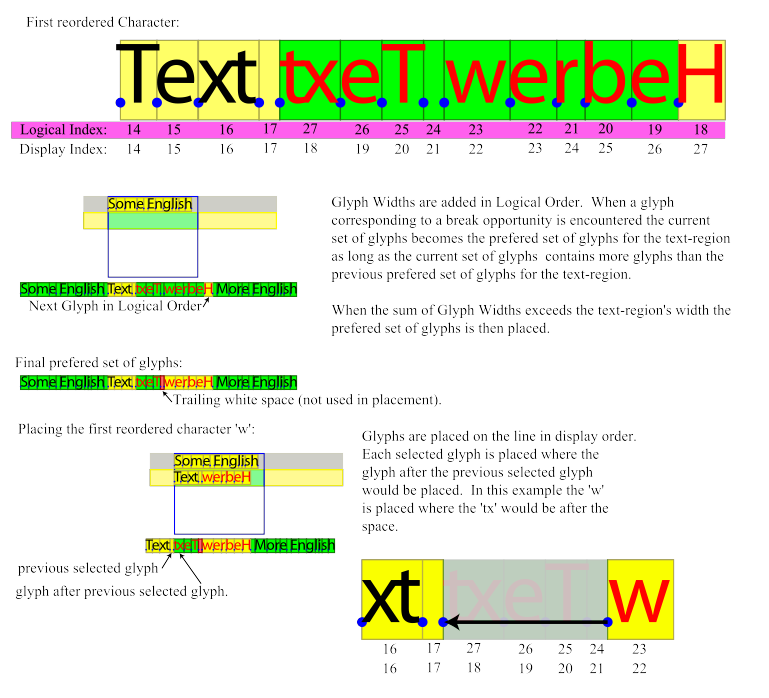
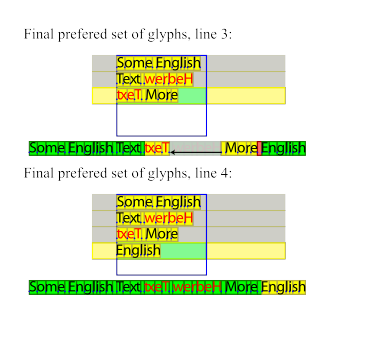
At a very high level this algorithm works by identifying word
breaks in the original text using Unicode Standard Annex #14.
Then the glyphs corresponding to words are taken in logical
order and placed, in display order, on the current line (which
may have several text regions). When the next word can not
fit on the current line the algorithm moves to the next line,
and calculates a new set of regions for text placement.
- Text layout is performed as normal, on one infinitely
long line. The result is a set of positioned Glyphs.
- The text is then processed in logical order to
determine line breaking opportunities between characters,
according to Unicode Standard Annex #14
(http://www.unicode.org/unicode/reports/tr14)
- The flow region is examined to determine the
available width of the first strip's, first text
region.
-
For each character in the text in logical order
- Get the glyph associated with the current
character.
- If the current glyph has been placed already
(ligatures) skip to the next char.
-
If the current glyph is a printing character and
will not fit on the line, then store the best line
layout for this text region in the list of line
layouts for this strip. If the updated list of line
layouts is better than the best list of line
layouts for the strip (based on number of
characters) then it becomes the best list of line
layouts for the strip.
Processing backs up to the first character/glyph
after the best line layout.
Then iterate through the remaining text regions
for this strip until one is found of sufficient
width to hold the next glyph [word?] at which point
processing continues.
If no such text region is found then:
- Add the best list of line layouts for this
strip to to the list of line layouts for the
flow.
- Processing backs up to the first
character/glyph after the last line layout in the
best list of line layouts for this strip.
- Then construct a new strip based and
corresponding text regions.
- If no new strip can be constructed (out of
room in flow regions) then the current and all
following glyphs are hidden and text layout
stops.
-
If the current glyph changes the height of the
line-box (usually due to a change in font-size)
- Add the best line layout for this text region
to the list of line layouts for this strip. If
the updated list of line layouts for this strip
is better than the best list of line layouts for
the strip (based on number of characters) then it
becomes the new best list of line layouts for the
strip.
- Recalculate the strip and corresponding text
regions. Then go back to the first
character/glyph for this strip and start laying
out text again.
- The current glyph is marked for inclusion in the
current line layout.
- While the next char in the text (logical order)
maps to the current glyph go to the next char (i.e.
get to last char in a ligature). [ Should we do
this??? ]
-
If the current line layout is better than the
current best line layout for this text region,
replace it.
A line layout (A) is considered better than
another line layout (B), if A contains more
characters than B, and if B ends with a break
opportunity A must also end in a break
opportunity.
A Soft Hyphen can only be considered a break
opportunity if the hyphen will fit.
- Loop and handle next character in text.
-
For each Line layout in the list of line layouts
- Collapse the glyphs marked for inclusion on the
current text region from the infinitely long
line.
- Apply the text-align property.
The SVG Working Group actively encourages feedback on this algorithm, especially in relation to bidirectional text.
The following diagrams illustrate the above algorithm. Note
that an SVG version of this
diagram is available. This rasterization probably obscures the
text on most displays.
 (View the above diagrams in SVG)
1.11 Calculating Strips and Text Regions
In order to flow text into arbitrary regions it is
necessary to calculate what portions of the object are
available for text. SVG uses a fairly simple algorithm to do
this. In summary you intersect the flow Region with the an
infinitely wide line-box referred to below as the 'strip'.
The result is then split into text regions where ever an edge
from the flow region 'intrudes' into the line box.
The location and height of the line box must be provided,
this is done for the first line by the 'first-line fitting
alg' and subsequent lines follow the rules for inline
formatting contexts (line-boxes stack).
Once the location of the line box in non-text progression
direction is calculated the flow region is intersected by
that line box clipping the segments of the path to the line
box.
The bounding box is calculated for each of the clipped
path segments. The left and right edges of the bounding boxes
are sorted in order of increasing x (for equal x's left edges
are considered less than right edges). The following pseudo
code then generates the list of open areas for the current
line.
        float start = 0;
        int   count = 1;

        // Skip the first edge since it must be a left edge.
        for (int i=1; i<numEdges; i++) {
          if (edges[i].side == LEFT)  {
            // Left edge of BBox.
            if (count == 0) {
              // End of an open region so record it.
              rgns.add(new LineBox(start, edges[i].loc));
            }
            ++count;
          } else {
            // Right edge of a BBox.
            --count;
            if (count == 0) {
              // Start of an 'open area' remember it.
              start = edges[i].loc;
            }
          }
        }
This gives the regions of the strip that are unobstructed
by flow region geometry, however those regions may be outside
the flow region (such as in a hole, such as the middle of an
'O'). So the center of each rectangle should be checked to
ensure it lies within the bounds of the flow region's
geometry.
The final result is a list of regions available for the
placement of text for that particular strip, these are called
the 'text regions' for the strip. Note that for complex
shapes there may be several text regions for a single
strip.
All the text regions from a single strip are used before
another strip is considered.
After the text regions are calculated the text-indent
attribute is applied to the text-region if appropriate.
A number of relevant XML formats have matured since the
time of the SVG 1.0 Recommendation. It is the intent of the
SVG Working Group to allow easy integration with these
formats, as well as to be a display format for generic
XML.
XForms [XForms] is a technology for describing forms in XML.
It separates the model or content of the form from its
presentation and is designed to be integrated into a host
language, such as SVG. This provides the host language with
an abstract definition of form content and leaves the
rendering to the host. SVG is well suited to hosting
XForms, since it provides powerful rendering and
interactivity APIs.
Furthermore, a generic set of user interface components
has been a common request from the SVG community. By
describing how SVG and XForms can be integrated that
request can be answered while providing more functionality
if required. For example, the tight integration with a data
model of a form should allow an SVG/XForms implementation
to package SOAP messages easily. It also would allow an
author to provide multiple interfaces to the same form
(SVG, CSS, VoiceXML).
It also should be possible to extend generic form
controls to use an SVG rendering specified by the document
author. Events within the SVG rendering should be linked to
behavior that updates the form model.
At the time of publication, the Working
Group is undecided as to whether or not the SVG
specification should describe a default rendering and
behavior for some form elements, such as buttons and
sliders. We realise that creating widget sets is a deep
topic and specifically request feedback on this matter.
Would a simple set of form widgets be sufficient in most
situations, or would authors prefer to always create the
SVG rendering and behaviour for every element?
XML Events [XMLEvents] is an XML syntax for integrating event
listeners with DOM Event handlers. The events in SVG are
hardwired into the language, such that you are required to
embed the specification of event handling within the
content (e.g. an element has an onclick attribute). By
allowing XML Events, SVG content can specify the event
listeners separately from the graphical content.
The specifics of what is meant by "allowing
XML Events" is not yet clear. It may be that all event
attributes from SVG 1.0/1.1 are deprecated in favor of XML
events. Also, conformance has not yet been discussed -
should all SVG viewers be required to support XML
Events?
SVG 1.0 included SMIL Animation for its animation
syntax. It has been a common request from the public to
have more features from SMIL in SVG. For that reason, SVG
1.2 will mostly likely incorporate more of SMIL, such as
audio, video, transitions and enhanced timing controls.
The SVG Working Group may produce a W3C
Note which defines an SVG+SMIL profile, similar to the
XHTML+SMIL profile [XHTML+SMIL]. Alternatively, SVG could include
more of the SMIL elements within the SVG namespace (e.g.
the par, seq, audio and video elements).
SVG would probably not include SMIL
Layout, Linking, Structure and MetaInformation. SVG might
include parts of SMIL Media (audio and video), Content
Control (test attributes related to Media), Timing and
Synchronization (par, seq, excl elements as well as
synchronization attributes). Time manipulation and
transitions may be optional.
Many of the enhancements to the SVG language are based
on using SVG as a presentation layer for structured data
(e.g. XForms). Public feedback has also suggested that many
content developers are using SVG as the graphical user
interface to their XML data, either through declarative
transformations such as XSLT or through scripting (loading
XML data into the SVG User Agent and transforming using the
DOM).
The SVG Working Group is examining this use case
closely, to see if there is anything that can be added to
SVG in order to better facilitate this technique. While it
is already possible today to use scripting to transform XML
from a private namespace into SVG, the code has to be
replicated in each SVG file and modified for each
namespace. It may be possible to provide more support for a
declarative syntax, similar to, or using parts of,
XSLT.
The Working Group has not reached a
conclusion on the requirements for such a feature. Should
the mapping be one way or two way (ie. should there be a
way to automatically reflect changes in the transformed
content when the transformation is updated?) Should the
feature be enabled by the styling system (ie. should you be
able to apply a style rule that converts all myns:pie
elements into a combination of svg:path elements?) Is this
an extension to the 'use' element?
Again, a goal is to facilitate including
semantically-rich XML content within the SVG file while
having the SVG viewer render the XML. The user only need
understand the XML and need not be concerned with the more
complicated SVG content.
If a declarative syntax is used, SVG
implementations may be required to support XPath and some
simple XSLT features.
The SVG Working Group are considering a number of
modifications to the rendering model for SVG 1.2. As the
rendering model is perhaps the most important concept in the
graphical representation of SVG content, any change to the
model has to both fulfill a strong requirement and to be
extremely carefully checked in order to not introduce
inconsistencies, break existing content or have a substantial
negative effect on implementations.
SVG 1.0 uses a simple rendering model, the Painter's
Model, where a graphical object is composited onto the
canvas above the objects that came before it in the
document. While there is the ability to allow enhanced
compositing within the filter system, there is no way to
remove painting operations once they have been composited
to the canvas. There are some usage scenarios where it
would be advantageous to allow the enhanced compositing
operations inline (ie. outside of the SVG 1.0 filter
mechanism) since it may allow an implementation to perform
the operation without rasterization. When placing graphical
objects on the canvas, the result will be dependent on
input color and opacity, the existing color and opacity on
the canvas and the compositing operation. This will allow
objects to remove "paint" from the canvas.
The actual technique that would allow such
a feature is still under discussion. We propose three
alternatives here, but make no guarantee that we will chose
one. We strongly request feedback from the public
on this feature.
The compositing operations under consideration are the 12
Porter-Duff operations [PORTERDUFF], 5 of which are
implemented in the 'feComposite' element, the blending
operations implemented by the 'feBlend' element and possibly a
number of other operations (e.g. lightening colors, producing
the color difference between the composited images). Other
features under consideration are "Clip to Self" which
restricts the compositing operation to the bounds of the
graphical object, a behaviour common in the Java2D imaging
model, and "Knockout Groups", the ability to remove parts of
an object from rendering.
Repeating what was said above, modifications to the
rendering model need to be carefully examined. Operations
that may work well for simple objects may not map easily
to complicated groups of objects. The SVG Working Group
will attempt to meet at least the following
requirements:
- Continuity: Small changes in parameters for
compositing lead to small changes in the final visual
result.
- Treat a group as an object: Any operation that can
be done to a single element can be done to a group, and
visa-versa.
Below are three alternatives for enhanced compositing.
By adding an attribute, 'comp-op' to each rendering element
(ie. the graphical elements plus the grouping elements) it
would be possible to describe inline compositing operations.
<svg>
  <rect x="10" y="10" width="30" height="30" fill="blue"/>
  <rect x="20" y="20" width="30" height="30" fill="red"
     fill-opacity="0.5" comp-op="src-in"/>
  <g comp-op="multiply" opacity="0.7">
    <rect x="30" y="30" width="30" height="30" fill="green"/>
    <rect x="40" y="40" width="30" height="30" fill="red"/>
  </g>
</svg>
The 'painters model' from SVG 1.0 is easily optimized. Since
enhanced compositing is such a variation on the SVG 1.0
model, it may be better to define a special grouping
operator that enables the richer compositing model. Only the
elements of the 'composite' group are able to be composited
in a manner other than directly on their background.
The SVG 1.0 language provides most of the required
compositing operations, but does it through the filter model
rather than allowing inline compositing. It may be possible
to come up with a solution that allows a restricted set of
filters to be placed inline with the rest of the SVG content
(as opposed to referencing a predefined filter element when
rendering an object).
<svg enable-background="new">
  <!-- whatever -->
  <feComposite op="src" x= y= width= height=>
    <defs>
      <path id="p" .../>
    </defs>
    <feGaussianBlur r=... >
      <feOffset dx= dy= >
        <use xlink:href="#p">
      </feOffset>
    </feGaussianBlur>
    <use xlink:href="#p">
    <text.../>
  </feComposite>
</svg>
There have been a number of requests to provide a
mechanism that separates drawing order from document order,
a feature commonly referred to as "Z index". The SVG Working
Group is evaluating the need for the feature as well as
several possible solutions.
It is possible to simulate such a feature at the moment
either using SMIL animation and multiple 'use' elements, or
through scripting (moving an element toward the end of the
document). However, both can place restrictions on document
structure, and have limitations in the area of property inheritance.
The SVG Working Group requests feedback on
this feature, especially any specific requirements you may
have. SVG 1.2 plans to enable a drawing order independent
of document order, a feature commonly referred to as Z
index. This feature is in very early development - there
are no further details at the moment.