7 Coordinate Systems, Transformations and Units
Contents
7.1 Introduction
For all media, the canvas
describes "the space where the SVG content is rendered." The
canvas is
infinite for each dimension of the space, but rendering occurs relative to a
finite rectangular region of the
canvas. This
finite rectangular region is called the SVG
viewport.
For visual
media ([CSS2], section 7.3.1), the SVG
viewport
is the viewing area where the user sees the SVG content.
The size of the SVG
viewport
(i.e., its width and height) is determined by a negotiation process (see
Establishing the size of the initial viewport)
between the SVG document fragment and its parent (real or implicit).
Once the viewport
is established, the
SVG user agent
must establish the initial
viewport
coordinate system and the initial
user
coordinate system (see
Initial coordinate system).
The viewport
coordinate system is also called viewport space
and the user coordinate system is also called
user space.
A new user space
(i.e., a new current coordinate system) can be established at any place within
an SVG document fragment by specifying
transformations
in the form of
transformation matrices
or simple transformation operations such as rotation, skewing, scaling and translation
(see Coordinate system transformations).
Establishing new user spaces via coordinate
system transformations are fundamental operations to 2D graphics and
represent the usual method of controlling the size, position, rotation and
skew of graphic objects.
New viewports also can be established. By
establishing a new viewport, one can
provide a new reference rectangle for "fitting" a graphic into a particular
rectangular area. ("Fit" means that a given graphic is transformed in such a
way that its bounding box
in user space aligns exactly with the edges of a given
viewport.)
7.2 The initial viewport
The SVG user agent
negotiates with its parent
user agent
to determine the viewport
into which the SVG user agent
can render the document. In some circumstances, SVG content will be embedded
(by reference or inline) within a
containing document. This containing document might include attributes,
properties and/or other parameters (explicit or implicit) which specify or
provide hints about the dimensions of the
viewport
for the SVG content. SVG content itself optionally can provide information
about the appropriate viewport
region for the content via the
'width'
and 'height'
XML attributes on the 'svg'
element. The negotiation process uses any information provided by the
containing document and the SVG content itself to choose the
viewport
location and size.
If the parent document format defines rules for referenced or embedded
graphics content, then the negotiation process is determined by the parent
document format specification. If the parent document is styled with CSS,
then the negotiation process must follow the CSS rules for replaced elements.
If there are CSS width and height properties (or corresponding XSL properties)
on the referencing element (or
rootmost 'svg' element
for inline SVG content) that are sufficient to establish the width and height
of the viewport,
then these positioning properties establish the viewport's
width, height, and aspect ratio.
If there is no parent document, the SVG user agent must use the
'width' and
'height' attributes
on the rootmost 'svg' element
element as the width and height for the
viewport.
Note that the time at which the viewport size negotiation is finalized
is implementation-specific. Authors who need to be sure of the dimensions
of the viewport should do so with
load-event or
resize-event handlers.
7.3 The initial coordinate system
For the 'svg'
element, the SVG
user agent must establish an initial
viewport
coordinate system and an initial
user
coordinate system such that the two coordinates systems are
identical. The origin of both coordinate systems must be at the origin of the
viewport,
and one unit in the initial coordinate system must equal one "pixel" (i.e.,
a
px unit as defined in CSS ([CSS2],
section 4.3.2)) in the
viewport.
In most cases, such as stand-alone SVG documents or
SVG document fragments
embedded (by reference or inline)
within XML parent documents where the parent's layout is determined by CSS
[CSS2] or XSL
[XSL], the
SVG user agent
must establish the initial
viewport
coordinate system (and therefore the initial
user coordinate system)
such that its origin is at the top/left of the
viewport,
with the positive x-axis pointing towards the right, the positive y-axis
pointing down, and text rendered with an "upright" orientation, which means
glyphs are oriented such that Roman characters and full-size ideographic
characters for Asian scripts have the top edge of the corresponding glyphs
oriented upwards and the right edge of the corresponding glyphs oriented
to the right.
If the SVG implementation is part of a
user agent
which supports styling XML documents using CSS2-compatible
px units, then the
SVG user agent
should get its initial value for the size of a px unit in real world
units to match the value used for other XML styling operations;
otherwise, if the user agent
can determine the size of a px unit from its environment, it should
use that value; otherwise, it should choose an appropriate size for one
px unit. In all cases, the size of a px must be in
conformance with the
rules
described in CSS ([CSS2], section 4.3.2).
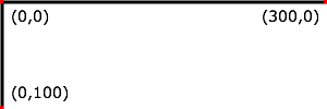
Example 07_02 below shows that the initial
coordinate system has the origin at the top/left with the x-axis pointing to
the right and the y-axis pointing down. The initial user coordinate system has
one user unit equal to the parent (implicit or explicit)
user agent's
"pixel".
<?xml version="1.0"?>
<svg xmlns="http://www.w3.org/2000/svg" version="1.2" baseProfile="tiny"
     width="300px" height="100px">

  <desc>Example InitialCoords - SVG's initial coordinate system</desc>

  <g fill="none" stroke="black" stroke-width="3">
    <line x1="0" y1="1.5" x2="300" y2="1.5"/>
    <line x1="1.5" y1="0" x2="1.5" y2="100"/>
  </g>
  <g fill="red" stroke="none">
    <rect x="0" y="0" width="3" height="3"/>
    <rect x="297" y="0" width="3" height="3"/>
    <rect x="0" y="97" width="3" height="3"/>
  </g>
  <g font-size="14" font-family="Verdana">
    <text x="10" y="20">(0,0)</text>
    <text x="240" y="20">(300,0)</text>
    <text x="10" y="90">(0,100)</text>
  </g>
</svg>
7.4 Coordinate system transformations
A new user space
(i.e., a new current coordinate system) can be established by specifying
transformations
in the form of a 'transform'
attribute on a
container
or graphics element,
or a 'viewBox'
attribute on the 'svg'
element. The 'transform'
and 'viewBox'
attributes transform user space coordinates and lengths on sibling attributes
on the given element (see
effect of the
'transform' attribute on sibling attributes
and effect of
the 'viewBox' attribute on sibling
attributes) and all of its descendants. Transformations can be nested,
in which case the effect of the transformations are cumulative.
Example 07_03 below shows a document without
transformations. The text string is specified in the
initial coordinate system.
<?xml version="1.0"?>
<svg xmlns="http://www.w3.org/2000/svg" version="1.2" baseProfile="tiny"
     width="400px" height="150px">

  <desc>Example OrigCoordSys - Simple transformations: original picture</desc>

  <g fill="none" stroke="black" stroke-width="3">
    <!-- Draw the axes of the original coordinate system -->
    <line x1="0" y1="1.5" x2="400" y2="1.5"/>
    <line x1="1.5" y1="0" x2="1.5" y2="150"/>
  </g>
  <g>
    <text x="30" y="30" font-size="20" font-family="Verdana">
      ABC (orig coord system)
    </text>
  </g>
</svg>
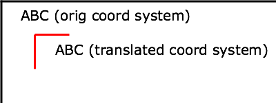
Example 07_04 establishes a new
user coordinate system
by specifying transform="translate(50,50)" on
the third 'g'
element below. The new user coordinate system has its origin at location
(50,50) in the original coordinate system. The result of this
transformation is that the coordinate (30,30) in the new
user coordinate system gets mapped to coordinate (80,80) in the
original coordinate system (i.e., the coordinates have been
translated by 50 units in x and 50 units in y).
<?xml version="1.0"?>
<svg xmlns="http://www.w3.org/2000/svg" version="1.2" baseProfile="tiny"
     width="400px" height="150px">

  <desc>Example NewCoordSys - New user coordinate system</desc>

  <g fill="none" stroke="black" stroke-width="3">
    <!-- Draw the axes of the original coordinate system -->
    <line x1="0" y1="1.5" x2="400" y2="1.5"/>
    <line x1="1.5" y1="0" x2="1.5" y2="150"/>
  </g>
  <g>
    <text x="30" y="30" font-size="20" font-family="Verdana">
      ABC (orig coord system)
    </text>
  </g>
  <!-- Establish a new coordinate system, which is
       shifted (i.e., translated) from the initial coordinate
       system by 50 user units along each axis. -->
  <g transform="translate(50,50)">
    <g fill="none" stroke="red" stroke-width="3">
      <!-- Draw lines of length 50 user units along
           the axes of the new coordinate system -->
      <line x1="0" y1="0" x2="50" y2="0" stroke="red"/>
      <line x1="0" y1="0" x2="0" y2="50"/>
    </g>
    <text x="30" y="30" font-size="20" font-family="Verdana">
      ABC (translated coord system)
    </text>
  </g>
</svg>
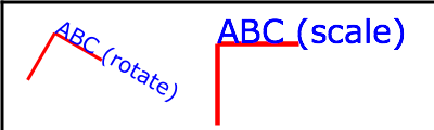
Example 07_05 illustrates simple
rotate and scale transformations. The
example defines two new coordinate systems:
- one which is the result of a translation by 50 units in x
and 30 units in y, followed by a rotation of 30 degrees
- another which is the result of a translation by 200 units
in x and 40 units in y, followed by a scale
transformation of 1.5.
<?xml version="1.0"?>
<svg xmlns="http://www.w3.org/2000/svg" version="1.2" baseProfile="tiny"
     width="400px" height="120px">

  <desc>Example RotateScale - Rotate and scale transforms</desc>

  <g fill="none" stroke="black" stroke-width="3">
    <!-- Draw the axes of the original coordinate system -->
    <line x1="0" y1="1.5" x2="400" y2="1.5"/>
    <line x1="1.5" y1="0" x2="1.5" y2="120"/>
  </g>
  <!-- Establish a new coordinate system whose origin is at (50,30)
       in the initial coord. system and which is rotated by 30 degrees. -->
  <g transform="translate(50,30)">
    <g transform="rotate(30)">
      <g fill="none" stroke="red" stroke-width="3">
        <line x1="0" y1="0" x2="50" y2="0"/>
        <line x1="0" y1="0" x2="0" y2="50"/>
      </g>
      <text x="0" y="0" font-size="20" font-family="Verdana" fill="blue">
        ABC (rotate)
      </text>
    </g>
  </g>
  <!-- Establish a new coordinate system whose origin is at (200,40)
       in the initial coord. system and which is scaled by 1.5. -->
  <g transform="translate(200,40)">
    <g transform="scale(1.5)">
      <g fill="none" stroke="red" stroke-width="3">
        <line x1="0" y1="0" x2="50" y2="0"/>
        <line x1="0" y1="0" x2="0" y2="50"/>
      </g>
      <text x="0" y="0" font-size="20" font-family="Verdana" fill="blue">
        ABC (scale)
      </text>
    </g>
  </g>
</svg>
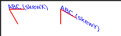
Example 07_06 defines two coordinate systems
which are skewed relative to the origin coordinate system.
<?xml version="1.0"?>
<svg xmlns="http://www.w3.org/2000/svg" version="1.2" baseProfile="tiny"
     width="400px" height="120px">

  <desc>Example Skew - Show effects of skewX and skewY</desc>

  <g fill="none" stroke="black" stroke-width="3">
    <!-- Draw the axes of the original coordinate system -->
    <line x1="0" y1="1.5" x2="400" y2="1.5"/>
    <line x1="1.5" y1="0" x2="1.5" y2="120"/>
  </g>
  <!-- Establish a new coordinate system whose origin is at (30,30)
       in the initial coord. system and which is skewed in X by 30 degrees. -->
  <g transform="translate(30,30)">
    <g transform="skewX(30)">
      <g fill="none" stroke="red" stroke-width="3">
        <line x1="0" y1="0" x2="50" y2="0"/>
        <line x1="0" y1="0" x2="0" y2="50"/>
      </g>
      <text x="0" y="0" font-size="20" font-family="Verdana" fill="blue">
        ABC (skewX)
      </text>
    </g>
  </g>
  <!-- Establish a new coordinate system whose origin is at (200,30)
       in the initial coord. system and which is skewed in Y by 30 degrees. -->
  <g transform="translate(200,30)">
    <g transform="skewY(30)">
      <g fill="none" stroke="red" stroke-width="3">
        <line x1="0" y1="0" x2="50" y2="0"/>
        <line x1="0" y1="0" x2="0" y2="50"/>
      </g>
      <text x="0" y="0" font-size="20" font-family="Verdana" fill="blue">
        ABC (skewY)
      </text>
    </g>
  </g>
</svg>
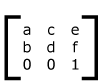
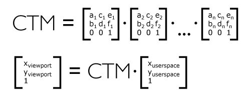
Mathematically, all transformations can be represented as 3x3
transformation matrices
of the following form:
Since only six values are used in the above 3x3 matrix, a
transformation matrix
is also expressed as a vector:
[a b c d e f].
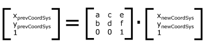
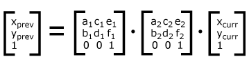
Transformations map coordinates and lengths from a new coordinate system
into a previous coordinate system:
Simple transformations are represented in matrix form as follows:
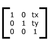
-
Translation is equivalent to the matrix:
or [1 0 0 1 tx ty], where tx and
ty are the distances to translate coordinates in
x and y, respectively.
-
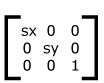
Scaling is equivalent to the matrix:
or [sx 0 0 sy 0 0]. One unit in the
x and y directions in the new coordinate
system equals sx and sy units in the
previous coordinate system, respectively.
-
Rotation about the origin is equivalent to the matrix:
or [cos(a) sin(a) -sin(a) cos(a) 0 0],
which has the effect of rotating the coordinate system axes
by angle a.
-
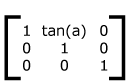
A skew transformation along the x-axis is equivalent to the
matrix:
or [1 0 tan(a) 1 0 0], which has the effect of skewing
x coordinates by angle a.
-
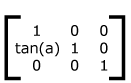
A skew transformation along the y-axis is equivalent to the
matrix:
or [1 tan(a) 0 1 0 0], which has the effect
of skewing y coordinates by angle a.
Transformations can be nested to any level. The effect of
nested transformations is to post-multiply (i.e., concatenate)
the subsequent transformation matrices onto previously defined
transformations:
For each given element, the accumulation of all
transformations that have been defined on the given element and
all of its ancestors up to and including the element that
established the current
viewport
(usually, the 'svg'
element which is the most immediate ancestor to the given element) is called
the current
transformation matrix or
CTM.
The CTM
thus represents the mapping of current user coordinates to viewport
coordinates:
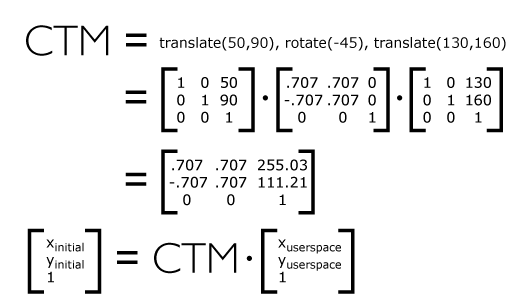
Example 07_07 illustrates nested
transformations.
<?xml version="1.0"?>
<svg width="400px" height="150px" version="1.2" baseProfile="tiny"
     xmlns="http://www.w3.org/2000/svg">
  <desc>Example Nested - Nested transformations</desc>
  <g fill="none" stroke="black" stroke-width="3" >
    <!-- Draw the axes of the original coordinate system -->
    <line x1="0" y1="1.5" x2="400" y2="1.5" />
    <line x1="1.5" y1="0" x2="1.5" y2="150" />
  </g>
  <!-- First, a translate -->
  <g transform="translate(50,90)">
    <g fill="none" stroke="red" stroke-width="3" >
      <line x1="0" y1="0" x2="50" y2="0" />
      <line x1="0" y1="0" x2="0" y2="50" />
    </g>
    <text x="0" y="0" font-size="16" font-family="Verdana" >
      ....Translate(1)
    </text>
    <!-- Second, a rotate -->
    <g transform="rotate(-45)">
      <g fill="none" stroke="green" stroke-width="3" >
        <line x1="0" y1="0" x2="50" y2="0" />
        <line x1="0" y1="0" x2="0" y2="50" />
      </g>
      <text x="0" y="0" font-size="16" font-family="Verdana" >
        ....Rotate(2)
      </text>
      <!-- Third, another translate -->
      <g transform="translate(130,160)">
        <g fill="none" stroke="blue" stroke-width="3" >
          <line x1="0" y1="0" x2="50" y2="0" />
          <line x1="0" y1="0" x2="0" y2="50" />
        </g>
        <text x="0" y="0" font-size="16" font-family="Verdana" >
          ....Translate(3)
        </text>
      </g>
    </g>
  </g>
</svg>
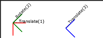
In the example above, the
CTM
within the third nested transformation (i.e., the
transform="translate(130,160)") consists of
the concatenation of the three transformations, as follows:
Attribute definition:
-
transform =
"<transform-list>"
| "<transform-ref>" | "none"
-
This attribute specifies a coordinate system transformation to apply to
the element it appears on. The value of this attribute takes one of
three forms:
- <transform-list>
-
Specifies a list of affine transformations. See the definition in
The TransformList value section below
for details.
- <transform-ref>
-
Specifies a constrained transformation. See the definition in
The TransformRef value section below
for details.
- none
-
Specifies the identity transformation. Using this value has the same
effect on the element's
CTM
as using the identity matrix (transform="matrix(1 0 0 1 0 0)")
or not specifying the 'transform'
attribute at all. This is the lacuna value.
Animatable: yes.
If the 'transform'
attribute cannot be parsed according to the syntaxes above, then it has an
unsupported value.
In this case, as with any instance of an
unsupported value,
the SVG user agent
must process the element as if the
'transform'
attribute had not been specified, which will result in the element's
transformation being the identity transformation.
A <transform-list> is defined as a
list of transform definitions, which are applied in the order
provided. The individual transform definitions are separated by
white space and/or a comma. The available types of transform
definitions are as follows:
-
matrix(<a> <b> <c> <d> <e> <f>),
which specifies a transformation in the form of a
transformation matrix of
six values. matrix(a,b,c,d,e,f) is
equivalent to applying the transformation matrix
[a b c d e f].
-
translate(<tx> [<ty>]), which
specifies a translation by
tx and ty. If <ty> is not provided,
it is assumed to be zero.
-
scale(<sx> [<sy>]), which
specifies a scale operation by
sx and sy. If <sy> is not
provided, it is assumed to be equal to <sx>.
-
rotate(<rotate-angle> [<cx> <cy>]),
which specifies a rotation by
<rotate-angle> degrees about
a given point.
If optional parameters <cx> and
<cy> are not supplied, the
rotation is about the origin of the current user coordinate system.
The operation corresponds to the matrix
[cos(a) sin(a) -sin(a) cos(a) 0 0].
If optional parameters <cx> and
<cy> are supplied, the rotation
is about the point (cx, cy). The operation
represents the equivalent of the following specification:
translate(<cx>, <cy>)
rotate(<rotate-angle>) translate(-<cx>, -<cy>).
-
skewX(<skew-angle>), which specifies
a skew transformation along the
x-axis.
-
skewY(<skew-angle>), which specifies
a skew transformation along the
y-axis.
All numeric values are real
<number>s.
If the list of transforms includes a matrix with all values set to zero (that
is, 'matrix(0,0,0,0,0,0)'), then rendering of
the element is disabled. Such a value is not an
unsupported value.
If a list of transforms includes more than one transform definition, then the
net effect is as if each transform had been specified separately in the order
provided. For example,
<g transform="translate(-10,-20) scale(2) rotate(45) translate(5,10)">
  <!-- graphics elements go here -->
</g>
will have the same rendering as:
<g transform="translate(-10,-20)">
  <g transform="scale(2)">
    <g transform="rotate(45)">
      <g transform="translate(5,10)">
        <!-- graphics elements go here -->
      </g>
    </g>
  </g>
</g>
The 'transform'
attribute is applied to an element before processing any other coordinate or
length values supplied for that element. In the element
<rect x="10" y="10" width="20" height="20" transform="scale(2)"/>
the 'x',
'y',
'width'
and 'height',
values are processed after the current coordinate system has been scaled
uniformly by a factor of 2 by the
'transform'
attribute. Attributes
'x',
'y',
'width'
and 'height'
(and any other attributes or properties) are treated as values in the new
user coordinate system,
not the previous user coordinate system. Thus, the above
'rect'
element is functionally equivalent to:
<g transform="scale(2)">
  <rect x="10" y="10" width="20" height="20"/>
</g>
The following is an EBNF grammar for
<transform-list> values
[EBNF]:
transform-list ::=
    wsp* transforms? wsp*
transforms ::=
    transform
    | transform comma-wsp+ transforms
transform ::=
    matrix
    | translate
    | scale
    | rotate
    | skewX
    | skewY
matrix ::=
    "matrix" wsp* "(" wsp*
       number comma-wsp
       number comma-wsp
       number comma-wsp
       number comma-wsp
       number comma-wsp
       number wsp* ")"
translate ::=
    "translate" wsp* "(" wsp* number ( comma-wsp number )? wsp* ")"
scale ::=
    "scale" wsp* "(" wsp* number ( comma-wsp number )? wsp* ")"
rotate ::=
    "rotate" wsp* "(" wsp* number ( comma-wsp number comma-wsp number )? wsp* ")"
skewX ::=
    "skewX" wsp* "(" wsp* number wsp* ")"
skewY ::=
    "skewY" wsp* "(" wsp* number wsp* ")"
number ::=
    sign? integer-constant
    | sign? floating-point-constant
comma-wsp ::=
    (wsp+ comma? wsp*) | (comma wsp*)
comma ::=
    ","
integer-constant ::=
    digit-sequence
floating-point-constant ::=
    fractional-constant exponent?
    | digit-sequence exponent
fractional-constant ::=
    digit-sequence? "." digit-sequence
    | digit-sequence "."
exponent ::=
    ( "e" | "E" ) sign? digit-sequence
sign ::=
    "+" | "-"
digit-sequence ::=
    digit
    | digit digit-sequence
digit ::=
    "0" | "1" | "2" | "3" | "4" | "5" | "6" | "7" | "8" | "9"
wsp ::=
    (#x20 | #x9 | #xD | #xA)
SVG 1.2 extends the coordinate system transformations allowed on
container elements
and graphics element
to provide a method by which graphical objects can remain fixed in the
viewport
without being scaled or rotated. Use cases include thin lines that do not
become fatter on zooming in, map symbols or icons of a constant size, and so
forth.
The following summarizes the different transforms that are applied to a
graphical object as it is rendered.
The user transform is the transformation that the
SVG user agent
positioning controls apply to the viewport coordinate system. This transform
can be considered to be applied to a group that surrounds the
'svg'
element of the document.
The SVG user agent
positioning controls consist of a translation (commonly referred to as the
"pan"), a scale (commonly referred to as the "zoom") and a rotate.
US = Matrix corresponding to the user scale  (currentScale on SVGSVGElement)
UP = Matrix corresponding to the user pan    (currentTranslate on SVGSVGElement)
UR = Matrix corresponding to the user rotate (currentRotate on SVGSVGElement)
The user transform is the product of these component transformations.
U = User transform
  = UP . US . UR
Some SVG elements, such as the
rootmost 'svg' element,
create their own viewport.
The 'viewBox'
to viewport
transformation is the transformation on an
'svg'
element that adjusts the coordinate system to take the
'viewBox'
and 'preserveAspectRatio'
attributes into account.
We use the following notation for a
'viewBox'
to viewport
transformation:
VB(svgId)
The svgId parameter is the value of the
'id' or
'xml:id'
attribute on a given 'svg'
element.
All elements in an SVG document have a transform stack. This is the
list of transforms that manipulate the coordinate system between the
element and its nearest ancestor
'svg'
element, i.e. in this specification, the root element.
We use the following notation for the element transform stack on a given element:
TS(id)
The id parameter is the value of the
'id' or
'xml:id'
attribute on a given element.
Similarly, we use the following notation for the transform defined by the
'transform'
attribute on the given element with identifier id:
Txf(id)
With the above definition, the transformation TS of an element is equal to
the product of all the transformations Txf from that element to its nearest
ancestor 'svg'.
TS(id) = Txf(id.nearestViewportElement) . [...] . Txf(id.parentElement) . Txf(id)
<svg xml:id="root" version="1.2" baseProfile="tiny">
  <g xml:id="g" transform="scale(2)">
    <rect xml:id="r" transform="scale(4)"/>
    <g xml:id="g2">
      <rect xml:id="r2" transform="scale(0.5)"/>
    </g>
  </g>
</svg>
In this example, the transforms are:
TS(g)  = scale(2)
TS(r)  = TS(g) . scale(4)   = scale(8)
TS(g2) = TS(g) . I          = scale(2)   (where I is the identity matrix)
TS(r2) = TS(g) . scale(0.5) = scale(1)
Each element in the
rendering tree
has the concept of a
current
transformation matrix or
CTM.
This is the product of all coordinate system transformations that apply to an
element, effectively mapping the element into a coordinate system that is then
transformed into device units by the
SVG user agent.
Consider the following example, with a rectangle having a set of ancestor
'g'
elements with IDs "g-0" to "g-n".
<svg xml:id="root" version="1.2" baseProfile="tiny">
  ...
  <g xml:id="g-n">
    ...
    <g xml:id="g-2">
      ...
      <g xml:id="g-1">
        ...
        <g xml:id="g-0">
          ...
          <rect xml:id="elt" .../>
        </g>
      </g>
    </g>
  </g>
</svg>
With the above definitions for U,
VB, and TS,
the CTM
for the rectangle with xml:id="elt" is computed
as follows:
CTM(elt) = U . VB(root) . TS(elt)
         = U . VB(root) . Txf(g-n) . [...] . Txf(g-0) . Txf(elt)
<svg xml:id="root" version="1.2" baseProfile="tiny">
  ...
  <g xml:id="g-1">
    ...
    <g xml:id="g-0">
      ...
      <rect xml:id="elt" .../>
    </g>
  </g>
</svg>
This produces the following transformations:
CTM(elt) = U . VB(root) . Txf(g-1) . Txf(g-0) . Txf(elt)
Note the important relationship between an element's
CTM
and its parent CTM,
for elements which do not define a
viewport:
CTM(elt) = CTM(elt.parentElement) . Txf(elt)
By using the 'ref(...)' attribute value on the
'transform'
attribute it is possible to specify simple constrained transformations.
The 'ref(svg, x, y)' transform evaluates to the
inverse of the element's parent's
CTM
multiplied by the
rootmost 'svg' element's
CTM
but exclusive of that 'svg'
element's zoom/pan/rotate user transform, if any.
Note that the inverse of the parent element's
CTM
may not always exist. In such cases, the user agent can instead calculate the
CTM
of the element with the constrained transformation by looking up the
CTM
of the rootmost 'svg' element
directly. The 'ref(...)' value in this case
is not an unsupported value.
The x and y
parameters are optional. If they are specified, an additional translation is
appended to the transform so that (0, 0) in the element's user space maps to
(x, y) in the
'svg'
element's user space. If no x and
y parameters are specified, no additional
translation is applied.
Using the definitions provided above, and using "svg[0]" to denote the
rootmost 'svg' element:
Inverse of the parent's CTM: inv(CTM(elt.parentElement))

The svg element's user transform, exclusive of zoom,
pan and rotate transforms:
CTM(svg[0].parentElement) . VB(svg[0])

CTM(svg[0].parentElement) evaluates to Identity since there
is no svg[0].parentElement element.
In addition, the T(x, y) translation is such that:
CTM(elt) . (0, 0) = CTM(svg[0]) . (x, y)
So the transform evaluates to:
Txf(elt) = inv(CTM(elt.parentElement)) . CTM(svg[0].parentElement) . VB(svg[0]) . T(x, y)
Thus, the element's
CTM is:
CTM(elt) = CTM(elt.parentElement) . Txf(elt)
         = CTM(svg[0].parentElement) . VB(svg[0]) . T(x,y)
<svg xml:id="root" version="1.2" baseProfile="tiny" viewBox="0 0 100 100">
  <line x1="0" x2="100" y1="0" y2="100"/>
  <rect xml:id="r" transform="ref(svg)"
        x="45" y="45" width="10" height="10"/>
</svg>
In this case:
Txf(r) = inv(CTM(r.parent)) . CTM(root.parentElement) . VB(root) . T(x, y)

CTM(root.parentElement) evaluates to Identity.

T(x, y) evaluates to Identity because (x, y) is not specified

CTM(r) = CTM(r.parent) . Txf(r)
       = CTM(r.parent) . inv(CTM(r.parent)) . VB(root)
       = VB(root)
       = scale(2)
Consequently, regardless of the user transform (due to
currentTranslate,
currentScale and
currentRotate)
the rectangle's coordinates in viewport space will always
be: (45, 45, 10, 10) * scale(2) = (90, 90, 20, 20). Initially, the line
is from (0, 0) to (200, 200) in the
viewport
coordinate system. If we apply a user agent zoom of 3
(currentScale = 3),
the rectangle is still (90, 90, 20, 20) but the line is (0, 0, 600, 600) and
the marker no longer marks the middle of the line.
<svg xml:id="root" version="1.2" baseProfile="tiny" viewBox="0 0 100 100">
  <line x1="0" x2="100" y1="0" y2="100"/>
  <g xml:id="g" transform="ref(svg, 50, 50)">
    <rect xml:id="r" x="-5" y="-5" width="10" height="10"/>
  </g>
</svg>
In this case:
Txf(g) = inv(CTM(g.parent)) . CTM(root.parentElement) . VB(root) . T(x,y)

CTM(root.parentElement) evaluates to Identity.

CTM(g) = CTM(g.parent) . Txf(r)
       = CTM(g.parent) . inv(CTM(g.parent)) . VB(root) . T(x,y)
       = VB(root) . T(x,y)
       = scale(2) . T(x,y)
Initially, (50, 50) in the
'svg'
user space is (100, 100) in viewport space. Therefore:
CTM(g) . [0, 0] = CTM(root) . [50, 50]
                = scale(2) . [50, 50]
                = [100, 100]

and

scale(2) . T(x,y) = [100, 100]

T(x,y) = translate(50, 50)
If the SVG user agent
pan was (50, 80) (modifying
currentTranslate)
then we now have (50, 50) in the
'svg'
element's user space located at (150, 180) in viewport space. This
produces:
CTM(g) . [0, 0] = CTM(root) . [50, 50]
                = translate(50, 80) . scale(2) . [50, 50]
                = [150, 180]

and

scale(2) . T(x,y) = [150, 180]

T(x, y) = translate(75, 90)
Therefore, regardless of the user transform, the rectangle will
always overlap the middle of the line. Note that the rectangle will not
rotate with the line (e.g., if
currentRotate
is set) and it will not scale either.
The following is an EBNF grammar for
<transform-ref> values
[EBNF]:
transform-ref ::=
    wsp* ref wsp*
ref ::=
    "ref" wsp* "(" wsp* "svg" wsp* ")"
    | "ref" wsp* "(" wsp* "svg" comma-wsp number comma-wsp number wsp* ")"
number ::=
    sign? integer-constant
    | sign? floating-point-constant
comma-wsp ::=
    (wsp+ comma? wsp*) | (comma wsp*)
comma ::=
    ","
integer-constant ::=
    digit-sequence
floating-point-constant ::=
    fractional-constant exponent?
    | digit-sequence exponent
fractional-constant ::=
    digit-sequence? "." digit-sequence
    | digit-sequence "."
exponent ::=
    ( "e" | "E" ) sign? digit-sequence
sign ::=
    "+" | "-"
digit-sequence ::=
    digit
    | digit digit-sequence
digit ::=
    "0" | "1" | "2" | "3" | "4" | "5" | "6" | "7" | "8" | "9"
wsp ::=
    (#x20 | #x9 | #xD | #xA)
7.8 The 'viewBox'
attribute
It is often desirable to specify that a given set of graphics stretch to fit
a particular
container element.
The 'viewBox'
attribute provides this capability. All elements that establish a new
viewport
(see elements that
establish viewports) can have the
'viewBox'
attribute specified on them.
Attribute definition:
-
viewBox =
"<list-of-numbers>"
| "none"
-
Specifies a rectangular region into which child graphical content must
be fit. The value of this attribute takes one of two forms:
- <list-of-numbers>
-
A list of four <number>s
(<min-x>,
<min-y>,
<width> and
<height>), separated by
white space and/or a comma, which specify a rectangle in
viewport space which must be mapped to the bounds of the viewport
established by the given element, taking into account the
'preserveAspectRatio'
attribute. If specified, an additional transformation is applied
to all descendants of the given element to achieve the specified
effect.
- none
-
Specifying a value of "none"
indicates that a supplemental transformation due to the
'viewBox'
attribute must not be used. Using this value will have the same affect
on child content as not specifying the
'viewBox'
attribute at all. This is the
lacuna value.
Animatable: yes.
A negative value for <width> or
<height> is unsupported. A value of
zero for either of these two parameters disables rendering of the element.
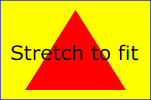
Example 07_12 illustrates the use of the
'viewBox'
attribute on the 'svg'
element to specify that the SVG content must stretch to fit the bounds of the
viewport.
<?xml version="1.0"?>
<svg xmlns="http://www.w3.org/2000/svg" version="1.2" baseProfile="tiny"
     width="300px" height="200px" viewBox="0 0 1500 1000"
     preserveAspectRatio="none">

  <desc>
    Example ViewBox - uses the viewBox attribute to automatically create an
    initial user coordinate system which causes the graphic to scale to fit
    into the viewport no matter what size the viewport is.
  </desc>

  <!-- This rectangle goes from (0,0) to (1500,1000) in user space.
       Because of the viewBox attribute above,
       the rectangle will end up filling the entire area
       reserved for the SVG content. -->
  <rect x="0" y="0" width="1500" height="1000"
        fill="yellow" stroke="blue" stroke-width="12"/>

  <!-- A large, red triangle -->
  <path fill="red"  d="M 750,100 L 250,900 L 1250,900 z"/>

  <!-- A text string that spans most of the viewport -->
  <text x="100" y="600" font-size="200" font-family="Verdana">
    Stretch to fit
  </text>
</svg>
 |
|
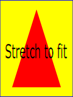 |
Rendered into viewport with
width=300px, height=200px |
|
width=150px,
height=200px |
The effect of the
'viewBox'
attribute is that the
SVG user agent
automatically supplies the appropriate transformation matrix to map the
specified rectangle in user space to the bounds of a designated region
(often, the viewport). To achieve the effect of the example on the left, with
viewport
dimensions of 300 by 200 pixels, the
SVG user agent
needs to automatically insert a transformation which scales both x
and y by 0.2. The effect is equivalent to having a
viewport
of size 300px by 200px and the following supplemental transformation in the
document, as follows:
<svg xmlns="http://www.w3.org/2000/svg" version="1.2" baseProfile="tiny"
     width="300px" height="200px">
  <g transform="scale(0.2)">
    <!-- Rest of document goes here -->
  </g>
</svg>
To achieve the effect of the example on the right, with
viewport
dimensions of 150 by 200 pixels, the
SVG user agent
needs to automatically insert a transformation which scales x by
0.1 and y by 0.2. The effect is equivalent to having a
viewport
of size 150px by 200px and the following supplemental transformation in the
document, as follows:
<svg xmlns="http://www.w3.org/2000/svg" version="1.2" baseProfile="tiny"
     width="150px" height="200px">
  <g transform="scale(0.1 0.2)">
    <!-- Rest of document goes here -->
  </g>
</svg>
(Note: in some cases the
SVG user agent
will need to supply a translate transformation in addition
to a scale transformation. For example, on an
'svg'
element, a translate transformation will be needed if the
'viewBox'
attribute specifies values other than zero for
<min-x> or
<min-y>.)
Unlike the 'transform'
attribute (see effect
of the 'transform' attribute on sibling
attributes), the automatic transformation that is created due to a
'viewBox'
does not affect the 'x',
'y', 'width' and
'height' attributes on the element with the
'viewBox'
attribute. Thus, in the example above which shows an
'svg'
element which has attributes
'width',
'height'
and 'viewBox',
the 'width'
and 'height'
attributes represent values in the coordinate system that exists before
the 'viewBox'
transformation is applied. On the other hand, like the
'transform'
attribute, it does establish a new coordinate system for all other attributes
and for descendant elements.
The following is an EBNF grammar for values of the
'viewBox'
attribute [EBNF]:
viewbox ::=
    wsp* viewboxSpec wsp*
viewboxSpec ::=
    number comma-wsp number comma-wsp number comma-wsp number
    | "none"
number ::=
    sign? integer-constant
    | sign? floating-point-constant
comma-wsp ::=
    (wsp+ comma? wsp*) | (comma wsp*)
comma ::=
    ","
integer-constant ::=
    digit-sequence
floating-point-constant ::=
    fractional-constant exponent?
    | digit-sequence exponent
fractional-constant ::=
    digit-sequence? "." digit-sequence
    | digit-sequence "."
exponent ::=
    ( "e" | "E" ) sign? digit-sequence
sign ::=
    "+" | "-"
digit-sequence ::=
    digit
    | digit digit-sequence
digit ::=
    "0" | "1" | "2" | "3" | "4" | "5" | "6" | "7" | "8" | "9"
wsp ::=
    (#x20 | #x9 | #xD | #xA)
7.9 The 'preserveAspectRatio'
attribute
In some cases, typically when using the 'viewBox' attribute, it is desirable
that the graphics stretch to fit non-uniformly to take up the
entire viewport. In other cases, it is desirable that uniform
scaling be used for the purposes of preserving the aspect ratio
of the graphics.
'preserveAspectRatio' is available for all
elements that establish a new viewport (see elements that
establish viewports), indicates
whether or not to force uniform scaling.
'preserveAspectRatio' only applies when
a value has been provided for 'viewBox' on the same element. Or, in some cases, if an implicit
'viewBox' value can be established for the element (see each element description for details on
this). If a 'viewBox' value can not be determined then
'preserveAspectRatio' is
ignored.
Attribute definition:
-
preserveAspectRatio =
["defer"] <align> [<meet>]
-
- defer
- If the value of 'preserveAspectRatio' on an element that references data ('image',
'animation' and 'video') starts with
defer then the value of the 'preserveAspectRatio' attribute on the
referenced content if present must be used. If the
referenced content lacks a value for 'preserveAspectRatio' then the 'preserveAspectRatio' attribute must
be processed as normal (ignoring defer). For 'preserveAspectRatio' on all other
elements the defer portion of the attribute is ignored.
- <align>
- Indicates whether to force uniform scaling and, if so, the
alignment method to use in case the aspect ratio of the 'viewBox' doesn't match the aspect
ratio of the viewport. The <align> parameter must be one
of the following strings:
- none - Do not force
uniform scaling. Scale the graphic content of the given
element non-uniformly if necessary such that the element's
bounding box exactly matches the viewport rectangle.
- xMinYMin - Force uniform
scaling.
Align the <min-x> of
the element's 'viewBox' with the smallest X
value of the viewport.
Align the <min-y> of
the element's 'viewBox' with the smallest Y
value of the viewport.
- xMidYMin - Force uniform
scaling.
Align the midpoint X value of the element's 'viewBox' with the midpoint X
value of the viewport.
Align the <min-y> of
the element's 'viewBox' with the smallest Y
value of the viewport.
- xMaxYMin - Force uniform
scaling.
Align the <min-x>+<width> of the
element's 'viewBox' with the maximum X value
of the viewport.
Align the <min-y> of
the element's 'viewBox' with the smallest Y
value of the viewport.
- xMinYMid - Force uniform
scaling.
Align the <min-x> of
the element's 'viewBox' with the smallest X
value of the viewport.
Align the midpoint Y value of the element's 'viewBox' with the midpoint Y
value of the viewport.
- xMidYMid (the lacuna value) -
Force uniform scaling.
Align the midpoint X value of the element's 'viewBox' with the midpoint X
value of the viewport.
Align the midpoint Y value of the element's 'viewBox' with the midpoint Y
value of the viewport.
- xMaxYMid - Force uniform
scaling.
Align the <min-x>+<width> of the
element's 'viewBox' with the maximum X value
of the viewport.
Align the midpoint Y value of the element's 'viewBox' with the midpoint Y
value of the viewport.
- xMinYMax - Force uniform
scaling.
Align the <min-x> of
the element's 'viewBox' with the smallest X
value of the viewport.
Align the <min-y>+<height> of the
element's 'viewBox' with the maximum Y value
of the viewport.
- xMidYMax - Force uniform
scaling.
Align the midpoint X value of the element's 'viewBox' with the midpoint X
value of the viewport.
Align the <min-y>+<height> of the
element's 'viewBox' with the maximum Y value
of the viewport.
- xMaxYMax - Force uniform
scaling.
Align the <min-x>+<width> of the
element's 'viewBox' with the maximum X value
of the viewport.
Align the <min-y>+<height> of the
element's 'viewBox' with the maximum Y value
of the viewport.
- <meet>
- Optional and only available due to historical reasons.
The <meet> is separated from the
<align> value by one or
more spaces and must equal the string meet.
meet indicates to scale
the graphic such that:
- aspect ratio is preserved
- the entire 'viewBox' is visible within
the viewport
- the 'viewBox' is scaled up as much
as possible, while still meeting the other criteria
In this case, if the aspect ratio of the graphic does not
match the viewport, some of the viewport will extend beyond
the bounds of the 'viewBox' (i.e., the area into
which the 'viewBox' will draw will be
smaller than the viewport).
Animatable:
yes.
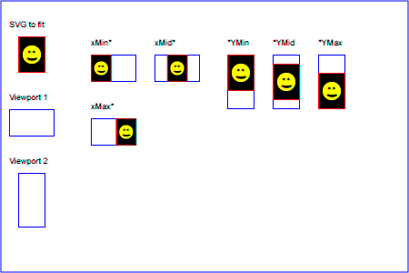
Example PreserveAspectRatio
illustrates the various options on 'preserveAspectRatio'. The example
creates several new viewports by
including 'animation' elements (see Establishing a new
viewport).
Example PreserveAspectRatio
 |
7.10 Establishing a new viewport
Some elements establish a new viewport. By establishing a new viewport, you
implicitly establish a new viewport coordinate system and a new
user coordinate system.
Additionally, there is a new meaning for percentage units
defined to be relative to the current viewport since a new
viewport has been established (see Units).
'viewport-fill' and
'viewport-fill-opacity' properties can
be applied on the new viewport.
The bounds of the new viewport are defined by the 'x', 'y',
'width' and 'height' attributes on the element
establishing the new viewport, such as an 'animation' element. Both the new
viewport coordinate system
and the new user coordinate system
have their origins at (x, y), where x and y
represent the value of the corresponding attributes on the
element establishing the viewport. The orientation of the new
viewport coordinate system
and the new user coordinate system
correspond to the orientation of the current user coordinate system
for the element establishing the viewport. A single unit
in the new viewport coordinate system
and the new user coordinate system are the same size as a single unit in the
current user coordinate system for the element establishing the
viewport.
For an extensive example of creating new viewports, see Example
PreserveAspectRatio.
The following elements establish new viewports:
The following paragraph is informative.
Note that no clipping of overflow is performed, but that such
clipping will take place if the content is viewed in an SVG user agent
that supports clipping (e.g. a user agent that supports SVG 1.1 Full [SVG11]), since the initial value for the
'overflow' property is hidden for non-root elements that establish viewports ([SVG11], section 14.3.3). Content
authors that want content to be fully forward compatible are advised to
either specify the 'overflow'
property or to make sure that content that shouldn't be clipped is inside of
the established viewport.
7.11 Units
Besides the exceptions listed below all coordinates and lengths
in SVG must be specified in user units, which means that unit identifiers are not allowed.
Two exceptions exist:
A user unit is a value in the current user coordinate system. For example:
<text font-size="50">Text size is 50 user units</text>
For the 'svg' element's 'width' and 'height' attributes
a coordinate or length value can be expressed
as a number following by a unit identifier (e.g., '25cm' or
'100%'). The list of unit identifiers in SVG are:
in, cm, mm, pt, pc, px and percentages (%).
These values on 'width' and 'height' contribute towards the calculation of the initial viewport.
Using percentage values on 'width' and 'height' attributes mandates how much
space the SVG viewport must take of the available initial viewport. In particular:
See the discussion on the initial viewport for more details.
7.12 Bounding box
The bounding box (or "bbox") of an element is the tightest fitting
rectangle aligned with the axes of that element's
user coordinate system
that entirely encloses it and its descendants. The bounding box must
be computed exclusive of any values for the
fill related properties,
the stroke related properties,
the opacity related properties
or the visibility
property. For curved shapes, the bounding box must enclose all
portions of the shape along the edge, not just end points.
Note that control points for a curve which are not defined as
lying along the line of the resulting curve (e.g., the second
coordinate pair of a
Cubic Bézier command)
must not contribute to the dimensions of the bounding box
(though those points may fall within the area of the bounding
box, if they lie within the shape itself, or along or close to
the curve). For example, control points of a curve that are at
a further distance than the curve edge, from the non-enclosing
side of the curve edge, must be excluded from the bounding box.
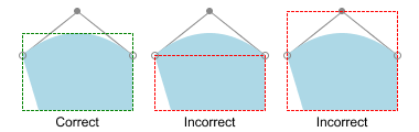
Example bbox01 shows one shape (a
'path'
element with a quadratic Bézier curve) with three possible bounding boxes,
only the leftmost of which is correct.
<svg xmlns='http://www.w3.org/2000/svg'
     xmlns:xlink='http://www.w3.org/1999/xlink'
     version='1.1' width='380px' height='120px' viewBox='0 0 380 120'>

  <title>Bounding Box of a Path</title>
  <desc>
    Illustration of one shape (a 'path' element with a quadratic Bézier) with
    three bounding boxes, only one of which is correct.
  </desc>

  <defs>
    <g id='shape'>
      <line x1='120' y1='50' x2='70' y2='10' stroke='#888'/>
      <line x1='20' y1='50' x2='70' y2='10' stroke='#888'/>
      <path stroke-width='2' fill='rgb(173, 216, 230)' stroke='none' fill-rule='evenodd'
            d='M20,50
               L35,100
               H120
               V50
               Q70,10 20,50'/>
      <circle cx='120' cy='50' r='3' fill='none' stroke='#888'/>
      <circle cx='20' cy='50' r='3' fill='none' stroke='#888'/>
      <circle cx='70' cy='10' r='3' fill='#888' stroke='none'/>
    </g>
  </defs>

  <g text-anchor='middle'>
    <g>
      <title>Correct Bounding Box</title>
      <use xlink:href='#shape'/>
      <rect x='20' y='30' width='100' height='70'
            fill='none' stroke='green' stroke-dasharray='2' stroke-linecap='round'/>
      <text x='70' y='115'>Correct</text>
    </g>

    <g transform='translate(120)'>
      <title>Incorrect Bounding Box</title>
      <desc>Bounding box does not encompass entire shape.</desc>
      <use xlink:href='#shape'/>
      <rect x='20' y='50' width='100' height='50'
            fill='none' stroke='red' stroke-dasharray='2' stroke-linecap='round'/>
      <text x='70' y='115'>Incorrect</text>
    </g>

    <g transform='translate(240)'>
      <title>Incorrect Bounding Box</title>
      <desc>Bounding box includes control points outside shape.</desc>
      <use xlink:href='#shape'/>
      <rect x='20' y='10' width='100' height='90'
            fill='none' stroke='red' stroke-dasharray='2' stroke-linecap='round'/>
      <text x='70' y='115'>Incorrect</text>
    </g>
  </g>
</svg>
The bounding box must be applicable for any rendering element with positive
'width'
or 'height'
attributes and with a
'display'
property other than none, as well as
for any container element that may contain such elements. Elements
which do not partake in the rendering tree (e.g. elements in a
'defs'
element, elements whose
'display'
is none, etc.), and which have no
child elements that partake in the rendering tree (e.g.
'g'
elements with no children), shall not contribute to the bounding box
of the parent element. Elements that do not contribute to the bounding box
of a parent element must still return their own bounding box value when
required.
To illustrate, example bbox-calc below shows a set of elements. Given this example, the following results shall be calculated for each of the elements.
<svg xmlns="http://www.w3.org/2000/svg"
     xmlns:xlink="http://www.w3.org/1999/xlink">

  <title>Bounding Box Calculation</title>
  <desc>Examples of elements with different bounding box results based on context.</desc>

  <defs id="defs-1">
     <rect id="rect-1" x="20" y="20" width="40" height="40" fill="blue" />
  </defs>

  <g id="group-1">
    <use id="use-1" xlink:href="#rect-1" x="10" y="10" />

    <g id="group-2" display="none">
      <rect id="rect-2" x="10" y="10" width="100" height="100" fill="red" />
    </g>
  </g>
</svg>
| Element ID |
Bounding Box Result |
"defs-1" |
{0, 0, 0, 0} |
"rect-1" |
{20, 20, 40, 40} |
"group-1" |
{30, 30, 40, 40} |
"use-1" |
{30, 30, 40, 40} |
"group-2" |
{10, 10, 100, 100} |
"rect-2" |
{10, 10, 100, 100} |
Elements and document fragments which derive from
SVGLocatable
but are not in the rendering tree, such as those in a
'defs'
element or those which have been been created but not yet inserted
into the DOM, must still have a bounding box. The geometry of
elements outside the rendering tree must take into account only those
properties and values (such as
'font-size')
which are specified within that element or document fragment, or which
have a lacuna value
or an implementation-defined value.
For
text
content elements, for the purposes of the bounding box
calculation, each glyph must be treated as a separate graphics element.
The calculations must assume that all glyphs occupy the full
glyph cell. For example, for horizontal text, the calculations must
assume that each glyph extends vertically to the full ascent and
descent values for the font. An exception to this is the
'textArea',
which uses that element's geometry for the bounding box calculation.
Because declarative or scripted animation can change the shape, size,
and position of an element, the bounding box is mutable. Thus, the
bounding box for an element shall reflect the current values for the
element at the snapshot in time at which the bounding box is
requested, whether through a script call or as part of a declarative
or linking syntax.
Note that an element which has either or both of
'width' and
'height' of
'0' (such as a vertical or horizontal
line, or a
'rect'
element with an unspecified 'width' or
'height') still has a bounding box,
with a positive value for the positive dimension, or with
'0' for both
'width' and
'height' if no positive dimension is
specified. Similarly, subpaths segments of a
'path'
element with '0'
'width' and
'height' must be included in that
element's geometry for the sake of the bounding box. Note also that
elements which do not derive from
SVGLocatable
(such as gradient elements) do
not have a bounding box, thus have no interface to request a bounding
box.
Elements in the rendering tree
which reference unresolved resources shall still have
a bounding box, defined by the position and dimensions specified in their attributes, or by the
lacuna value for those attributes if
no values are supplied. For example, the element <use xlink:href="#bad" x="10" y="10"/>
would have a bounding box with an 'x' and 'y'
of '10' and a 'width' and
'height' of '0'.
For a formal definition of bounding boxes, see
[FOLEY-VANDAM],
section 15.2.3, Extents and Bounding Volumes. For further details, see
bounding box
calculations, the
effects of visibility on bounding box,
object bounding
box units and text elements, and
fragment
identifiers.
7.13 Object bounding box units
The following elements offer the option of expressing
coordinate values and lengths as fractions of
the bounding box
(via keyword 'objectBoundingBox')
on a given element:
In the discussion that follows, the term applicable element is the element to
which the given effect applies. For gradients the
applicable element is the graphics element
which has its 'fill' or 'stroke' property referencing the
given gradient. (See Inheritance
of painting properties. For special rules concerning text elements, see the discussion of object
bounding box units and text elements.)
When keyword 'objectBoundingBox' is used, then the
effect is as if a supplemental transformation matrix were
inserted into the list of nested transformation matrices to
create a new user coordinate system.
First, the (minx, miny) and
(maxx, maxy) coordinates are
determined for the applicable element and all of its
descendants. The values minx,
miny, maxx and
maxy are determined by computing the maximum
extent of the shape of the element in x and y with respect to
the user coordinate system for the applicable element.
Then, coordinate (0, 0) in the new user coordinate system is
mapped to the (minx, miny) corner of the tight bounding box
within the user coordinate system of the applicable element and
coordinate (1, 1) in the new user coordinate system is mapped to
the (maxx, maxy) corner of the tight bounding box of the
applicable element. In most situations, the following
transformation matrix produces the correct effect:
[ (maxx-minx) 0 0 (maxy-miny) minx miny ]
Any numeric value can be specified for values expressed as a
fraction of object bounding box units. In
particular, fractions less are zero or greater than one can be
specified.
Keyword 'objectBoundingBox'
should not be used when the geometry of the applicable element
has no width or no height, such as the case of a horizontal or
vertical line, even when the line has actual thickness when
viewed due to having a non-zero stroke width since stroke width
is ignored for bounding box calculations. When the geometry of
the applicable element has no width or height and 'objectBoundingBox' is specified, then
the given effect (e.g., a gradient) will be
ignored.
7.14 Intrinsic sizing properties of the viewport of SVG content
SVG needs to specify how to calculate some intrinsic sizing properties to
enable inclusion within other languages. The intrinsic width and height
of the viewport of SVG content must be determined from the 'width' and 'height'
attributes. If either of these are not specified, the lacuna value of '100%' must
be used. Note: the 'width' and 'height'
attributes are not the same as the CSS width and height properties. Specifically, percentage values do not
provide an intrinsic width or height, and do not indicate a percentage of the containing block. Rather, they indicate the portion of the viewport that is actually covered by image data.
The intrinsic aspect ratio of the viewport of SVG content is necessary
for example, when including SVG from an object element in XHTML styled with
CSS. It is possible (indeed, common) for an SVG graphic to have an intrinsic aspect ratio but not to have an intrinsic width or height.
The intrinsic aspect ratio must be calculated based upon the
following rules:
The aspect ratio is calculated by dividing a width by a height.
If the 'width' and 'height' of the rootmost 'svg' element are both specified with
unit identifiers (in, mm, cm, pt, pc, px, em, ex) or in user units, then the aspect ratio is
calculated from the 'width' and 'height' attributes after resolving both values to user units.
If either/both of the 'width' and 'height' of the rootmost 'svg' element are in
percentage units (or omitted), the aspect ratio is calculated from the width and
height values of the 'viewBox' specified for the current SVG document fragment. If the 'viewBox' is not correctly specified, or set to 'none',
the intrinsic aspect ratio cannot be calculated and is considered unspecified.
Examples:
<svg xmlns="http://www.w3.org/2000/svg" version="1.2" baseProfile="tiny"
     width="10cm" height="5cm">
  ...
</svg>
In this example the intrinsic aspect ratio of the viewport is 2:1. The
intrinsic width is 10cm and the intrinsic height is 5cm.
<svg xmlns="http://www.w3.org/2000/svg" version="1.2" baseProfile="tiny"
     width="100%" height="50%" viewBox="0 0 200 200">
  ...
</svg>
In this example the intrinsic aspect ratio of the rootmost viewport is
1:1. An aspect ratio calculation in this case allows embedding in an
object within a containing block that is only constrained in one direction.
<svg xmlns="http://www.w3.org/2000/svg" version="1.2" baseProfile="tiny"
     width="10cm" viewBox="0 0 200 200">
  ...
</svg>
In this case the intrinsic aspect ratio is 1:1.
<svg xmlns="http://www.w3.org/2000/svg" version="1.2" baseProfile="tiny"
     width="75%" height="10cm" viewBox="0 0 200 200">
  ...
</svg>
In this example, the intrinsic aspect ratio is 1:1.
7.15 Geographic coordinate systems
In order to allow interoperability between SVG content
generators and SVG user agents dealing with maps encoded in SVG,
the use of a common metadata definition for describing the coordinate system
used to generate SVG documents is encouraged.
Such metadata must be added under the 'metadata' element of the topmost
'svg' element describing the
map, consisting of an RDF description of the Coordinate
Reference System definition used to generate the SVG map [RDF].
Note that the presence of this metadata
does not affect the rendering of the SVG in any way; it merely provides added
semantic value for applications that make use of combined maps.
The definition must be conformant to the XML grammar
described in GML 3.2.1,
an OpenGIS Standard for encoding common CRS data types in XML
[GML]. In order to correctly map the
2-dimensional data used by SVG, the CRS must be of subtype ProjectedCRS or
Geographic2dCRS. The first axis of the described CRS maps the SVG x-axis and
the second axis maps the SVG y-axis.
The main purpose of such metadata is to indicate to the user
agent that two or more SVG documents can be overlayed or merged
into a single document. Obviously, if two maps reference the
same Coordinate Reference System definition and have the same
SVG 'transform' attribute value then they can be overlayed
without reprojecting the data. If the maps reference different
Coordinate Reference Systems and/or have different SVG
'transform' attribute values, then a specialized cartographic
user agent may choose to transform the coordinate data to
overlay the data. However, typical SVG user agents are not
required to perform these types of transformations, or even
recognize the metadata. It is described in this specification so that the connection between geographic coordinate systems and the SVG coordinate system is clear.
Attribute definition:
- svg:transform = "<transform>" | "none"
-
- <transform>
-
Specifies the affine transformation that has been applied to the
map data. The syntax is identical to that described in
The 'transform' attribute
section.
- none
-
Specifies that no supplemental affine transformation has been
applied to the map data. Using this value has the same meaning as
specifying the identity matrix, which in turn is just the same as
not specifying the
'svg:transform'
the attribute at all.
Animatable: no.
This attribute describes an optional additional affine transformation
that may
have been applied during this mapping. This attribute may be added
to the OpenGIS 'CoordinateReferenceSystem'
element. Note that, unlike the 'transform'
attribute, it does
not indicate that a transformation is to be applied to the
data within the file. Instead, it simply describes the transformation
that was already applied to the data when being encoded in SVG.
There are three typical uses for the 'svg:transform' global
attribute. These are described below and used in the
examples.
Most ProjectedCRS have the north direction represented by
positive values of the second axis and conversely SVG has a
y-down coordinate system. That's why, in order to follow the
usual way to represent a map with the north at its top, it is
recommended for that kind of ProjectedCRS to use the
'svg:transform'
global attribute with a 'scale(1, -1)' value as in the
third example below.
Most Geographic2dCRS have the latitude as their first
axis rather than the longitude, which means that the
south-north axis would be represented by the x-axis in SVG
instead of the usual y-axis. That's why, in order to follow
the usual way to represent a map with the north at its top,
it is recommended for that kind of Geographic2dCRS to use the
'svg:transform'
global attribute with a 'rotate(-90)' value as in the
first example (while also adding the 'scale(1, -1)' as for
ProjectedCRS).
In addition, when converting for profiles which place
restrictions on precision of real number values, it may be
useful to add an additional scaling factor to retain good
precision for a specific area. When generating an SVG
document from WGS84 geographic coordinates (EPGS 4326), we
recommend the use of an additional 100 times scaling factor
corresponding to an 'svg:transform'
global attribute with a 'rotate(-90) scale(100)'
value (shown in the second example).
Different scaling values may be required depending on the
particular CRS.
Below is a simple example of the coordinate metadata, which
describes the coordinate system used by the document via a
URI.
<?xml version="1.0"?>
<svg xmlns="http://www.w3.org/2000/svg" version="1.2" baseProfile="tiny"
     width="100" height="100" viewBox="0 0 1000 1000">

  <desc>An example that references coordinate data.</desc>

  <metadata>
    <rdf:RDF xmlns:rdf="http://www.w3.org/1999/02/22-rdf-syntax-ns#"
             xmlns:crs="http://www.ogc.org/crs"
             xmlns:svg="http://wwww.w3.org/2000/svg">
      <rdf:Description rdf:about="">
        <!-- The Coordinate Reference System is described
             through a URI. -->
        <crs:CoordinateReferenceSystem
            svg:transform="rotate(-90)"
            rdf:resource="http://www.example.org/srs/epsg.xml#4326"/>
      </rdf:Description>
    </rdf:RDF>
  </metadata>

  <!-- The actual map content -->
</svg>
The second example uses a well-known identifier to describe
the coordinate system. Note that the coordinates used in the
document have had the supplied transform applied.
<?xml version="1.0"?>
<svg xmlns="http://www.w3.org/2000/svg" version="1.2" baseProfile="tiny"
     width="100" height="100" viewBox="0 0 1000 1000">

  <desc>Example using a well known coordinate system.</desc>

  <metadata>
    <rdf:RDF xmlns:rdf="http://www.w3.org/1999/02/22-rdf-syntax-ns#"
             xmlns:crs="http://www.ogc.org/crs"
             xmlns:svg="http://wwww.w3.org/2000/svg">
      <rdf:Description rdf:about="">
        <!-- In case of a well-known Coordinate Reference System
             an 'Identifier' is enough to describe the CRS -->
        <crs:CoordinateReferenceSystem svg:transform="rotate(-90) scale(100, 100)">
          <crs:Identifier>
            <crs:code>4326</crs:code>
            <crs:codeSpace>EPSG</crs:codeSpace>
            <crs:edition>5.2</crs:edition>
          </crs:Identifier>
        </crs:CoordinateReferenceSystem>
      </rdf:Description>
    </rdf:RDF>
  </metadata>

  <!-- The actual map content -->
</svg>
The third example defines the coordinate system completely
within the SVG document.
<?xml version="1.0"?>
<svg xmlns="http://www.w3.org/2000/svg" version="1.2" baseProfile="tiny"
     width="100" height="100" viewBox="0 0 1000 1000">

  <desc>Coordinate metadata defined within the SVG document</desc>

  <metadata>
    <rdf:RDF xmlns:rdf="http://www.w3.org/1999/02/22-rdf-syntax-ns#"
             xmlns:crs="http://www.ogc.org/crs"
             xmlns:svg="http://wwww.w3.org/2000/svg">
      <rdf:Description rdf:about="">
        <!-- For other CRS it should be entirely defined -->
        <crs:CoordinateReferenceSystem svg:transform="scale(1,-1)">
          <crs:NameSet>
            <crs:name>Mercator projection of WGS84</crs:name>
          </crs:NameSet>
          <crs:ProjectedCRS>
            <!-- The actual definition of the CRS -->
            <crs:CartesianCoordinateSystem>
              <crs:dimension>2</crs:dimension>
              <crs:CoordinateAxis>
                <crs:axisDirection>north</crs:axisDirection>
                <crs:AngularUnit>
                  <crs:Identifier>
                    <crs:code>9108</crs:code>
                    <crs:codeSpace>EPSG</crs:codeSpace>
                    <crs:edition>5.2</crs:edition>
                  </crs:Identifier>
                </crs:AngularUnit>
              </crs:CoordinateAxis>
              <crs:CoordinateAxis>
                <crs:axisDirection>east</crs:axisDirection>
                <crs:AngularUnit>
                  <crs:Identifier>
                    <crs:code>9108</crs:code>
                    <crs:codeSpace>EPSG</crs:codeSpace>
                    <crs:edition>5.2</crs:edition>
                  </crs:Identifier>
                </crs:AngularUnit>
              </crs:CoordinateAxis>
            </crs:CartesianCoordinateSystem>
            <crs:CoordinateReferenceSystem>
              <!-- the reference system of that projected system is
                         WGS84 which is EPSG 4326 in EPSG codeSpace -->
              <crs:NameSet>
                <crs:name>WGS 84</crs:name>
              </crs:NameSet>
              <crs:Identifier>
                <crs:code>4326</crs:code>
                <crs:codeSpace>EPSG</crs:codeSpace>
                <crs:edition>5.2</crs:edition>
              </crs:Identifier>
            </crs:CoordinateReferenceSystem>
            <crs:CoordinateTransformationDefinition>
              <crs:sourceDimensions>2</crs:sourceDimensions>
              <crs:targetDimensions>2</crs:targetDimensions>
              <crs:ParameterizedTransformation>
                <crs:TransformationMethod>
                  <!-- the projection is a Mercator projection which is
                        EPSG 9805 in EPSG codeSpace -->
                  <crs:NameSet>
                    <crs:name>Mercator</crs:name>
                  </crs:NameSet>
                  <crs:Identifier>
                    <crs:code>9805</crs:code>
                    <crs:codeSpace>EPSG</crs:codeSpace>
                    <crs:edition>5.2</crs:edition>
                  </crs:Identifier>
                  <crs:description>Mercator (2SP)</crs:description>
                </crs:TransformationMethod>
                <crs:Parameter>
                  <crs:NameSet>
                    <crs:name>Latitude of 1st standart parallel</crs:name>
                  </crs:NameSet>
                  <crs:Identifier>
                    <crs:code>8823</crs:code>
                    <crs:codeSpace>EPSG</crs:codeSpace>
                    <crs:edition>5.2</crs:edition>
                  </crs:Identifier>
                  <crs:value>0</crs:value>
                </crs:Parameter>
                <crs:Parameter>
                  <crs:NameSet>
                    <crs:name>Longitude of natural origin</crs:name>
                  </crs:NameSet>
                  <crs:Identifier>
                    <crs:code>8802</crs:code>
                    <crs:codeSpace>EPSG</crs:codeSpace>
                    <crs:edition>5.2</crs:edition>
                  </crs:Identifier>
                  <crs:value>0</crs:value>
                </crs:Parameter>
                <crs:Parameter>
                  <crs:NameSet>
                    <crs:name>False Easting</crs:name>
                  </crs:NameSet>
                  <crs:Identifier>
                    <crs:code>8806</crs:code>
                    <crs:codeSpace>EPSG</crs:codeSpace>
                    <crs:edition>5.2</crs:edition>
                  </crs:Identifier>
                  <crs:value>0</crs:value>
                </crs:Parameter>
                <crs:Parameter>
                  <crs:NameSet>
                    <crs:name>False Northing</crs:name>
                  </crs:NameSet>
                  <crs:Identifier>
                    <crs:code>8807</crs:code>
                    <crs:codeSpace>EPSG</crs:codeSpace>
                    <crs:edition>5.2</crs:edition>
                  </crs:Identifier>
                  <crs:value>0</crs:value>
                </crs:Parameter>
              </crs:ParameterizedTransformation>
            </crs:CoordinateTransformationDefinition>
          </crs:ProjectedCRS>
        </crs:CoordinateReferenceSystem>
      </rdf:Description>
    </rdf:RDF>
  </metadata>

  <!-- the actual map content -->
</svg>

