This specification describes a high-level JavaScript API for processing and
synthesizing audio in web applications. The primary paradigm is of an
audio routing graph, where a number of AudioNode
objects are connected together to define the overall audio rendering.
The actual processing will primarily take place in the underlying
implementation (typically optimized Assembly / C / C++ code), but
direct JavaScript processing and
synthesis is also supported.
The introductory section covers the
motivation behind this specification.
This API is designed to be used in conjunction with other APIs and
elements on the web platform, notably: XMLHttpRequest [XHR] (using
the responseType and response attributes).
For games and interactive applications, it is anticipated to be used
with the canvas 2D [2dcontext] and WebGL [WEBGL] 3D
graphics APIs.
Status of This Document
This section describes the status of this document at the time of its publication. Other documents may supersede this document. A list of current W3C publications and the latest revision of this technical report can be found in the W3C technical reports index at http://www.w3.org/TR/.
This document was published by the Audio Working Group as a Working Draft.
This document is intended to become a W3C Recommendation.
If you wish to make comments regarding this document, please send them to
public-audio@w3.org
(subscribe,
archives).
All comments are welcome.
Publication as a Working Draft does not imply endorsement by the W3C
Membership. This is a draft document and may be updated, replaced or obsoleted by other
documents at any time. It is inappropriate to cite this document as other than work in
progress.
Audio on the web has been fairly primitive up to this point and until
very recently has had to be delivered through plugins such as Flash
and QuickTime. The introduction of the audio element in
HTML5 is very important, allowing for basic streaming audio playback.
But, it is not powerful enough to handle more complex audio
applications. For sophisticated web-based games or interactive
applications, another solution is required. It is a goal of this
specification to include the capabilities found in modern game audio
engines as well as some of the mixing, processing, and filtering
tasks that are found in modern desktop audio production applications.
The APIs have been designed with a wide variety of use cases
[webaudio-usecases] in mind. Ideally, it should be able to support
any use case which could reasonably be implemented with an
optimized C++ engine controlled via JavaScript and run in a browser.
That said, modern desktop audio software can have very advanced
capabilities, some of which would be difficult or impossible to build
with this system. Apple's Logic Audio is one such application which
has support for external MIDI controllers, arbitrary plugin audio
effects and synthesizers, highly optimized direct-to-disk audio file
reading/writing, tightly integrated time-stretching, and so on.
Nevertheless, the proposed system will be quite capable of supporting
a large range of reasonably complex games and interactive
applications, including musical ones. And it can be a very good
complement to the more advanced graphics features offered by WebGL.
The API has been designed so that more advanced capabilities can be
added at a later time.
Efficient biquad filters for lowpass, highpass, and other common
filters.
A Waveshaping effect for distortion and other non-linear effects
Oscillators
0.1.1
Modular Routing
Modular routing allows arbitrary connections between different
AudioNode objects. Each node can have
inputs and/or outputs. A source
node has no inputs and a single output. A destination
node has one input and no outputs, the most common example
being AudioDestinationNode the
final destination to the audio hardware. Other nodes such as
filters can be placed between the source and destination nodes. The
developer doesn't have to worry about low-level stream format
details when two objects are connected together; the right thing just
happens. For example, if a mono audio stream is connected to a
stereo input it should just mix to left and right channels appropriately.
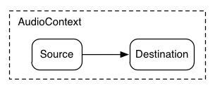
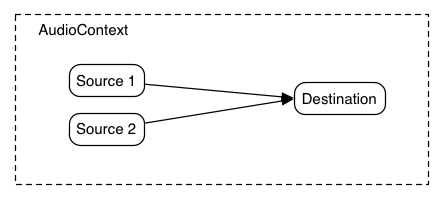
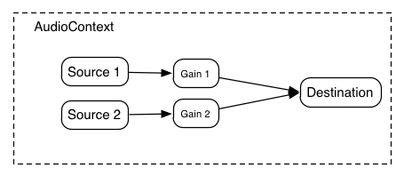
In the simplest case, a single source can be routed directly to the
output. All routing occurs within an AudioContext containing a single
AudioDestinationNode:
Fig. 1
A simple example of modular routing.
Illustrating this simple routing, here's a simple example playing a
single sound:
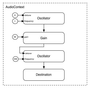
Modular routing also permits the output of
AudioNodes to be routed to an
AudioParam parameter that controls the behavior
of a different AudioNode. In this scenario, the
output of a node can act as a modulation signal rather than an
input signal.
Fig. 3
Modular routing illustrating one Oscillator modulating the
frequency of another.
Example 3
function setupRoutingGraph(){var context =newAudioContext();// Create the low frequency oscillator that supplies the modulation signalvar lfo = context.createOscillator();
lfo.frequency.value =1.0;// Create the high frequency oscillator to be modulatedvar hfo = context.createOscillator();
hfo.frequency.value =440.0;// Create a gain node whose gain determines the amplitude of the modulation signalvar modulationGain = context.createGain();
modulationGain.gain.value =50;// Configure the graph and start the oscillators
lfo.connect(modulationGain);
modulationGain.connect(hfo.detune);
hfo.connect(context.destination);
hfo.start(0);
lfo.start(0);}
0.2
API Overview
The interfaces defined are:
An AudioContext
interface, which contains an audio signal graph representing
connections betweens AudioNodes.
An AudioNode interface, which represents
audio sources, audio outputs, and intermediate processing modules.
AudioNodes can be dynamically connected together
in a modular fashion.
AudioNodes exist in the context of an
AudioContext
An AudioWorkerGlobalScope interface, the
context in which AudioWorker processing scripts run.
An AudioWorkerNodeProcessor interface,
representing a single node instance inside an audio worker.
An AudioParam interface, for controlling an
individual aspect of an AudioNode's functioning,
such as volume.
An GainNode interface, an
AudioNode for explicit gain control. Because
inputs to AudioNodes support multiple connections
(as a unity-gain summing junction), mixers can be easily built with GainNodes.
There are also several features that have been deprecated from the
Web Audio API but not yet removed, pending implementation experience
of their replacements:
As well as sections marked as non-normative, all authoring guidelines, diagrams, examples,
and notes in this specification are non-normative. Everything else in this specification is
normative.
The key words MUST, REQUIRED, and SHALL are
to be interpreted as described in [RFC2119].
The following conformance classes are defined by this specification:
conforming
implementation
A user agent is considered to be a conforming implementation if
it satisfies all of the MUST-, REQUIRED- and SHALL-level criteria
in this specification that apply to implementations.
User agents that use ECMAScript to implement the APIs defined in this
specification must implement them in a manner consistent with the
ECMAScript Bindings defined in the Web IDL specification [WEBIDL] as
this specification uses that specification and terminology.
2.
The Audio API
2.1
The BaseAudioContext Interface
This interface represents a set of AudioNode
objects and their connections. It allows for arbitrary routing of
signals to an AudioDestinationNode. Nodes are
created from the context and are then connected together.
This context is currently suspended (context time is not
proceeding, audio hardware may be powered down/released).
running
Audio is being processed.
closed
This context has been released, and can no longer be used to
process audio. All system audio resources have been released.
Attempts to create new Nodes on this context will throw
InvalidStateError. (AudioBuffers may still be created, through
createBuffer or
decodeAudioData.)
This is the time in seconds of the sample frame immediately
following the last sample-frame in the block of audio most
recently processed by the context's rendering graph. If the
context's rendering graph has not yet processed a block of audio,
then currentTime
has a value of zero.
In the time coordinate system of currentTime,
the value of zero corresponds to the first sample-frame in the
first block processed by the graph. Elapsed time in this system
corresponds to elapsed time in the audio stream generated by the
BaseAudioContext, which may not be
synchronized with other clocks in the system. (For an
OfflineAudioContext, since the stream is not
being actively played by any device, there is not even an
approximation to real time.)
All scheduled times in the Web Audio API are relative to the
value of currentTime.
When the BaseAudioContext is in the running
state, the value of this attribute is monotonically increasing
and is updated by the rendering thread in uniform increments,
corresponding to the audio block size of 128 samples. Thus, for a
running context, currentTime increases steadily as
the system processes audio blocks, and always represents the time
of the start of the next audio block to be processed. It is also
the earliest possible time when any change scheduled in the
current state might take effect.
An AudioDestinationNode
with a single input representing the final destination for all
audio. Usually this will represent the actual audio hardware. All
AudioNodes actively rendering audio will
directly or indirectly connect to destination.
A property used to set the EventHandler for an event
that is dispatched to BaseAudioContext when the
state of the AudioContext has changed (i.e. when the corresponding
promise would have resolved). An event of type
Event will be dispatched to the event handler,
which can query the AudioContext's state directly. A newly-created
AudioContext will always begin in the "suspended" state, and a
state change event will be fired whenever the state changes to a
different state.
sampleRate of type float, readonly
The sample rate (in sample-frames per second) at which the
BaseAudioContext handles audio. It is assumed
that all AudioNodes in the context run at
this rate. In making this assumption, sample-rate converters or
"varispeed" processors are not supported in real-time processing.
Describes the current state of this BaseAudioContext. The context
state MUST begin in "suspended", and transitions to "running" when
system resources are acquired and audio has begun processing. For
OfflineAudioContexts, the state will remain in "suspended" until
startRendering() is called, at which point it will
transition to "running", and then to "closed" once audio processing
has completed and oncomplete has been fired.
When the state is "suspended", a call to resume()
will cause a transition to "running", or a call to
close() will cause a transition to "closed".
When the state is "running", a call to suspend()
will cause a transition to "suspended", or a call to
close() will cause a transition to "closed".
When the state is "closed", no further state transitions are
possible.
2.1.2 Methods
close
Closes the audio context, releasing any system audio resources used
by the BaseAudioContext. This will not
automatically release all BaseAudioContext-created objects, unless
other references have been released as well; however, it will
forcibly release any system audio resources that might prevent
additional AudioContexts from being created and used, suspend the
progression of the BaseAudioContext's currentTime, and stop
processing audio data. The promise resolves when all
AudioContext-creation-blocking resources have been released. If
this is called on OfflineAudioContext, then return a promise
rejected with a DOMException whose name is
InvalidStateError.
Creates an AudioBuffer of the given size. The audio data in the
buffer will be zero-initialized (silent). A NotSupportedError
exception MUST be thrown if any of the arguments is negative, zero,
or outside its nominal range.
Parameter
Type
Nullable
Optional
Description
numberOfChannels
unsigned long
✘
✘
Determines how many channels the buffer will have. An
implementation must support at least 32 channels.
length
unsigned long
✘
✘
Determines the size of the buffer in sample-frames.
sampleRate
float
✘
✘
Describes the sample-rate of the linear PCM audio data in the
buffer in sample-frames per second. An implementation must
support sample rates in at least the range 8192 to 96000.
Creates a DelayNode representing a variable
delay line. The initial default delay time will be 0 seconds.
Parameter
Type
Nullable
Optional
Description
maxDelayTime
double = 1.0
✘
✔
The maxDelayTime parameter is optional and specifies
the maximum delay time in seconds allowed for the delay line.
If specified, this value MUST be greater than zero and less
than three minutes or a NotSupportedError exception MUST be
thrown.
Creates an IIRFilterNode representing a general
IIR Filter.
Parameter
Type
Nullable
Optional
Description
feedforward
sequence<double>
✘
✘
An array of the feedforward (numerator) coefficients for the
transfer function of the IIR filter. The maximum length of this
array is 20. If all of the values are zero, an
InvalidStateError MUST be thrown. A NotSupportedError MUST be
thrown if the array length is 0 or greater than 20.
feedback
sequence<double>
✘
✘
An array of the feedback (denominator) coefficients for the
tranfer function of the IIR filter. The maximum length of this
array is 20. If the first element of the array is 0, an
InvalidStateError MUST be thrown. A NotSupportedError MUST be
thrown if the array length is 0 or greater than 20.
This method is DEPRECATED, as it is intended to be replaced by
createSpatialPanner or createStereoPanner, depending on the
scenario. Creates a PannerNode.
Creates a PeriodicWave representing a waveform
containing arbitrary harmonic content. The real and
imag parameters must be of type
Float32Array (described in [TYPED-ARRAYS]) of equal
lengths greater than zero or an IndexSizeError exception MUST be
thrown. All implementations must support arrays up to at least
8192. These parameters specify the Fourier coefficients of a
Fourier
series representing the partials of a periodic waveform. The
created PeriodicWave will be used with an
OscillatorNode and, by default, will represent
a normalized time-domain waveform having maximum absolute
peak value of 1. Another way of saying this is that the generated
waveform of an OscillatorNode will have maximum
peak value at 0dBFS. Conveniently, this corresponds to the
full-range of the signal values used by the Web Audio API. Because
the PeriodicWave is normalized by default on creation, the
real and imag parameters represent
relative values. If normalization is disabled via the
disableNormalization parameter, this normalization is
disabled, and the time-domain waveform has the amplitudes as given
by the Fourier coefficients.
As PeriodicWave objects maintain their own copies of these
arrays, any modification of the arrays uses as the
real and imag parameters after the call
to
createPeriodicWave() will have no effect on the
PeriodicWave object.
Parameter
Type
Nullable
Optional
Description
real
Float32Array
✘
✘
The real parameter represents an array
of cosine terms (traditionally the A terms). In
audio terminology, the first element (index 0) is the DC-offset
of the periodic waveform. The second element (index 1)
represents the fundamental frequency. The third element
represents the first overtone, and so on. The first element is
ignored and implementations must set it to zero internally.
imag
Float32Array
✘
✘
The imag parameter represents an array
of sine terms (traditionally the B terms). The
first element (index 0) should be set to zero (and will be
ignored) since this term does not exist in the Fourier series.
The second element (index 1) represents the fundamental
frequency. The third element represents the first overtone, and
so on.
The bufferSize parameter determines the
buffer size in units of sample-frames. If it's not passed in,
or if the value is 0, then the implementation will choose the
best buffer size for the given environment, which will be
constant power of 2 throughout the lifetime of the node.
Otherwise if the author explicitly specifies the bufferSize, it
must be one of the following values: 256, 512, 1024, 2048,
4096, 8192, 16384. This value controls how frequently the
audioprocess event is dispatched and how many
sample-frames need to be processed each call. Lower values for
bufferSize will result in a lower (better)
latency. Higher values will be necessary
to avoid audio breakup and glitches. It is recommended for authors
to not specify this buffer size and allow the implementation to
pick a good buffer size to balance between latency and audio quality. If the value of this
parameter is not one of the allowed power-of-2 values listed
above, an IndexSizeError MUST be thrown.
numberOfInputChannels
unsigned long = 2
✘
✔
This parameter determines the number of channels for this
node's input. Values of up to 32 must be supported.
numberOfOutputChannels
unsigned long = 2
✘
✔
This parameter determines the number of channels for this
node's output. Values of up to 32 must be supported.
Asynchronously decodes the audio file data contained in the
ArrayBuffer. The ArrayBuffer can, for example, be loaded from an
XMLHttpRequest's response attribute after setting the
responseType to "arraybuffer". Audio file data can be
in any of the formats supported by the audio or
video elements. The buffer passed to
decodeAudioData has its content-type determined by sniffing, as
described in [mimesniff].
Although the primary method of interfacing with this function is
via its promise return value, the callback parameters are
provided for legacy reasons. The system shall ensure that the
AudioContext is not garbage collected before the promise
is resolved or rejected and any callback function is called and
completes.
The following steps must be performed:
Let promise be a new promise.
If audioData is null or not a valid ArrayBuffer:
Let error be a DOMException whose
name is NotSupportedError.
Neuter the audioData ArrayBuffer in such a way that
JavaScript code may not access or modify the data anymore.
Queue a decoding operation to be performed on another thread.
Return promise.
In the decoding thread:
Attempt to decode the encoded audioData into
linear PCM.
If a decoding error is encountered due to the audio
format not being recognized or supported, or because of
corrupted/unexpected/inconsistent data, then, on the main
thread's event loop:
Let error be a DOMException
whose name is "EncodingError".
Reject promise with error.
If errorCallback is not missing, invoke
errorCallback with error.
Otherwise:
Take the result, representing the decoded linear PCM
audio data, and resample it to the sample-rate of the
AudioContext if it is different from
the sample-rate of audioData.
On the main thread's event loop:
Let buffer be an
AudioBuffer containing the final result
(after possibly sample-rate converting).
Resolve promise with
buffer.
If successCallback is not missing,
invoke successCallback with buffer.
A callback function which will be invoked when the decoding is
finished. The single argument to this callback is an
AudioBuffer representing the decoded PCM audio data.
Resumes the progression of the
BaseAudioContext's currentTime in an audio
context that has been suspended, which may involve re-priming the
frame buffer contents. The promise resolves when the system has
re-acquired (if necessary) access to audio hardware and has begun
streaming to the destination, or immediately (with no other
effect) if the context is already running. The promise is
rejected if the context has been closed. If the context is not
currently suspended, the promise will resolve.
Note that until the first block of audio has been rendered
following a call to this method, currentTime remains
unchanged.
No parameters.
Return type: Promise<void>
suspend
Suspends the progression of
BaseAudioContext's currentTime, allows any
current context processing blocks that are already processed to
be played to the destination, and then allows the system to
release its claim on audio hardware. This is generally useful
when the application knows it will not need the
BaseAudioContext for some time, and wishes to let the
audio hardware power down. The promise resolves when the frame
buffer is empty (has been handed off to the hardware), or
immediately (with no other effect) if the context is already
suspended. The promise is rejected if the context has been
closed.
While the system is suspended, MediaStreams will have their
output ignored; that is, data will be lost by the real time
nature of media streams. HTMLMediaElements will similarly have
their output ignored until the system is resumed. Audio Workers
and ScriptProcessorNodes will simply not fire their
onaudioprocess events while suspended, but will resume when
resumed. For the purpose of AnalyserNode window functions, the
data is considered as a continuous stream - i.e. the
resume()/suspend() does not cause silence to appear in the
AnalyserNode's stream of data.
Identify the type of playback, which affects tradeoffs between
audio output latency and power consumption.
2.1.6
Lifetime
Once created, an AudioContext will continue to play
sound until it has no more sound to play, or the page goes away.
2.1.7
Lack of introspection or serialization primitives
This section is non-normative.
The Web Audio API takes a fire-and-forget approach to
audio source scheduling. That is, source nodes are created
for each note during the lifetime of the AudioContext, and
never explicitely removed from the graph. This is incompatible with
a serialization API, since there is no stable set of nodes that
could be serialized.
Moreover, having an introspection API would allow content script to
be able to observe garbage collections.
2.2
The AudioContext Interface
This interface represents an audio graph whose
AudioDestinationNode is routed to a real-time
output device that produces a signal directed at the user. In most
use cases, only a single AudioContext is used per
document.
Creates a MediaElementAudioSourceNode
given an HTMLMediaElement. As a consequence of calling this method,
audio playback from the HTMLMediaElement will be re-routed into the
processing graph of the AudioContext.
OfflineAudioContext is a particular type of
AudioContext for rendering/mixing-down
(potentially) faster than real-time. It does not render to the audio
hardware, but instead renders as quickly as possible, fulfilling the
returned promise with the rendered result as an
AudioBuffer.
The OfflineAudioContext is constructed with the same arguments as
AudioContext.createBuffer. A NotSupportedException exception MUST be
thrown if any of the arguments is negative, zero, or outside its
nominal range.
unsigned long numberOfChannels
Determines how many channels the buffer will have. See
createBuffer for the supported number of channels.
unsigned long length
Determines the size of the buffer in sample-frames.
float sampleRate
Describes the sample-rate of the linear PCM audio data in the
buffer in sample-frames per second. See
createBuffer for valid sample rates.
[Constructor(unsigned long numberOfChannels, unsigned long length, float sampleRate)]
interface OfflineAudioContext : BaseAudioContext {
Promise<AudioBuffer>startRendering ();Promise<void>resume ();Promise<void>suspend (doublesuspendTime); attribute EventHandleroncomplete;
};
Resumes the progression of time in an audio context that has been
suspended. The promise resolves immediately because the
OfflineAudioContext does not require the
audio hardware. If the context is not currently suspended or the
rendering has not started, the promise is rejected with
InvalidStateError.
In contrast to a live AudioContext, the value
of currentTime
always reflects the start time of the next block to be rendered
by the audio graph, since the context's audio stream does not
advance in time during suspension.
No parameters.
Return type: Promise<void>
startRendering
Given the current connections and scheduled changes, starts
rendering audio. The system shall ensure that the
OfflineAudioContext is not garbage collected until
either the promise is resolved and any callback function is
called and completes, or until the suspend function
is called.
Although the primary method of getting the rendered audio data is
via its promise return value, the instance will also fire an
event named complete for legacy reasons.
The following steps must be performed:
If startRendering has already been called
previously, then return a promise rejected with
InvalidStateError.
Let promise be a new promise.
Asynchronously perform the following steps:
Let buffer be a new AudioBuffer,
with a number of channels, length and sample rate equal
respectively to the numberOfChannels,
length and sampleRate parameters
used when this instance's constructor was called.
Given the current connections and scheduled changes,
start rendering length sample-frames of audio
into buffer.
For every render quantum, check and suspend the rendering
if necessary.
If a suspended context is resumed, continue to render the
buffer.
Once the rendering is complete,
Resolve promise with buffer.
Queue a task to fire an event named
complete at this instance, using an instance
of OfflineAudioCompletionEvent whose
renderedBuffer property is set to
buffer.
Schedules a suspension of the time progression in the audio
context at the specified time and returns a promise. This is
generally useful when manipulating the audio graph synchronously
on OfflineAudioContext.
Note that the maximum precision of suspension is the size of the
render quantum and the specified suspension time will be rounded
down to the nearest render quantum boundary. For this reason, it
is not allowed to schedule multiple suspends at the same
quantized frame. Also scheduling should be done while the context
is not running to ensure the precise suspension.
Parameter
Type
Nullable
Optional
Description
suspendTime
double
✘
✘
Schedules a suspension of the rendering at the specified time,
which is quantized and rounded down to the render quantum size.
If the quantized frame number
is negative or
is less than or equal to the current time or
is greater than or equal to the total render duration or
is scheduled by another suspend for the same time,
then the promise is rejected with
InvalidStateError.
An AudioBuffer containing the rendered audio data.
2.4
The AudioNode Interface
AudioNodes are the building blocks of an AudioContext. This interface
represents audio sources, the audio destination, and intermediate
processing modules. These modules can be connected together to form
processing graphs for rendering audio
to the audio hardware. Each node can have inputs and/or
outputs. A source node has no inputs and a single
output. An AudioDestinationNode has one
input and no outputs and represents the final destination to the
audio hardware. Most processing nodes such as filters will have one
input and one output. Each type of AudioNode
differs in the details of how it processes or synthesizes audio. But,
in general, an AudioNode will process its inputs
(if it has any), and generate audio for its outputs (if it has any).
Each output has one or more channels. The exact number of channels
depends on the details of the specific AudioNode.
An output may connect to one or more AudioNode
inputs, thus fan-out is supported. An input initially has no
connections, but may be connected from one or more AudioNode
outputs, thus fan-in is supported. When the
connect() method is called to connect an output of an
AudioNode to an input of an AudioNode, we call that a
connection to the input.
Each AudioNode input has a specific number of
channels at any given time. This number can change depending on the
connection(s) made to the input. If the input has no
connections then it has one channel which is silent.
The processing of inputs and the internal operations of an
AudioNode take place continuously with respect to
AudioContext time, regardless of whether the node has
connected outputs, and regardless of whether these outputs ultimately
reach an AudioContext's AudioDestinationNode.
For performance reasons, practical implementations will need to use
block processing, with each AudioNode processing
a fixed number of sample-frames of size block-size. In order
to get uniform behavior across implementations, we will define this
value explicitly. block-size is defined to be 128
sample-frames which corresponds to roughly 3ms at a sample-rate of
44.1KHz.
AudioNodes are EventTargets, as described in DOM [DOM]. This means
that it is possible to dispatch events to
AudioNodes the same way that other EventTargets
accept events.
Up-mix by filling channels until they run out then zero out
remaining channels. down-mix by filling as many channels as
possible, then dropping remaining channels.
The number of channels used when up-mixing and down-mixing
connections to any inputs to the node. The default value is 2
except for specific nodes where its value is specially
determined. This attribute has no effect for nodes with no
inputs. If this value is set to zero or to a value greater than
the implementation's maximum number of channels the
implementation MUST throw a NotSupportedError exception.
Determines how channels will be counted when up-mixing and
down-mixing connections to any inputs to the node. This attribute
has no effect for nodes with no inputs.
Determines how individual channels will be treated when up-mixing
and down-mixing connections to any inputs to the node. This
attribute has no effect for nodes with no inputs.
The number of inputs feeding into the
AudioNode. For source nodes, this
will be 0. This attribute is predetermined for many
AudioNode types, but some
AudioNode, like the
ChannelMergerNode and the
AudioWorkerNode have variable number of inputs.
There can only be one connection between a given output of one
specific node and a given input of another specific node.
Multiple connections with the same termini are ignored. For
example:
The destination parameter is the
AudioNode to connect to. If the
destination parameter is an
AudioNode that has been created using
another AudioContext, an InvalidAccessError
MUST be thrown. That is, AudioNodes cannot
be shared between AudioContexts.
output
unsigned long = 0
✘
✔
The output parameter is an index describing which
output of the AudioNode from which to
connect. If this paremeter is out-of-bound, an IndexSizeError
exception MUST be thrown. It is possible to connect an
AudioNode output to more than one input
with multiple calls to connect(). Thus, "fan-out" is supported.
input
unsigned long = 0
✘
✔
The input parameter is an index describing which
input of the destination AudioNode to
connect to. If this parameter is out-of-bounds, an
IndexSizeError exception MUST be thrown. It is possible to
connect an AudioNode to another
AudioNode which creates a cycle:
an AudioNode may connect to another
AudioNode, which in turn connects back to
the first AudioNode. This is allowed only
if there is at least one DelayNode in the
cycle or a NotSupportedError exception MUST be thrown.
Connects the AudioNode to an
AudioParam, controlling the parameter value
with an audio-rate signal.
It is possible to connect an AudioNode output
to more than one AudioParam with multiple
calls to connect(). Thus, "fan-out" is supported.
It is possible to connect more than one
AudioNode output to a single
AudioParam with multiple calls to connect().
Thus, "fan-in" is supported.
An AudioParam will take the rendered audio
data from any AudioNode output connected to
it and convert it to mono by down-mixing
if it is not already mono, then mix it together with other such
outputs and finally will mix with the intrinsic
parameter value (the value the
AudioParam would normally have without any
audio connections), including any timeline changes scheduled for
the parameter.
There can only be one connection between a given output of one
specific node and a specific AudioParam.
Multiple connections with the same termini are ignored. For
example:
The destination parameter is the
AudioParam to connect to. This method does
not return destinationAudioParam object.
output
unsigned long = 0
✘
✔
The output parameter is an index describing which
output of the AudioNode from which to
connect. If the parameter is out-of-bound, an
IndexSizeError exception MUST be thrown.
Return type: void
disconnect
Disconnects all outgoing connections from the
AudioNode.
No parameters.
Return type: void
disconnect
Disconnects a single output of the AudioNode
from any other AudioNode or
AudioParam objects to which it is connected.
Parameter
Type
Nullable
Optional
Description
output
unsigned long
✘
✘
This parameter is an index describing which output of the
AudioNode to disconnect. It disconnects all
outgoing connections from the given output. If this parameter
is out-of-bounds, an IndexSizeError exception MUST be thrown.
Return type: void
disconnect
Disconnects all outputs of the AudioNode that
go to a specific destination AudioNode.
The destination parameter is the
AudioNode to disconnect. It disconnects all
outgoing connections to the given destination. If
there is no connection to destination, an
InvalidAccessError exception MUST be thrown.
Return type: void
disconnect
Disconnects a specific output of the
AudioNode from a specific destination
AudioNode.
The destination parameter is the
AudioNode to disconnect. If there is no
connection to the destination from the given
output, an InvalidAccessError exception MUST be thrown.
output
unsigned long
✘
✘
The output parameter is an index describing which
output of the AudioNode from which to
disconnect. If this parameter is out-of-bound, an
IndexSizeError exception MUST be thrown.
Return type: void
disconnect
Disconnects a specific output of the
AudioNode from a specific input of some
destination AudioNode.
The destination parameter is the
AudioNode to disconnect. If there is no
connection to the destination from the given
output to the given input, an InvalidAccessError exception MUST
be thrown.
output
unsigned long
✘
✘
The output parameter is an index describing which
output of the AudioNode from which to
disconnect. If this parameter is out-of-bound, an
IndexSizeError exception MUST be thrown.
input
unsigned long
✘
✘
The input parameter is an index describing which
input of the destination AudioNode to
disconnect. If this parameter is out-of-bounds, an
IndexSizeError exception MUST be thrown.
Return type: void
disconnect
Disconnects all outputs of the AudioNode that
go to a specific destination AudioParam. The
contribution of this AudioNode to the
computed parameter value goes to 0 when this operation takes
effect. The intrinsic parameter value is not affected by this
operation.
The destination parameter is the
AudioParam to disconnect. If there is no
connection to the destination, an
InvalidAccessError exception MUST be thrown.
Return type: void
disconnect
Disconnects a specific output of the
AudioNode from a specific destination
AudioParam. The contribution of this
AudioNode to the computed parameter value
goes to 0 when this operation takes effect. The intrinsic
parameter value is not affected by this operation.
The destination parameter is the
AudioParam to disconnect. If there is no
connection to the destination, an
InvalidAccessError exception MUST be thrown.
output
unsigned long
✘
✘
The output parameter is an index describing which
output of the AudioNode from which to
disconnect. If the parameter is out-of-bound, an
IndexSizeError exception MUST be thrown.
Return type: void
2.4.3
Lifetime
This section is informative.
An implementation may choose any method to avoid unnecessary
resource usage and unbounded memory growth of unused/finished
nodes. The following is a description to help guide the general
expectation of how node lifetime would be managed.
An AudioNode will live as long as there are any
references to it. There are several types of references:
A normal JavaScript reference obeying normal garbage
collection rules.
A playing reference for both
AudioBufferSourceNodes and
OscillatorNodes. These nodes maintain a
playing reference to themselves while they are currently
playing.
A connection reference which occurs if another
AudioNode is connected to it.
A tail-time reference which an
AudioNode maintains on itself as long as it has
any internal processing state which has not yet been emitted. For
example, a ConvolverNode has a tail which
continues to play even after receiving silent input (think about
clapping your hands in a large concert hall and continuing to hear
the sound reverberate throughout the hall). Some
AudioNodes have this property. Please see
details for specific nodes.
The uninterrupted operation of AudioNodes implies that as
long as live references exist to a node, the node will continue
processing its inputs and evolving its internal state even if it is
disconnected from the audio graph. Since this processing will
consume CPU and power, developers should carefully consider the
resource usage of disconnected nodes. In particular, it is a good
idea to minimize resource consumption by explicitly putting
disconnected nodes into a stopped state when possible.
When an AudioNode has no references it will be
deleted. Before it is deleted, it will disconnect itself from any
other AudioNodes which it is connected to. In
this way it releases all connection references (3) it has to other
nodes.
Regardless of any of the above references, it can be assumed that
the AudioNode will be deleted when its
AudioContext is deleted.
2.5
The AudioDestinationNode Interface
This is an AudioNode representing the final audio
destination and is what the user will ultimately hear. It can often
be considered as an audio output device which is connected to
speakers. All rendered audio to be heard will be routed to this node,
a "terminal" node in the AudioContext's routing
graph. There is only a single AudioDestinationNode per
AudioContext, provided through the
destination attribute of
AudioContext.
The maximum number of channels that the channelCount
attribute can be set to. An
AudioDestinationNode representing the audio
hardware end-point (the normal case) can potentially output more
than 2 channels of audio if the audio hardware is multi-channel.
maxChannelCount is the maximum number of channels
that this hardware is capable of supporting. If this value is 0,
then this indicates that channelCount may not be
changed. This will be the case for an
AudioDestinationNode in an
OfflineAudioContext and also for basic
implementations with hardware support for stereo output only.
channelCount defaults
to 2 for a destination in a normal
AudioContext, and may be set to any non-zero
value less than or equal to maxChannelCount. An
IndexSizeError exception MUST be thrown if
this value is not within the valid range. Giving a concrete
example, if the audio hardware supports 8-channel output, then we
may set channelCount
to 8, and render 8-channels of output.
AudioParam controls an individual aspect of an
AudioNode's functioning, such as volume. The
parameter can be set immediately to a particular value using the
value attribute. Or, value changes can be scheduled to
happen at very precise times (in the coordinate system of
AudioContext's currentTime attribute), for
envelopes, volume fades, LFOs, filter sweeps, grain windows, etc. In
this way, arbitrary timeline-based automation curves can be set on
any AudioParam. Additionally, audio signals from
the outputs of AudioNodes can be connected to an
AudioParam, summing with the intrinsic
parameter value.
Some synthesis and processing AudioNodes have
AudioParams as attributes whose values must be taken
into account on a per-audio-sample basis. For other
AudioParams, sample-accuracy is not important and the
value changes can be sampled more coarsely. Each individual
AudioParam will specify that it is either an
a-rate parameter which means that its values must be taken
into account on a per-audio-sample basis, or it is a k-rate
parameter.
Implementations must use block processing, with each
AudioNode processing 128 sample-frames in each
block.
For each 128 sample-frame block, the value of a k-rate parameter must be sampled at the time of the
very first sample-frame, and that value must be used for the entire
block. a-rate parameters must be sampled for
each sample-frame of the block.
An AudioParam maintains a time-ordered event list which
is initially empty. The times are in the time coordinate system of
the AudioContext's currentTime attribute. The
events define a mapping from time to value. The following methods can
change the event list by adding a new event into the list of a type
specific to the method. Each event has a time associated with it, and
the events will always be kept in time-order in the list. These
methods will be called automation methods:
The following rules will apply when calling these methods:
If one of these events is added at a time where there is already
an event of the exact same type, then the new event will replace the
old one.
If one of these events is added at a time where there is already
one or more events of a different type, then it will be placed in the
list after them, but before events whose times are after the event.
If setValueCurveAtTime() is called for time \(T\) and duration
\(D\) and there are any events having a time greater than \(T\), but
less than \(T + D\), then a NotSupportedError exception MUST be
thrown. In other words, it's not ok to schedule a value curve during
a time period containing other events.
Similarly a NotSupportedError exception MUST be thrown if any
automation method is called at a time which is inside of the
time interval of a SetValueCurve event at time T and
duration D.
The parameter's floating-point value. This attribute is
initialized to the defaultValue. If
value is set during a time when there are any
automation events scheduled then it will be ignored and no
exception will be thrown.
The effect of setting this attribute is equivalent to calling
setValueAtTime() with the current
AudioContext's currentTime and the
requested value. Subsequent accesses to this attribute's getter
will return the same value.
2.6.2 Methods
cancelScheduledValues
Cancels all scheduled parameter changes with times greater than
or equal to startTime. Active
setTargetAtTime automations (those with
startTime less than the supplied time value) will
also be cancelled.
Parameter
Type
Nullable
Optional
Description
startTime
double
✘
✘
The starting time at and after which any previously scheduled
parameter changes will be cancelled. It is a time in the same
time coordinate system as the
AudioContext's currentTime attribute.
A TypeError exception MUST be thrown if startTime
is negative or is not a finite number.
Schedules an exponential continuous change in parameter value
from the previous scheduled parameter value to the given value.
Parameters representing filter frequencies and playback rate are
best changed exponentially because of the way humans perceive
sound.
The value during the time interval \(T_0 \leq t < T_1\) (where
\(T_0\) is the time of the previous event and \(T_1\) is the
endTime parameter passed into this method) will be
calculated as:
where \(V_0\) is the value at the time \(T_0\) and \(V_1\) is the
value parameter passed into this method. It is an
error if either \(V_0\) or \(V_1\) is not strictly positive.
This also implies an exponential ramp to 0 is not possible. A
good approximation can be achieved using
setTargetAtTime with an appropriately chosen time constant.
If there are no more events after this ExponentialRampToValue
event then for \(t \geq T_1\), \(v(t) = V_1\).
Parameter
Type
Nullable
Optional
Description
value
float
✘
✘
The value the parameter will exponentially ramp to at the given
time. A NotSupportedError exception MUST be thrown if this
value is less than or equal to 0, or if the value at the time
of the previous event is less than or equal to 0.
endTime
double
✘
✘
The time in the same time coordinate system as the
AudioContext's currentTime attribute
where the exponential ramp ends. A TypeError exception MUST be
thrown if endTime is negative or is not a finite
number.
Schedules a linear continuous change in parameter value from the
previous scheduled parameter value to the given value.
The value during the time interval \(T_0 \leq t < T_1\) (where
\(T_0\) is the time of the previous event and \(T_1\) is the
endTime parameter passed into this method) will be
calculated as:
Where \(V_0\) is the value at the time \(T_0\) and \(V_1\) is the
value parameter passed into this method.
If there are no more events after this LinearRampToValue event
then for \(t \geq T_1\), \(v(t) = V_1\).
Parameter
Type
Nullable
Optional
Description
value
float
✘
✘
The value the parameter will linearly ramp to at the given
time.
endTime
double
✘
✘
The time in the same time coordinate system as the
AudioContext's currentTime attribute
at which the automation ends. A TypeError exception MUST be
thrown if endTime is negative or is not a finite
number.
Start exponentially approaching the target value at the given
time with a rate having the given time constant. Among other
uses, this is useful for implementing the "decay" and "release"
portions of an ADSR envelope. Please note that the parameter
value does not immediately change to the target value at the
given time, but instead gradually changes to the target value.
During the time interval: \(T_0 \leq t < T_1\), where \(T_0\)
is the startTime parameter and \(T_1\) represents
the time of the event following this event (or \(\infty\) if
there are no following events):
where \(V_0\) is the initial value (the .value
attribute) at \(T_0\) (the startTime parameter),
\(V_1\) is equal to the target parameter, and
\(\tau\) is the timeConstant parameter.
Parameter
Type
Nullable
Optional
Description
target
float
✘
✘
The value the parameter will start changing to at the
given time.
startTime
double
✘
✘
The time at which the exponential approach will begin, in the
same time coordinate system as the
AudioContext's currentTime attribute.
A TypeError exception MUST be thrown if start is
negative or is not a finite number.
timeConstant
float
✘
✘
The time-constant value of first-order filter (exponential)
approach to the target value. The larger this value is, the
slower the transition will be. The value must be strictly
positive or a TypeError exception MUST be thrown.
More precisely, timeConstant is the time it takes a
first-order linear continuous time-invariant system to reach
the value \(1 - 1/e\) (around 63.2%) given a step input
response (transition from 0 to 1 value).
Schedules a parameter value change at the given time.
If there are no more events after this SetValue event,
then for \(t \geq T_0\), \(v(t) = V\), where \(T_0\) is the
startTime parameter and \(V\) is the
value parameter. In other words, the value will
remain constant.
If the next event (having time \(T_1\)) after this
SetValue event is not of type LinearRampToValue
or ExponentialRampToValue, then, for \(T_0 \leq t <
T_1\):
              $$
                v(t) = V
              $$
In other words, the value will remain constant during this time
interval, allowing the creation of "step" functions.
The value the parameter will change to at the given time.
startTime
double
✘
✘
The time in the same time coordinate system as the
AudioContext's currentTime attribute
at which the parameter changes to the given value. A TypeError
exception MUST be thrown if startTime is negative
or is not a finite number.
Sets an array of arbitrary parameter values starting at the given
time for the given duration. The number of values will be scaled
to fit into the desired duration.
Let \(T_0\) be startTime, \(T_D\) be
duration, \(V\) be the values array,
and \(N\) be the length of the values array. Then,
during the time interval: \(T_0 \le t < T_0 + T_D\), let
Then \(v(t)\) is computed by linearly interpolating between
\(V[k]\) and \(V[k+1]\),
After the end of the curve time interval (\(t \ge T_0 + T_D\)),
the value will remain constant at the final curve value, until
there is another automation event (if any).
Parameter
Type
Nullable
Optional
Description
values
Float32Array
✘
✘
A Float32Array representing a parameter value curve. These
values will apply starting at the given time and lasting for
the given duration. When this method is called, an internal
copy of the curve is created for automation purposes.
Subsequent modifications of the contents of the passed-in array
therefore have no effect on the the AudioParam.
startTime
double
✘
✘
The start time in the same time coordinate system as the
AudioContext's currentTime attribute
at which the value curve will be applied. A TypeError exception
MUST be thrown if startTime is negative or is not
a finite number.
duration
double
✘
✘
The amount of time in seconds (after the time
parameter) where values will be calculated according to the
values parameter.
computedValue is the final value controlling the audio
DSP and is computed by the audio rendering thread during each
rendering time quantum. It must be internally computed as follows:
An intrinsic parameter value will be calculated at
each time, which is either the value set directly to the
value attribute, or, if there are any scheduled
parameter changes (automation events) with times before or at this
time, the value as calculated from these events. If the
value attribute is set after any automation events
have been scheduled, then these events will be removed. When read,
the value attribute always returns the
intrinsic value for the current time. If automation events
are removed from a given time range, then the intrinsic
value will remain unchanged and stay at its previous value until
either the value attribute is directly set, or
automation events are added for the time range.
An AudioParam will take the rendered audio
data from any AudioNode output connected to it
and convert it to mono by down-mixing if it
is not already mono, then mix it together with other such outputs.
If there are no AudioNodes connected to it,
then this value is 0, having no effect on the
computedValue.
The computedValue is the sum of the intrinsic
value and the value calculated from (2).
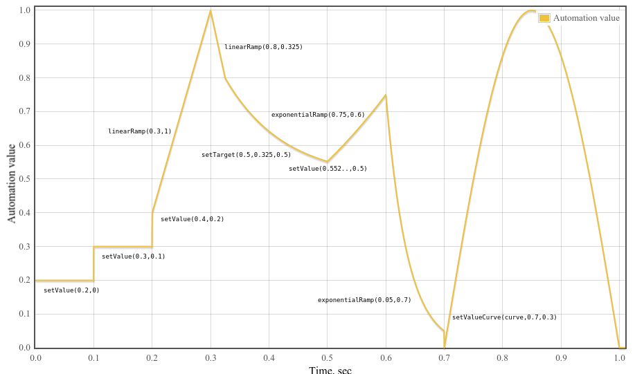
2.6.4
AudioParam Automation Example
Fig. 4
An example of parameter automation.
Example 6
var curveLength =44100;var curve =newFloat32Array(curveLength);for(var i =0; i < curveLength;++i)
curve[i]=Math.sin(Math.PI * i / curveLength);var t0 =0;var t1 =0.1;var t2 =0.2;var t3 =0.3;var t4 =0.325;var t5 =0.5;var t6 =0.6;var t7 =0.7;var t8 =1.0;var timeConstant =0.1;
param.setValueAtTime(0.2, t0);
param.setValueAtTime(0.3, t1);
param.setValueAtTime(0.4, t2);
param.linearRampToValueAtTime(1, t3);
param.linearRampToValueAtTime(0.8, t4);
param.setTargetAtTime(.5, t4, timeConstant);// Compute where the setTargetAtTime will be at time t5 so we can make// the following exponential start at the right point so there's no// jump discontinuity. From the spec, we have// v(t) = 0.5 + (0.8 - 0.5)*exp(-(t-t4)/timeConstant)// Thus v(t5) = 0.5 + (0.8 - 0.5)*exp(-(t5-t4)/timeConstant)
param.setValueAtTime(0.5+(0.8-0.5)*Math.exp(-(t5 - t4)/timeConstant), t5);
param.exponentialRampToValueAtTime(0.75, t6);
param.exponentialRampToValueAtTime(0.05, t7);
param.setValueCurveAtTime(curve, t7, t8 - t7);
2.7
The GainNode Interface
Changing the gain of an audio signal is a fundamental operation in
audio applications. The GainNode is one of the building
blocks for creating mixers. This
interface is an AudioNode with a single input and
single output:
Represents the amount of gain to apply. Its default
value is 1 (no gain change). The nominal
minValue is 0, but may be set negative for phase
inversion. The nominal maxValue is 1, but higher
values are allowed (no exception thrown).This parameter is
a-rate
2.8
The DelayNode Interface
A delay-line is a fundamental building block in audio applications.
This interface is an AudioNode with a single
input and single output:
The number of channels of the output always equals the number of
channels of the input.
It delays the incoming audio signal by a certain amount.
Specifically, at each time t, input signal
input(t), delay time delayTime(t) and output signal
output(t), the output will be output(t) = input(t -
delayTime(t)). The default delayTime is 0 seconds
(no delay).
When the number of channels in a DelayNode's input changes
(thus changing the output channel count also), there may be delayed
audio samples which have not yet been output by the node and are part
of its internal state. If these samples were received earlier with a
different channel count, they must be upmixed or downmixed before
being combined with newly received input so that all internal
delay-line mixing takes place using the single prevailing channel
layout.
An AudioParam object representing the amount
of delay (in seconds) to apply. Its default value is
0 (no delay). The minimum value is 0 and the maximum value is
determined by the maxDelayTime argument to the
AudioContext method createDelay.
If DelayNode is part of a cycle, then
the value of the delayTime attribute is
clamped to a minimum of 128 frames (one block).
This interface represents a memory-resident audio asset (for one-shot
sounds and other short audio clips). Its format is non-interleaved
IEEE 32-bit linear PCM with a nominal range of -1 -> +1. It can
contain one or more channels. Typically, it would be expected that
the length of the PCM data would be fairly short (usually somewhat
less than a minute). For longer sounds, such as music soundtracks,
streaming should be used with the audio element and
MediaElementAudioSourceNode.
The sample-rate for the PCM audio data in samples per second.
2.9.2 Methods
copyFromChannel
The copyFromChannel method copies the samples from the
specified channel of the AudioBuffer to the
destination array.
Parameter
Type
Nullable
Optional
Description
destination
Float32Array
✘
✘
The array the channel data will be copied to.
channelNumber
unsigned long
✘
✘
The index of the channel to copy the data from. If
channelNumber is greater or equal than the number
of channel of the AudioBuffer, an
IndexSizeErrorMUST be thrown.
startInChannel
unsigned long = 0
✘
✔
An optional offset to copy the data from. If
startInChannel is greater than the
length of the AudioBuffer, an
IndexSizeErrorMUST be thrown.
Return type: void
copyToChannel
The copyToChannel method copies the samples to the
specified channel of the AudioBuffer, from the
source array.
Parameter
Type
Nullable
Optional
Description
source
Float32Array
✘
✘
The array the channel data will be copied from.
channelNumber
unsigned long
✘
✘
The index of the channel to copy the data to. If
channelNumber is greater or equal than the number
of channel of the AudioBuffer, an
IndexSizeErrorMUST be thrown.
startInChannel
unsigned long = 0
✘
✔
An optional offset to copy the data to. If
startInChannel is greater than the
length of the AudioBuffer, an
IndexSizeErrorMUST be thrown.
Return type: void
getChannelData
Returns the Float32Array representing the PCM audio
data for the specific channel.
Parameter
Type
Nullable
Optional
Description
channel
unsigned long
✘
✘
This parameter is an index representing the particular channel
to get data for. An index value of 0 represents the first
channel. This index value MUST be less than
numberOfChannels or an IndexSizeError exception
MUST be thrown.
Return type: Float32Array
Note
The methods copyToChannel and
copyFromChannel can be used to fill part of an array by
passing in a Float32Array that's a view onto the larger
array. When reading data from an AudioBuffer's channels, and
the data can be processed in chunks, copyFromChannel
should be preferred to calling getChannelData and
accessing the resulting array, because it may avoid unnecessary
memory allocation and copying.
An internal operation acquire the
contents of an AudioBuffer is invoked when the
contents of an AudioBuffer are needed by some API
implementation. This operation returns immutable channel data to the
invoker.
When an acquire the content
operation occurs on an AudioBuffer, run the following steps:
If any of the AudioBuffer's ArrayBuffer have
been neutered, abort these steps, and return a zero-length channel
data buffers to the invoker.
Neuter all ArrayBuffers for arrays previously
returned by getChannelData on this AudioBuffer.
Retain the underlying data buffers from those
ArrayBuffers and return references to them to the
invoker.
Attach ArrayBuffers containing copies of the data to
the AudioBuffer, to be returned by the next call to
getChannelData.
This means that copyToChannel cannot be used to change
the content of an AudioBuffer currently in use by an
AudioNode that has acquired the content of an AudioBuffer,
since the AudioNode will continue to use the data previously
acquired.
2.10
The AudioBufferSourceNode Interface
This interface represents an audio source from an in-memory audio
asset in an AudioBuffer. It is useful for playing audio
assets which require a high degree of scheduling flexibility, for
instance, playing back in rhythmically-perfect ways. If
sample-accurate playback of network- or disk-backed assets is
required, an implementer should use AudioWorker
to implement playback.
The start() method is used to schedule when sound playback will
happen. The start() method may not be issued multiple times. The
playback will stop automatically when the buffer's audio data has
been completely played (if the loop attribute is false),
or when the stop() method has been called and the specified time has
been reached. Please see more details in the start() and stop()
description.
  numberOfInputs  : 0
  numberOfOutputs : 1
The number of channels of the output always equals the number of
channels of the AudioBuffer assigned to the .buffer attribute, or is
one channel of silence if .buffer is NULL.
An aditional parameter to modulate the speed at which is rendered
the audio stream. Its default value is 0. Its nominal range is
[-1200; 1200]. This parameter is k-rate.
loop of type boolean
Indicates if the audio data should play in a loop. The default
value is false. If loop is dynamically modified during
playback, the new value will take effect on the next processing
block of audio.
loopEnd of type double
An optional value in seconds where looping should end if the
loop attribute is true. Its value is exclusive of the
content of the loop: the sample frames comprising the loop run from
the values loopStart to
loopEnd-(1.0/sampleRate). Its default
value is 0, and it may usefully be set to any value
between 0 and the duration of the buffer. If loopEnd
is less than 0, looping will end at 0. If loopEnd is
greater than the duration of the buffer, looping will end at the
end of the buffer. This attribute is converted to an exact sample
frame offset within the buffer by multiplying by the buffer's
sample rate and rounding to the nearest integer value. Thus its
behavior is independent of the value of the playbackRate
parameter.
loopStart of type double
An optional value in seconds where looping should begin if the
loop attribute is true. Its default value
is 0, and it may usefully be set to any value between 0 and the
duration of the buffer. If loopStart is less than 0,
looping will begin at 0. If loopStart is greater than
the duration of the buffer, looping will begin at the end of the
buffer. This attribute is converted to an exact sample frame offset
within the buffer by multiplying by the buffer's sample rate and
rounding to the nearest integer value. Thus its behavior is
independent of the value of the playbackRate
parameter.
onended of type EventHandler
A property used to set the EventHandler (described in
HTML[HTML]) for the ended event that is dispatched to
AudioBufferSourceNode node types. When the
playback of the buffer for an
AudioBufferSourceNode is finished, an event of
type Event (described in HTML
[HTML]) will be dispatched to the event handler.
The speed at which to render the audio stream. Its default
value is 1. This parameter is k-rate.
2.10.2 Methods
start
Schedules a sound to playback at an exact time. start
may only be called one time and must be called before
stop is called or an InvalidStateError exception MUST
be thrown.
Parameter
Type
Nullable
Optional
Description
when
double = 0
✘
✔
The when parameter describes at what time
(in seconds) the sound should start playing. It is in the same
time coordinate system as the
AudioContext's currentTime attribute.
If 0 is passed in for this value or if the value is less than
currentTime, then the sound will start playing
immediately. A TypeError exception MUST be thrown if
when is negative.
offset
double = 0
✘
✔
The offset parameter describes the
offset time in the buffer (in seconds) where playback will
begin. If 0 is passed in for this value, then playback will
start from the beginning of the buffer. A TypeError exception
MUST be thrown if offset is negative. If
offset is greater than loopEnd,
playback will begin at loopEnd (and immediately
loop to loopStart). This parameter is converted to
an exact sample frame offset within the buffer by multiplying
by the buffer's sample rate and rounding to the nearest integer
value. Thus its behavior is independent of the value of the
playbackRate
parameter.
duration
double
✘
✔
The duration parameter describes the
duration of the portion (in seconds) to be played. If this
parameter is not passed, the duration will be equal to the
total duration of the AudioBuffer minus the offset
parameter. Thus if neither offset nor
duration are specified then the implied duration
is the total duration of the AudioBuffer. An TypeError
exception MUST be thrown if duration is negative.
Return type: void
stop
Schedules a sound to stop playback at an exact time.
Parameter
Type
Nullable
Optional
Description
when
double = 0
✘
✔
The when parameter describes at what time
(in seconds) the sound should stop playing. It is in the same
time coordinate system as the
AudioContext's currentTime attribute.
If 0 is passed in for this value or if the value is less than
currentTime, then the sound will stop
playing immediately. A TypeError exception MUST be thrown if
when is negative. If stop is called
again after already have been called, the last invocation will
be the only one applied; stop times set by previous calls will
not be applied, unless the buffer has already stopped prior to
any subsequent calls. If the buffer has already stopped,
further calls to stop will have no effect. If a
stop time is reached prior to the scheduled start time, the
sound will not play.
Return type: void
Both playbackRate and detune are
k-rate parameters and are used together to determine a
computedPlaybackRate value:
This MUST be implemented by resampling the input data using
a resampling ratio of 1 / computedPlaybackRate, hence
changing both the pitch and speed of the audio.
2.10.3
Looping
If the loop attribute is true when
start() is called, then playback will continue
indefinitely until stop() is called and the stop time
is reached. We'll call this "loop" mode. Playback always starts at
the point in the buffer indicated by the offset
argument of start(), and in loop mode will
continue playing until it reaches the actualLoopEnd
position in the buffer (or the end of the buffer), at which point
it will wrap back around to the actualLoopStart position
in the buffer, and continue playing according to this pattern.
In loop mode then the actual loop points are
calculated as follows from the loopStart and
loopEnd attributes:
Note that the default values for
loopStart and loopEnd are both 0, which
indicates that looping should occur from the very start to the very
end of the buffer.
Please note that as a low-level implementation detail, the
AudioBuffer is at a specific sample-rate (usually the same as the
AudioContext sample-rate), and that the loop
times (in seconds) must be converted to the appropriate
sample-frame positions in the buffer according to this sample-rate.
When scheduling the beginning and the end of playback using the
start() and stop() methods, the resulting
start or stop time MUST be rounded to the nearest sample-frame in
the sample rate of the AudioContext. That is,
no sub-sample scheduling is possible.
2.11
The MediaElementAudioSourceNode Interface
This interface represents an audio source from an audio
or video element.
  numberOfInputs  : 0
  numberOfOutputs : 1
The number of channels of the output corresponds to the number of
channels of the media referenced by the
HTMLMediaElement. Thus, changes to the media element's
.src attribute can change the number of channels output by this node.
If the .src attribute is not set, then the number of channels output
will be one silent channel.
The number of channels of the single output equals the number of
channels of the audio referenced by the HTMLMediaElement
passed in as the argument to createMediaElementSource(),
or is 1 if the HTMLMediaElement has no audio.
The HTMLMediaElement must behave in an identical fashion
after the MediaElementAudioSourceNode has been created,
except that the rendered audio will no longer be heard
directly, but instead will be heard as a consequence of the
MediaElementAudioSourceNode being connected through the
routing graph. Thus pausing, seeking, volume, src
attribute changes, and other aspects of the
HTMLMediaElement must behave as they normally would if
not used with a MediaElementAudioSourceNode.
Example 7
var mediaElement = document.getElementById('mediaElementID');var sourceNode = context.createMediaElementSource(mediaElement);
sourceNode.connect(filterNode);
2.11.1
Security with MediaElementAudioSourceNode and cross-origin
resources
HTMLMediaElement allows the playback of cross-origin
resources. Because Web Audio can allows one to inspect the content
of the resource (e.g. using a MediaElementAudioSourceNode,
and a ScriptProcessorNode to read the samples), information
leakage can occur if scripts from one
origin inspect the content of a resource from another
origin.
To prevent this, a MediaElementAudioSourceNodeMUST output
silence instead of the normal output of the
HTMLMediaElement if it has been created using an
HTMLMediaElement for which the execution of the
fetch algorithm labeled the resource as
CORS-cross-origin.
2.12
The AudioWorker interface
An AudioWorker object is the main-thread representation of a worker
"thread" that supports processing of audio in Javascript. This
AudioWorker object is a factory that is used to create multiple audio
nodes of the same type; this enables easy sharing of code, program
data and global state across nodes. An AudioWorker can then be used
to create instances of AudioWorkerNode, which is the
main-thread representation of an individual node processed by that
AudioWorker.
These main thread objects cause the instantiation of a processing
context in the audio thread. All audio processing by AudioWorkerNodes
runs in the audio processing thread. This has a few side effects that
bear mentioning: blocking the audio worker's thread can cause
glitches in the audio, and if the audio thread is normally elevated
in thread priority (to reduce glitching possibility), it must be
demoted to normal thread priority (in order to avoid escalating
thread priority of user-supplied script code).
From inside an audio worker script, the Audio Worker factory is
represented by an AudioWorkerGlobalScope object
representing the node's contextual information, and individual audio
nodes created by the factory are represented by
AudioWorkerNodeProcessor objects.
In addition, all AudioWorkerNodes that are created by the same
AudioWorker share an AudioWorkerGlobalScope; this can
allow them to share context and data across nodes (for example,
loading a single instance of a shared database used by the individual
nodes, or sharing context in order to implement oscillator
synchronization).
This array contains descriptors for each of the current parameters
on nodes created by this AudioWorker. This enables users of the
AudioWorker to easily iterate over the AudioParam names and default
values.
2.12.2 Methods
addParameter
Causes a correspondingly-named read-only AudioParam to be
present on any AudioWorkerNodes created (previously or
subsequently) by this AudioWorker, and a
correspondingly-named read-only Float32Array to be present
on the parameters object exposed on the
AudioProcessEvent on subsequent audio processing events
for such nodes. The AudioParam may immediately have its
scheduling methods called, its .value set, or
AudioNodes connected to it.
The name parameter is the name used for the
read-only AudioParam added to the AudioWorkerNode, and the name
used for the read-only Float32Array that will be
present on the parameters object exposed on
subsequent AudioProcessEvents.
The defaultValue parameter is the default
value for the AudioParam's value attribute, as well
as therefore the default value that will appear in the
Float32Array in the worker script (if no other parameter changes
or connections affect the value).
postMessage may be called to send a message to the
AudioWorkerGlobalScope, similar to the algorithm defined by
[Workers].
Parameter
Type
Nullable
Optional
Description
message
any
✘
✘
transfer
sequence<Transferable>
✘
✔
Return type: void
removeParameter
Removes a previously-added parameter named name from
all AudioWorkerNodes associated with this
AudioWorker and its AudioWorkerGlobalScope. This
will also remove the correspondingly-named read-only
AudioParam from the AudioWorkerNode, and will
remove the correspondingly-named read-only Float32Arrays
from the AudioProcessEvent's
parameters member on subsequent audio
processing events. A NotFoundError exception must be thrown if no
parameter with that name exists on this AudioWorker.
The name parameter identifies the parameter to be
removed.
Parameter
Type
Nullable
Optional
Description
name
DOMString
✘
✘
Return type: void
terminate
The terminate() method, when invoked, must cause the cessation of
any AudioProcessEvents being dispatched inside the
AudioWorker's associated AudioWorkerGlobalScope. It will
also cause all associated AudioWorkerNodes to cease processing, and
will cause the destruction of the worker's context. In practical
terms, this means all nodes created from this AudioWorker will
disconnect themselves, and will cease performing any useful
functions.
No parameters.
Return type: void
Note that AudioWorkerNode objects will also have read-only
AudioParam objects for each named parameter added via the
addParameter method. As this is dynamic, it cannot be
captured in IDL.
As the AudioWorker interface inherits from
Worker, AudioWorkers must implement the
Worker interface for communication with the audio worker
script.
2.12.3
The AudioWorkerNode Interface
This interface represents an AudioNode which
interacts with a Worker thread to generate, process,
or analyse audio directly. The user creates a separate audio
processing worker script, which is hosted inside the
AudioWorkerGlobalScope and runs inside the audio processing thread,
rather than the main UI thread. The AudioWorkerNode represents the
processing node in the main processing thread's node graph; the
AudioWorkerGlobalScope represents the context in which the user's
audio processing script is run.
Nota bene that if the Web Audio implementation normally runs audio
process at higher than normal thread priority, utilizing
AudioWorkerNodes may cause demotion of the priority of the audio
thread (since user scripts cannot be run with higher than normal
priority).
The number of input and output channels specified in the
createAudioWorkerNode() call determines the initial number of input
and output channels (and the number of channels present for each
input and output in the AudioBuffers passed to the AudioProcess
event handler inside the AudioWorkerGlobalScope). It is
invalid for both numberOfInputChannels
and numberOfOutputChannels
to be zero.
Example usage:
var bitcrusherFactory = context.createAudioWorker("bitcrusher.js");var bitcrusherNode = bitcrusherFactory.createNode();
The onmessage handler is called whenever the
AudioWorkerNodeProcessor posts a node message back to the main
thread.
2.12.3.2 Methods
postMessage
postMessage may be called to send a message to the
AudioWorkerNodeProcessor, via the algorithm defined by the
Worker specification. Note that this is different from
calling postMessage() on the AudioWorker itself, as that would
affect the AudioWorkerGlobalScope.
Parameter
Type
Nullable
Optional
Description
message
any
✘
✘
transfer
sequence<Transferable>
✘
✔
Return type: void
Note that AudioWorkerNode objects will also have read-only
AudioParam objects for each named parameter added via the
addParameter method on the AudioWorker. As this is
dynamic, it cannot be captured here in IDL.
2.12.4
The AudioWorkerParamDescriptor Interface
This interface represents the description of an AudioWorkerNode
AudioParam - in short, its name and default value. This enables
easy iteration over the AudioParams from an AudioWorkerGlobalScope
(which does not have an instance of those AudioParams).
This interface is a DedicatedWorkerGlobalScope-derived
object representing the context in which an audio processing script
is run; it is designed to enable the generation, processing, and
analysis of audio data directly using JavaScript in a Worker
thread, with shared context between multiple instances of audio
nodes. This facilitates nodes that may have substantial shared
data, e.g. a convolution node.
-
The AudioWorkerGlobalScope handles - audioprocess events dispatched -
synchronously to process audio frame blocks for nodes created by
this worker. - audioprocess events are
only - dispatched for nodes that have at least one input - or one
output connected. TODO: should this be true?
A property used to set the EventHandler (described
in [HTML]) for the audioprocess event that
is dispatched to AudioWorkerGlobalScope to
process audio while the associated nodes are connected (to at
least one input or output). An event of type
AudioProcessEvent will be dispatched to the
event handler.
onnodecreate of type EventHandler
A property used to set the EventHandler (described
in [HTML]) for the nodecreate event that is
dispatched to AudioWorkerGlobalScope when a
new AudioWorkerNode has been created. This
enables the scope to do node-level initialization of the
AudioNodeProcessor object. An event of type
AudioWorkerNodeCreationEvent will be
dispatched to the event handler.
This array contains descriptors for each of the current
parameters on nodes created in this AudioWorkerGlobalScope. This
enables audio worker implementations to easily iterate over the
AudioParam names and default values.
sampleRate of type float, readonly
The sample rate of the host AudioContext (since inside the
Worker scope, the user will not have direct access
to the AudioContext.
2.12.5.2 Methods
addParameter
Causes a correspondingly-named read-only AudioParam to
be present on previously-created and subsequently-created
AudioWorkerNodes created by this factory, and a
correspondingly-named read-only Float32Array to be
present on the parameters object exposed on
the AudioProcessEvent on subsequent audio processing
events for nodes created from this factory.
It is purposeful that AudioParams can be added (or removed)
from an Audio Worker from either the main thread or the worker
script; this enables immediate creation of worker-based nodes
and their prototypes, but also enables packaging an entire
worker including its AudioParam configuration into a single
script. It is recommended that nodes be used only after the
AudioWorkerNode's oninitialized has been called, in order to
allow the worker script to configure the node.
The name parameter is the name used for the
read-only AudioParam added to the AudioWorkerNode, and the name
used for the read-only Float32Array that will be
present on the parameters object exposed on
subsequent AudioProcessEvents.
The defaultValue parameter is
the default value for the AudioParam's value
attribute, as well as therefore the default value that will
appear in the Float32Array in the worker script (if no other
parameter changes or connections affect the value).
Removes a previously-added parameter named name
from nodes processed by this factory. This will also remove the
correspondingly-named read-only AudioParam from the
AudioWorkerNode, and will remove the
correspondingly-named read-only Float32Array from the
AudioProcessEvent's parameters
member on subsequent audio processing events. A NotFoundError
exception MUST be thrown if no parameter with that name exists
on this node.
The name parameter identifies the parameter to be
removed.
Parameter
Type
Nullable
Optional
Description
name
DOMString
✘
✘
Return type: void
2.12.6
The AudioWorkerNodeProcessor Interface
An object supporting this interface represents each individual node
instantiated in an AudioWorkerGlobalScope; it
is designed to manage the data for an individual node. Shared
context between multiple instances of audio nodes is accessible
from the AudioWorkerGlobalScope; this object represents the
individual node and can be used for data storage or main-thread
communication.
The onmessage handler is called whenever the AudioWorkerNode
posts a node message back to the audio thread.
2.12.6.2 Methods
postMessage
postMessage may be called to send a message to the
AudioWorkerNode, via the algorithm defined by the
Worker specification. Note that this is different from
calling postMessage() on the AudioWorker itself, as that would
dispatch to the AudioWorkerGlobalScope.
Parameter
Type
Nullable
Optional
Description
message
any
✘
✘
transfer
sequence<Transferable>
✘
✔
Return type: void
2.12.7
Audio Worker Examples
This section is non-normative.
2.12.7.1
A Bitcrusher Node
Bitcrushing is a mechanism by which the audio quality of an audio
stream is reduced - both by quantizing the value (simulating
lower bit-depth in integer-based audio), and by quantizing in
time (simulating a lower digital sample rate). This example shows
how to use AudioParams (in this case, treated as a-rate) inside
an AudioWorker.
Main file javascript
var bitcrusherFactory =null;
audioContext.createAudioWorker("bitcrusher_worker.js").then(function(factory){// cache 'factory' in case you want to create more nodes!
bitcrusherFactory = factory;var bitcrusherNode = factory.createNode();
bitcrusherNode.bits.setValueAtTime(8,0);
bitcrusherNode.connect(output);
input.connect(bitcrusherNode);});
2.12.7.2
TODO: fix up this example. A Volume Meter and Clip Detector
Another common need is a clip-detecting volume meter. This
example shows how to communicate basic parameters (that do not
need AudioParam scheduling) across to a Worker, as well as
communicating data back to the main thread. This node does not
use any output.
Main file javascript
function setupNodeMessaging(node){// This handles communication back from the volume meter
node.onmessage =function(event){if(event.data instanceof Object){if(event.data.hasOwnProperty("clip")this.clip =event.data.clip;if(event.data.hasOwnProperty("volume")this.volume =event.data.volume;}}// Set up some default configuration parameters
node.postMessage({"smoothing":0.9,// Smoothing parameter"clipLevel":0.9,// Level to consider "clipping""clipLag":750,// How long to keep "clipping" lit up after clip (ms)"updating":100// How frequently to update volume and clip param (ms)});// Set up volume and clip attributes. These will be updated by our onmessage.
node.volume =0;
node.clip =false;}var vuNode =null;
audioContext.createAudioWorker("vu_meter_worker.js").then(function(factory){// cache 'factory' in case you want to create more nodes!
vuFactory = factory;
vuNode = factory.createNode([1],[]);// we don't need an output, and let's force to mono
setupNodeMessaging(vuNode);});
window.requestAnimationFrame(function(timestamp){if(vuNode){// Draw a bar based on vuNode.volume and vuNode.clip}});
vu_meter_worker.js
// Custom parameter - number of bits to crush down to - default 8this.addParameter("bits",8);// Custom parameter - frequency reduction, 0-1, default 0.5this.addParameter("frequencyReduction",0.5);
onnodecreate=function(e){
e.node.timeToNextUpdate =0.1* sampleRate;
e.node.smoothing =0.5;
e.node.clipLevel =0.95;
e.node.clipLag =1;
e.node.updatingInterval =150;// This just handles setting attribute values
e.node.onmessage =function(event){if(event.data instanceof Object){if(event.data.hasOwnProperty("smoothing")this.smoothing =event.data.smoothing;if(event.data.hasOwnProperty("clipLevel")this.clipLevel =event.data.clipLevel;if(event.data.hasOwnProperty("clipLag")this.clipLag =event.data.clipLag /1000;// convert to secondsif(event.data.hasOwnProperty("updating")// convert to samplesthis.updatingInterval =event.data.updating * sampleRate /1000;}};}
onaudioprocess =function(event){var buf =event.inputs[0][0];// Node forces monovar bufLength = buf.length;var sum =0;var x;// Do a root-mean-square on the samples: sum up the squares...for(var i=0; i<bufLength; i++){
x = buf[i];if(Math.abs(x)>=event.node.clipLevel){event.node.clipping =true;event.node.unsentClip =true;// Make sure, for every clip, we send a message.event.node.lastClip =event.playbackTime +(i/sampleRate);}
sum += x * x;}// ... then take the square root of the sum.var rms =Math.sqrt(sum / bufLength);// Now smooth this out with the smoothing factor applied// to the previous sample - take the max here because we// want "fast attack, slow release."event.node.volume =Math.max(rms,event.node.volume*event.node.smoothing);if(event.node.clipping &&(!event.node.unsentClip)&&(event.playbackTime >(this.lastClip + clipLag)))event.node.clipping =false;// How long has it been since our last update?event.node.timeToNextUpdate -=event.node.last;if(event.node.timeToNextUpdate<0){event.node.timeToNextUpdate =event.node.updatingInterval;event.node.postMessage({"volume":event.node.volume,"clip":event.node.clipping });event.node.unsentClip =false;}};
2.12.7.3
Reimplementing ChannelMerger
This worker shows how to merge inputs into a single output
channel.
Main file javascript
var mergerNode = audioContext.createAudioWorker("merger_worker.js",[1,1,1,1,1,1],[6]);
var mergerFactory =null;
audioContext.createAudioWorker("merger_worker.js").then(function(factory){// cache 'factory' in case you want to create more nodes!
mergerFactory = factory;var merger6channelNode = factory.createNode([1,1,1,1,1,1],[6]);// connect inputs and outputs here});
2.13
The ScriptProcessorNode Interface - DEPRECATED
This section is non-normative.
This interface is an AudioNode which can
generate, process, or analyse audio directly using JavaScript. This
node type is deprecated, to be replaced by the
AudioWorkerNode; this text is only here for informative
purposes until implementations remove this node type.
The channelCountMode cannot be changed from "explicit"
and the channelCount cannot be changed. An attempt to
change either of these MUST throw an InvalidStateError exception.
The ScriptProcessorNode is constructed with a
bufferSize which must be one of the following values: 256,
512, 1024, 2048, 4096, 8192, 16384. This value controls how
frequently the audioprocess event
is dispatched and how many sample-frames need to be processed each
call. audioprocess
events are only dispatched if the
ScriptProcessorNode has at least one input or one
output connected. Lower numbers for bufferSize will result in
a lower (better) latency. Higher numbers will
be necessary to avoid audio breakup and glitches. This value will be picked by the
implementation if the bufferSize argument to
createScriptProcessor is not passed in, or is set to 0.
numberOfInputChannels and
numberOfOutputChannels determine the number of input and
output channels. It is invalid for both
numberOfInputChannels and
numberOfOutputChannels to be zero.
var node = context.createScriptProcessor(bufferSize, numberOfInputChannels, numberOfOutputChannels);
The size of the buffer (in sample-frames) which needs to be
processed each time onaudioprocess is called. Legal
values are (256, 512, 1024, 2048, 4096, 8192, 16384).
This is an Event object which is dispatched to
AudioWorkerGlobalScope objects when a new node
instance is created. This allows AudioWorkers to initialize any
node-local data (e.g. allocating a delay or initializing local
variables).
The new node being created. Any node-local data storage (e.g., the
buffer for a delay node) should be created on this object.
outputs of type Array, readonly
An array of channelCounts for the outputs.
2.15
The AudioProcessEvent Interface
This is an Event object which is dispatched to
AudioWorkerGlobalScope objects to perform
processing.
The event handler processes audio from the input (if any) by
accessing the audio data from the inputBuffers
attribute. The audio data which is the result of the processing (or
the synthesized data if there are no inputs) is then placed into the
outputBuffers.
inputs of type array of array of Float32Array, readonly
A readonly Array of Arrays of Float32Arrays. The top-level Array
is organized by input; each input may contain multiple channels;
each channel contains a Float32Array of sample data. The initial
size of the channel array will be determined by the number of
channels specified for that input in the createAudioWorkerNode()
method. However, an onprocess handler may alter this number of
channels in the input dynamically, either by adding a
Float32Array of blocksize length (128) or by reducing the Array
(by reducing the Array.length or by using Array.pop() or
Array.slice(). The event object, the Array and the Float32Arrays
will be reused by the processing system, in order to minimize
memory churn.
Any reordering performed on the Array for an input will not
reorganize the connections to the channels for subsequent events.
The node to which this processing event is being dispatched. Any
node-local data storage (e.g., the buffer for a delay node) should
be maintained on this object.
outputs of type array of array of Float32Array, readonly
A readonly Array of Arrays of Float32Arrays. The top-level Array
is organized by output; each output may contain multiple
channels; each channel contains a Float32Array of sample data.
The initial size of the channel array will be determined by the
number of channels specified for that output in the
createAudioWorkerNode() method. However, an onprocess handler may
alter this number of channels in the output dynamically, either
by adding a Float32Array of blocksize length (128) or by reducing
the Array (by reducing the Array.length or by using Array.pop()
or Array.slice(). The event object, the Array and the
Float32Arrays will be reused by the processing system, in order
to minimize memory churn.
Any reordering performed on the Array for an output will not
reorganize the connections to the channels for subsequent events.
parameters of type object, readonly
This object attribute exposes a correspondingly-named read-only
Float32Array for each parameter that has been added via
addParameter. As this is dynamic, this cannot be captured in
IDL. The length of this Float32Array will correspond to the length
of the inputBuffer. The contents of this Float32Array will be the
values to be used for the AudioParam at the corresponding points in
time. It is expected that this Float32Array will be reused by the
audio engine.
playbackTime of type double, readonly
The starting time of the block of audio being processed in response
to this event. By definition this will be equal to the value of
BaseAudioContext's currentTime attribute that
was most recently observable in the control thread.
2.16
The AudioProcessingEvent Interface - DEPRECATED
This section is non-normative.
This is an Event object which is dispatched to
ScriptProcessorNode nodes. It will be removed
when the ScriptProcessorNode is removed, as the replacement
AudioWorker uses the AudioProcessEvent.
The event handler processes audio from the input (if any) by
accessing the audio data from the inputBuffer attribute.
The audio data which is the result of the processing (or the
synthesized data if there are no inputs) is then placed into the
outputBuffer.
An AudioBuffer containing the input audio data. It will have a
number of channels equal to the numberOfInputChannels
parameter of the createScriptProcessor() method. This AudioBuffer
is only valid while in the scope of the onaudioprocess
function. Its values will be meaningless outside of this scope.
An AudioBuffer where the output audio data should be written. It
will have a number of channels equal to the
numberOfOutputChannels parameter of the
createScriptProcessor() method. Script code within the scope of the
onaudioprocess function is expected to modify the
Float32Array arrays representing channel data in this
AudioBuffer. Any script modifications to this AudioBuffer outside
of this scope will not produce any audible effects.
playbackTime of type double, readonly
The time when the audio will be played in the same time coordinate
system as the AudioContext's currentTime.
2.17
The PannerNode Interface
This interface represents a processing node which positions / spatializes an incoming audio
stream in three-dimensional space. The spatialization is in relation
to the AudioContext's AudioListener
(listener attribute).
The input of this node is either mono (1 channel) or stereo (2
channels) and cannot be increased. Connections from nodes with fewer
or more channels will be up-mixed or down-mixed
appropriately, but a NotSupportedError MUST be thrown if an
attempt is made to set channelCount to a value greater than 2 or if
channelCountMode is set to "max".
The output of this node is hard-coded to stereo (2 channels) and
cannot be configured.
The PanningModelType enum determines which
spatialization algorithm will be used to position the audio in 3D
space. The default is "equalpower".
A simple and efficient spatialization algorithm using equal-power
panning.
HRTF
A higher quality spatialization algorithm using a convolution with
measured impulse responses from human subjects. This panning method
renders stereo output.
The DistanceModelType enum determines which
algorithm will be used to reduce the volume of an audio source as it
moves away from the listener. The default is "inverse".
In the description of each distance model below, let \(d\) be the
distance between the listener and the panner; \(d_{ref}\) be the
value of the refDistance attribute; \(d_{max}\) be the
value of the maxDistance attribute; and \(f\) be the
value of the rolloffFactor attribute.
A parameter for directional audio sources, this is an angle, in
degrees, inside of which there will be no volume reduction. The
default value is 360, and the value is used modulo 360.
coneOuterAngle of type float
A parameter for directional audio sources, this is an angle, in
degrees, outside of which the volume will be reduced to a constant
value of coneOuterGain. The default value is
360 and the value is used modulo 360.
coneOuterGain of type float
A parameter for directional audio sources, this is the gain outside
of the coneOuterAngle. The default value is 0.
It is a linear value (not dB) in the range [0, 1]. An
InvalidStateError MUST be thrown if the parameter is outside this
range.
Specifies the panning model used by this
PannerNode. Defaults to
"equalpower".
refDistance of type float
A reference distance for reducing volume as source move further
from the listener. The default value is 1.
rolloffFactor of type float
Describes how quickly the volume is reduced as source moves away
from listener. The default value is 1.
2.17.2 Methods
setOrientation
Describes which direction the audio source is pointing in the 3D
cartesian coordinate space. Depending on how directional the
sound is (controlled by the cone attributes), a sound
pointing away from the listener can be very quiet or completely
silent.
The x, y, z parameters represent a direction vector
in 3D space.
The default value is (1,0,0)
Parameter
Type
Nullable
Optional
Description
x
float
✘
✘
y
float
✘
✘
z
float
✘
✘
Return type: void
setPosition
Sets the position of the audio source relative to the
listener attribute. A 3D cartesian coordinate
system is used.
The x, y, z parameters represent the coordinates in
3D space.
The default value is (0,0,0)
Parameter
Type
Nullable
Optional
Description
x
float
✘
✘
y
float
✘
✘
z
float
✘
✘
Return type: void
setVelocity
Sets the velocity vector of the audio source. This vector
controls both the direction of travel and the speed in 3D space.
This velocity relative to the listener's velocity is used to
determine how much doppler shift (pitch change) to apply. The
units used for this vector is meters / second and is
independent of the units used for position and orientation
vectors.
The x, y, z parameters describe a direction vector
indicating direction of travel and intensity.
This interface is DEPRECATED, as it will be replaced by the
SpatialListener. This interface represents the
position and orientation of the person listening to the audio scene.
All PannerNode objects spatialize in relation to
the BaseAudioContext's listener. See the Spatialization/Panning section for more
details about spatialization.
Describes which direction the listener is pointing in the 3D
cartesian coordinate space. Both a front vector and an
up vector are provided. In simple human terms, the
front vector represents which direction the person's nose
is pointing. The up vector represents the direction the
top of a person's head is pointing. These values are expected to
be linearly independent (at right angles to each other). For
normative requirements of how these values are to be interpreted,
see the spatialization section.
The x, y, z parameters represent a front
direction vector in 3D space, with the default value being
(0,0,-1).
The xUp, yUp, zUp parameters represent an up
direction vector in 3D space, with the default value being
(0,1,0).
Parameter
Type
Nullable
Optional
Description
x
float
✘
✘
y
float
✘
✘
z
float
✘
✘
xUp
float
✘
✘
yUp
float
✘
✘
zUp
float
✘
✘
Return type: void
setPosition
Sets the position of the listener in a 3D cartesian coordinate
space. PannerNode objects use this position
relative to individual audio sources for spatialization.
The x, y, z parameters represent the coordinates in
3D space.
The default value is (0,0,0)
Parameter
Type
Nullable
Optional
Description
x
float
✘
✘
y
float
✘
✘
z
float
✘
✘
Return type: void
2.19
The SpatialPannerNode Interface
This interface represents a processing node which positions an incoming audio stream in
three-dimensional space. The spatialization is in relation to the
AudioContext's SpatialListener
(listener attribute).
It should be explicitly noticed that the auditory effects of this
spatialization may not work well unless the SpatialPanner is directly
connected to the destination node; subsequent processing (after the
SpatialPanner, before the destination) may disrupt the effects.
The input of this node is either mono (1 channel) or stereo (2
channels) and cannot be increased. Connections from nodes with more
channels will be up-mixed or down-mixed
appropriately, but a NotSupportedError MUST be thrown if an
attempt is made to set channelCount to a value greater than 2 or if
channelCountMode is set to "max". The output of this node will be
stereo (2 channels) and currently cannot be configured.
The PanningModelType enum determines which
spatialization algorithm will be used to position the audio in 3D
space. The default is "equal-power".
A simple and efficient spatialization algorithm using equal-power
panning.
HRTF
A higher quality spatialization algorithm using a convolution with
measured impulse responses from human subjects. This panning method
renders stereo output.
The DistanceModelType enum determines which
algorithm will be used to reduce the volume of an audio source as it
moves away from the listener. The default is "inverse".
A parameter for directional audio sources, this is an angle, in
degrees, inside of which there will be no volume reduction. The
default value is 360.
coneOuterAngle of type float
A parameter for directional audio sources, this is an angle, in
degrees, outside of which the volume will be reduced to a constant
value of coneOuterGain. The default value is
360.
coneOuterGain of type float
A parameter for directional audio sources, this is the amount of
volume reduction outside of the coneOuterAngle.
The default value is 0.
Describes the y component of the vector of the direction the audio
source is pointing in 3D cartesian coordinate space. The default
value is 0. This parameter is a-rate.
Describes the Z component of the vector of the direction the audio
source is pointing in 3D cartesian coordinate space. The default
value is 0. This parameter is a-rate.
Sets the z coordinate position of the audio source in a 3D
Cartesian system. The default value is 0. This parameter is a-rate.
refDistance of type float
A reference distance for reducing volume as source move further
from the listener. The default value is 1.
rolloffFactor of type float
Describes how quickly the volume is reduced as source moves away
from listener. The default value is 1.
2.20
The SpatialListener Interface
This interface represents the position and orientation of the person
listening to the audio scene. All
SpatialPannerNode objects spatialize in relation
to the AudioContext's spatialListener.
See the Spatialization/Panning section
for more details about spatialization.
The forwardX, forwardY, forwardZ parameters represent
a direction vector in 3D space. Both a forward vector
and an up vector are used to determine the orientation
of the listener. In simple human terms, the forward
vector represents which direction the person's nose is pointing.
The up vector represents the direction the top of a
person's head is pointing. These values are expected to be linearly
independent (at right angles to each other), and unpredictable
behavior may result if they are not. For normative requirements of
how these values are to be interpreted, see the spatialization section.
Sets the y coordinate component of the forward direction the
listener is pointing in 3D Cartesian coordinate space. The default
value is 0. This parameter is a-rate.
Sets the z coordinate component of the forward direction the
listener is pointing in 3D Cartesian coordinate space. The default
value is 0. This parameter is a-rate.
Sets the x coordinate position of the audio listener in a 3D
Cartesian coordinate space. SpatialPannerNode
objects use this position relative to individual audio sources for
spatialization. The default value is 0. This parameter is a-rate.
The upX, upY, upZ parameters represent a direction
vector in 3D space, indicating the direction of "up" to the
listener. For normative requirements of how these values are to be
interpreted, see the spatialization
section.
Sets the y coordinate component of the up direction the listener is
pointing in 3D Cartesian coordinate space. The default value is 0.
This parameter is a-rate.
Sets the z coordinate component of the up direction the listener is
pointing in 3D Cartesian coordinate space. The default value is 0.
This parameter is a-rate.
2.21
The StereoPannerNode Interface
This interface represents a processing node which positions an
incoming audio stream in a stereo image using a low-cost equal-power panning algorithm. This
panning effect is common in positioning audio components in a stereo
stream.
The input of this node is stereo (2 channels) and cannot be
increased. Connections from nodes with fewer or more channels will be
up-mixed or down-mixed
appropriately , but a NotSupportedError will be thrown if an
attempt is made to set channelCount to a value great
than 2 or if channelCountMode is set to
"max".
The output of this node is hard-coded to stereo (2 channels) and
cannot be configured.
The position of the input in the output's stereo image. -1
represents full left, +1 represents full right. Its default value
is 0, and its nominal range is from -1 to 1. This parameter is a
a-rate.
2.21.2
Channel Limitations
This section is non-normative.
Because its processing is constrained by the above definitions,
StereoPannerNode is limited to mixing no more
than 2 channels of audio, and producing exactly 2 channels. It is
possible to use a ChannelSplitterNode,
intermediate processing by a subgraph of
GainNodes and/or other nodes, and recombination
via a ChannelMergerNode to realize arbitrary
approaches to panning and mixing.
2.22
The ConvolverNode Interface
This interface represents a processing node which applies a linear
convolution effect given an impulse response.
The input of this node is either mono (1 channel) or stereo (2
channels) and cannot be increased. Connections from nodes with fewer
or more channels will be up-mixed or down-mixed
appropriately, but a NotSupportedError MUST be thrown if an
attempt is made to set channelCount to a value great than 2 or if
channelCountMode is set to "max".
A mono, stereo, or 4-channel AudioBuffer
containing the (possibly multi-channel) impulse response used by
the ConvolverNode. The AudioBuffer
must have 1, 2, or 4 channels or a NotSupportedError exception MUST
be thrown. This AudioBuffer must be of the same
sample-rate as the AudioContext or a
NotSupportedError exception MUST be thrown. At the time when this
attribute is set, the buffer and the state of the
normalize attribute will be used to configure the
ConvolverNode with this impulse response having
the given normalization. The initial value of this attribute is
null.
normalize of type boolean
Controls whether the impulse response from the buffer will be
scaled by an equal-power normalization when the
buffer atttribute is set. Its default value is
true in order to achieve a more uniform output level
from the convolver when loaded with diverse impulse responses. If
normalize is set to false, then the
convolution will be rendered with no pre-processing/scaling of
the impulse response. Changes to this value do not take effect
until the next time the buffer attribute is set.
If the normalize attribute is false when the
buffer attribute is set then the
ConvolverNode will perform a linear
convolution given the exact impulse response contained within the
buffer.
Otherwise, if the normalize attribute is true when the
buffer attribute is set then the
ConvolverNode will first perform a scaled
RMS-power analysis of the audio data contained within
buffer to calculate a normalizationScale given
this algorithm:
function calculateNormalizationScale(buffer){varGainCalibration=0.00125;varGainCalibrationSampleRate=44100;varMinPower=0.000125;// Normalize by RMS power.var numberOfChannels = buffer.numberOfChannels;var length = buffer.length;var power =0;for(var i =0; i < numberOfChannels; i++){var channelPower =0;var channelData = buffer.getChannelData(i);for(var j =0; j < length; j++){var sample = channelData[j];
channelPower += sample * sample;}
power += channelPower;}
power =Math.sqrt(power /(numberOfChannels * length));// Protect against accidental overload.if(!isFinite(power)|| isNaN(power)|| power <MinPower)
power =MinPower;var scale =1/ power;// Calibrate to make perceived volume same as unprocessed.
scale *=GainCalibration;// Scale depends on sample-rate.if(buffer.sampleRate)
scale *=GainCalibrationSampleRate/ buffer.sampleRate;// True-stereo compensation.if(numberOfChannels ==4)
scale *=0.5;return scale;}
During processing, the ConvolverNode will then take this
calculated normalizationScale value and multiply it by
the result of the linear convolution resulting from processing
the input with the impulse response (represented by the
buffer) to produce the final output. Or any
mathematically equivalent operation may be used, such as
pre-multiplying the input by normalizationScale, or
pre-multiplying a version of the impulse-response by
normalizationScale.
2.22.2
Channel Configurations for Input, Impulse Response and Output
Implementations MUST support the following allowable configurations
of impulse response channels in a ConvolverNode
to achieve various reverb effects with 1 or 2 channels of input.
The first image in the diagram illustrates the general case, where
the source has N input channels, the impulse response has K
channels, and the playback system has M output channels. Because
ConvolverNode is limited to 1 or 2 channels of
input, not every case can be handled.
Single channel convolution operates on a mono audio input, using a
mono impulse response, and generating a mono output. The remaining
images in the diagram illustrate the supported cases for mono and
stereo playback where N and M are 1 or 2 and K is 1, 2, or 4.
Developers desiring more complex and arbitrary matrixing can use a
ChannelSplitterNode, multiple single-channel
ConvolverNodes and a
ChannelMergerNode.
Fig. 5
A graphical representation of supported input and output channel
count possibilities when using a
ConvolverNode.
2.23
The AnalyserNode Interface
This interface represents a node which is able to provide real-time
frequency and time-domain analysis information. The audio stream will
be passed un-processed from input to output.
    numberOfInputs  : 1
    numberOfOutputs : 1    Note that this output may be left unconnected.

    channelCount = 1;
    channelCountMode = "max";
    channelInterpretation = "speakers";
The size of the FFT used for frequency-domain analysis. This must
be a power of two in the range 32 to 32768, otherwise an
IndexSizeError exception MUST be thrown. The default value is 2048.
Note that large FFT sizes can be costly to compute.
frequencyBinCount of type unsigned long, readonly
Half the FFT size.
maxDecibels of type float
maxDecibels is the maximum power value
in the scaling range for the FFT analysis data for conversion to
unsigned byte values. The default value is -30. If the value of
this attribute is set to a value less than or equal to
minDecibels, an IndexSizeError exception MUST
be thrown.
minDecibels of type float
minDecibels is the minimum power value
in the scaling range for the FFT analysis data for conversion to
unsigned byte values. The default value is -100. If the value of
this attribute is set to a value more than or equal to
maxDecibels, an IndexSizeError exception MUST
be thrown.
smoothingTimeConstant of type float
A value from 0 -> 1 where 0 represents no time averaging with
the last analysis frame. The default value is 0.8. If the value of
this attribute is set to a value less than 0 or more than 1, an
IndexSizeError exception MUST be thrown.
2.23.2 Methods
getByteFrequencyData
Copies the current frequency data into the passed unsigned
byte array. If the array has fewer elements than the
frequencyBinCount, the excess elements will
be dropped. If the array has more elements than the
frequencyBinCount, the excess elements will
be ignored.
The values stored in the unsigned byte array are computed in the
following way. Let \(Y[k]\) be the current frequency data
as described in FFT windowing and
smoothing. Then the byte value, \(b[k]\), is
where \(\mbox{dB}_{min}\) is minDecibels and
\(\mbox{dB}_{max}\) is maxDecibels. If
\(b[k]\) lies outside the range of 0 to 255, \(b[k]\) is clipped
to lie in that range.
Parameter
Type
Nullable
Optional
Description
array
Uint8Array
✘
✘
This parameter is where the frequency-domain analysis data will
be copied.
Return type: void
getByteTimeDomainData
Copies the current down-mixed time-domain (waveform) data into
the passed unsigned byte array. If the array has fewer elements
than the value of fftSize, the excess
elements will be dropped. If the array has more elements than
fftSize, the excess elements will be ignored.
The values stored in the unsigned byte array are computed in the
following way. Let \(x[k]\) be the time-domain data. Then the
byte value, \(b[k]\), is
              $$
                b[k] = 128(1 + x[k]).
              $$
If \(b[k]\) lies outside the range 0 to 255, \(b[k]\) is clipped
to lie in that range.
Parameter
Type
Nullable
Optional
Description
array
Uint8Array
✘
✘
This parameter is where the time-domain sample data will be
copied.
Return type: void
getFloatFrequencyData
Copies the current frequency data into the passed
floating-point array. If the array has fewer elements than the
frequencyBinCount, the excess elements will
be dropped. If the array has more elements than the
frequencyBinCount, the excess elements will
be ignored.
The frequency data are in dB units.
Parameter
Type
Nullable
Optional
Description
array
Float32Array
✘
✘
This parameter is where the frequency-domain analysis data will
be copied.
Return type: void
getFloatTimeDomainData
Copies the current down-mixed time-domain (waveform) data into
the passed floating-point array. If the array has fewer elements
than the value of fftSize, the excess
elements will be dropped. If the array has more elements than
fftSize, the excess elements will be ignored.
Parameter
Type
Nullable
Optional
Description
array
Float32Array
✘
✘
This parameter is where the time-domain sample data will be
copied.
Return type: void
2.23.3
FFT Windowing and smoothing over time
When the current frequency
data are computed, the following operations are to be
performed:
Down-mix all channels of the time domain input data to mono.
In the following, let \(N\) be the value of the
.fftSize attribute of this AnalyserNode.
Applying a Blackman window consists
in the following operation on the input time domain data. Let
\(x[n]\) for \(n = 0, \ldots, N - 1\) be the time domain data. The
Blackman window is defined by
            $$
              \hat{x}[n] = x[n] w[n], \mbox{ for } n = 0, \ldots, N - 1
            $$
Applying a Fourier tranform
consists of computing the Fourier transform in the following way.
Let \(X[k]\) be the complex frequency domain data and
\(\hat{x}[n]\) be the windowed time domain data computed above.
Then
            $$
              X[k] = \sum_{n = 0}^{N - 1} \hat{x}[n] e^{\frac{-2\pi i k n}{N}}
            $$
for \(k = 0, \dots, N/2-1\).
Smoothing over time frequency
data consists in the following operation:
Let \(\hat{X}_{-1}[k]\) be the result of this operation on the
previous block. The previous block is defined as
being the buffer computed by the previous smoothing over time operation, or an
array of \(N\) zeros if this is the first time we are smoothing over time.
Conversion to dB consists of the
following operation, where \(\hat{X}[k]\) is computed in smoothing over time:
          $$
            Y[k] = 20\log_{10}\hat{X}[k]
          $$
for \(k = 0, \ldots, N-1\).
This array, \(Y[k]\), is copied to the output array for
getFloatFrequencyData. For
getByteFrequencyData, the \(Y[k]\) is clipped to lie
between minDecibels and
maxDecibels and then scaled to fit in an
unsigned byte such that minDecibels is
represented by the value 0 and maxDecibels is
represented by the value 255.
2.24
The ChannelSplitterNode Interface
The ChannelSplitterNode is for use in more advanced
applications and would often be used in conjunction with
ChannelMergerNode.
    numberOfInputs  : 1
    numberOfOutputs : Variable N (defaults to 6) // number of "active" (non-silent) outputs is determined by number of channels in the input

    channelCountMode = "max";
    channelInterpretation = "speakers";
This interface represents an AudioNode for
accessing the individual channels of an audio stream in the routing
graph. It has a single input, and a number of "active" outputs which
equals the number of channels in the input audio stream. For example,
if a stereo input is connected to an
ChannelSplitterNode then the number of active
outputs will be two (one from the left channel and one from the
right). There are always a total number of N outputs (determined by
the numberOfOutputs parameter to the
AudioContext method createChannelSplitter()), The default number is 6 if
this value is not provided. Any outputs which are not "active" will
output silence and would typically not be connected to anything.
Example:
Fig. 6
A diagram of a ChannelSplitter
Please note that in this example, the splitter does not
interpret the channel identities (such as left, right, etc.), but
simply splits out channels in the order that they are input.
One application for ChannelSplitterNode is for doing
"matrix mixing" where individual gain control of each channel is
desired.
  numberOfInputs  : Variable N (default to 6)
  numberOfOutputs : 1

  channelCount = 1;
  channelCountMode = "explicit";
  channelInterpretation = "speakers";
This interface represents an AudioNode for
combining channels from multiple audio streams into a single audio
stream. It has a variable number of inputs (defaulting to 6), but not
all of them need be connected. There is a single output whose audio
stream has a number of channels equal to the number of inputs.
To merge multiple inputs into one stream, each input gets downmixed
into one channel (mono) based on the specified mixing rule. An
unconnected input still counts as one silent channel in the
output. Changing input streams does not affect the order of
output channels.
For ChannelMergerNode, channelCount
and channelCountMode properties cannot be changed.
InvalidState error MUST be thrown when they changed.
Example:
For example, if a default ChannelMergerNode has
two connected stereo inputs, the first and second input will be
downmixed to mono respectively before merging. The output will be a
6-channel stream whose first two channels are be filled with the
first two (downmixed) inputs and the rest of channels will be silent.
Also the ChannelMergerNode can be used to arrange
multiple audio streams in a certain order for the multi-channel
speaker array such as 5.1 surround set up. The merger does not
interpret the channel identities (such as left, right, etc.), but
simply combines channels in the order that they are input.
Dynamics compression is very commonly used in musical production and
game audio. It lowers the volume of the loudest parts of the signal
and raises the volume of the softest parts. Overall, a louder,
richer, and fuller sound can be achieved. It is especially important
in games and musical applications where large numbers of individual
sounds are played simultaneous to control the overall signal level
and help avoid clipping (distorting) the audio output to the
speakers.
A decibel value representing the range above the threshold where
the curve smoothly transitions to the "ratio" portion. Its default
value is 30, with a nominal range of 0 to 40.
The amount of dB change in input for a 1 dB change in output. Its
default value is 12, with a nominal range of 1 to 20.
reduction of type float, readonly
A read-only decibel value for metering purposes, representing the
current amount of gain reduction that the compressor is applying to
the signal. If fed no signal the value will be 0 (no gain
reduction).
Low-order filters are the building blocks of basic tone controls
(bass, mid, treble), graphic equalizers, and more advanced filters.
Multiple BiquadFilterNode filters can be combined
to form more complex filters. The filter parameters such as frequency can be
changed over time for filter sweeps, etc. Each
BiquadFilterNode can be configured as one of a
number of common filter types as shown in the IDL below. The default
filter type is "lowpass".
Both frequency and
detune are
a-rate parameters and are used together to determine a
computedFrequency value:
A lowpass
filter allows frequencies below the cutoff frequency to pass
through and attenuates frequencies above the cutoff. It
implements a standard second-order resonant lowpass filter with
12dB/octave rolloff.
frequency
The cutoff frequency
Q
Controls how peaked the response will be at the cutoff
frequency. A large value makes the response more peaked.
Please note that for this filter type, this value is not a
traditional Q, but is a resonance value in decibels.
gain
Not used in this filter type
highpass
A highpass
filter is the opposite of a lowpass filter. Frequencies above
the cutoff frequency are passed through, but frequencies below
the cutoff are attenuated. It implements a standard second-order
resonant highpass filter with 12dB/octave rolloff.
frequency
The cutoff frequency below which the frequencies are
attenuated
Q
Controls how peaked the response will be at the cutoff
frequency. A large value makes the response more peaked.
Please note that for this filter type, this value is not a
traditional Q, but is a resonance value in decibels.
gain
Not used in this filter type
bandpass
A bandpass
filter allows a range of frequencies to pass through and
attenuates the frequencies below and above this frequency range.
It implements a second-order bandpass filter.
Controls the width of the band. The width becomes narrower as
the Q value increases.
gain
Not used in this filter type
lowshelf
The lowshelf filter allows all frequencies through, but adds a
boost (or attenuation) to the lower frequencies. It implements a
second-order lowshelf filter.
frequency
The upper limit of the frequences where the boost (or
attenuation) is applied.
The boost, in dB, to be applied. If the value is negative,
the frequencies are attenuated.
highshelf
The highshelf filter is the opposite of the lowshelf filter and
allows all frequencies through, but adds a boost to the higher
frequencies. It implements a second-order highshelf filter
frequency
The lower limit of the frequences where the boost (or
attenuation) is applied.
Controls the width of the band of frequencies that are
boosted. A large value implies a narrow width.
gain
The boost, in dB, to be applied. If the value is negative,
the frequencies are attenuated.
notch
The notch filter (also known as a band-stop or
band-rejection filter) is the opposite of a bandpass filter.
It allows all frequencies through, except for a set of
frequencies.
frequency
The center frequency of where the notch is applied.
Controls the width of the band of frequencies that are
attenuated. A large value implies a narrow width.
gain
Not used in this filter type.
allpass
An
allpass filter allows all frequencies through, but changes
the phase relationship between the various frequencies. It
implements a second-order allpass filter
frequency
The frequency where the center of the phase transition
occurs. Viewed another way, this is the frequency with
maximal group delay.
The frequency at which the BiquadFilterNode
will operate, in Hz. Its default value is 350Hz, and its nominal
range is from 10Hz to half the Nyquist frequency.
The type of this BiquadFilterNode. The exact
meaning of the other parameters depend on the value of the
type attribute.
2.27.2 Methods
getFrequencyResponse
Given the current filter parameter settings, calculates the
frequency response for the specified frequencies. The three
parameters MUST be Float32Arrays of the same length,
or an InvalidAccessErrorMUST be thrown.
The frequency response returned MUST be computed with the
AudioParam sampled for the current processing
block.
Parameter
Type
Nullable
Optional
Description
frequencyHz
Float32Array
✘
✘
This parameter specifies an array of frequencies at which the
response values will be calculated.
magResponse
Float32Array
✘
✘
This parameter specifies an output array receiving the linear
magnitude response values.
If a value in the frequencyHz parameter is not
within [0; sampleRate/2], where sampleRate is
the value of the sampleRate
property of the AudioContext, the corresponding value
at the same index of the magResponse array MUST
be NaN.
phaseResponse
Float32Array
✘
✘
This parameter specifies an output array receiving the phase
response values in radians.
If a value in the frequencyHz parameter is not
within [0; sampleRate/2], where sampleRate is
the value of the sampleRate
property of the AudioContext, the corresponding value
at the same index of the phaseResponse array
MUST be NaN.
Return type: void
2.27.3
Filters characteristics
There are multiple ways of implementing the type of filters
available through the BiquadFilterNode each
having very different characteristics. The formulas in this section
describe the filters that a conforming implementationMUST
implement, as they determine the characteristics of the different
filter types. They are inspired by formulas found in the Audio EQ
Cookbook.
The transfer function for the filters implemented by the
BiquadFilterNode is:
The coefficients in the transfer function above are different for
each node type. The following intermediate variable are necessary for
their computation, based on the computedValue of the
AudioParams of the
BiquadFilterNode.
IIRFilterNode is an AudioNode
processor implementing a general IIR Filter. In general, it is best
to use BiquadFilterNode's to implement
higher-order filters for the following reasons:
Generally less sensitive to numeric issues
Filter parameters can be automated
Can be used to create all even-ordered IIR filters
However, odd-ordered filters cannot be created, so if such filters
are needed or automation is not needed, then IIR filters may be
appropriate.
Once created, the coefficients of the IIR filter cannot be changed.
Given the current filter parameter settings, calculates the
frequency response for the specified frequencies.
Parameter
Type
Nullable
Optional
Description
frequencyHz
Float32Array
✘
✘
This parameter specifies an array of frequencies at which the
response values will be calculated.
magResponse
Float32Array
✘
✘
This parameter specifies an output array receiving the linear
magnitude response values. If this array is shorter than
frequencyHz a NotSupportedError MUST be signaled.
phaseResponse
Float32Array
✘
✘
This parameter specifies an output array receiving the phase
response values in radians. If this array is shorter than
frequencyHz a NotSupportedError MUST be signaled.
Return type: void
2.28.2
Filter Definition
Let \(b_m\) be the feedforward coefficients and
\(a_n\) be the feedback coefficients specified by
createIIRFilter. Then the transfer function of the
general IIR filter is given by
where \(M + 1\) is the length of the \(b\) array and \(N + 1\) is
the length of the \(a\) array. The coefficient \(a_0\) cannot be 0.
At least one of \(b_m\) must be non-zero.
Non-linear waveshaping distortion is commonly used for both subtle
non-linear warming, or more obvious distortion effects. Arbitrary
non-linear shaping curves may be specified.
The shaping curve used for the waveshaping effect. The input
signal is nominally within the range [-1; 1]. Each input sample
within this range will index into the shaping curve, with a
signal level of zero corresponding to the center value of the
curve array if there are an odd number of entries, or
interpolated between the two centermost values if there are an
even number of entries in the array. Any sample value less than
-1 will correspond to the first value in the curve array. Any
sample value greater than +1 will correspond to the last value in
the curve array.
The implementation must perform linear interpolation between
adjacent points in the curve. Initially the curve attribute is
null, which means that the WaveShaperNode will pass its input to
its output without modification.
Values of the curve are spread with equal spacing in the [-1; 1]
range. This means that a curve with a even
number of value will not have a value for a signal at zero, and a
curve with an odd number of value will have a
value for a signal at zero.
A InvalidStateErrorMUST be thrown if this attribute
is set with a Float32Array that has a
length less than 2.
When this attribute is set, an internal copy of the curve is
created by the WaveShaperNode. Subsequent
modifications of the contents of the array used to set the
attribute therefore have no effect: the attribute must be set
again in order to change the curve.
Specifies what type of oversampling (if any) should be used when
applying the shaping curve. The default value is "none", meaning
the curve will be applied directly to the input samples. A value
of "2x" or "4x" can improve the quality of the processing by
avoiding some aliasing, with the "4x" value yielding the highest
quality. For some applications, it's better to use no
oversampling in order to get a very precise shaping curve.
A value of "2x" or "4x" means that the following steps must be
performed:
Up-sample the input samples to 2x or 4x the sample-rate of
the AudioContext. Thus for each processing
block of 128 samples, generate 256 (for 2x) or 512 (for 4x)
samples.
Apply the shaping curve.
Down-sample the result back to the sample-rate of the
AudioContext. Thus taking the 256 (or 512)
processed samples, generating 128 as the final result.
The exact up-sampling and down-sampling filters are not
specified, and can be tuned for sound quality (low aliasing,
etc.), low latency, and performance.
2.30
The OscillatorNode Interface
OscillatorNode represents an audio source
generating a periodic waveform. It can be set to a few commonly used
waveforms. Additionally, it can be set to an arbitrary periodic
waveform through the use of a PeriodicWave
object.
Oscillators are common foundational building blocks in audio
synthesis. An OscillatorNode will start emitting sound at the time
specified by the start() method.
Mathematically speaking, a continuous-time periodic waveform
can have very high (or infinitely high) frequency information when
considered in the frequency domain. When this waveform is sampled as
a discrete-time digital audio signal at a particular sample-rate,
then care must be taken to discard (filter out) the high-frequency
information higher than the Nyquist frequency (half the
sample-rate) before converting the waveform to a digital form. If
this is not done, then aliasing of higher frequencies (than
the Nyquist frequency) will fold back as mirror images into
frequencies lower than the Nyquist frequency. In many cases this will
cause audibly objectionable artifacts. This is a basic and well
understood principle of audio DSP.
There are several practical approaches that an implementation may
take to avoid this aliasing. Regardless of approach, the
idealized discrete-time digital audio signal is well defined
mathematically. The trade-off for the implementation is a matter of
implementation cost (in terms of CPU usage) versus fidelity to
achieving this ideal.
It is expected that an implementation will take some care in
achieving this ideal, but it is reasonable to consider lower-quality,
less-costly approaches on lower-end hardware.
Both .frequency and .detune are a-rate parameters and are used
together to determine a computedFrequency value:
The frequency (in Hertz) of the periodic waveform. Its default
value is 440. This parameter is a-rate.
onended of type EventHandler
A property used to set the EventHandler (described in
HTML[HTML]) for the ended event that is dispatched to
OscillatorNode node types. When the
OscillatorNode has finished playing (i.e. its
stop time has been reached), an event of type Event
(described in HTML[HTML])
will be dispatched to the event handler.
The shape of the periodic waveform. It may directly be set to any
of the type constant values except for "custom". Doing so MUST
throw an InvalidStateError exception. The setPeriodicWave() method can be used to set a
custom waveform, which results in this attribute being set to
"custom". The default value is "sine". When this attribute is set,
the phase of the oscillator MUST be conserved.
2.30.2 Methods
setPeriodicWave
Sets an arbitrary custom periodic waveform given a
PeriodicWave.
The idealized mathematical waveforms for the various oscillator
types are defined here. In summary, all waveforms are defined
mathematically to be an odd function with a positive slope at time
0. The actual waveforms produced by the oscillator may differ to
prevent aliasing affects.
The waveform for the sawtooth oscillator is the ramp:
                $$
                  x(t) = \frac{t}{\pi} \mbox{ for } -\pi < t ≤ \pi;
                $$
"triangle"
The waveform for the triangle oscillator is:
                $$
                  x(t) = \begin{cases}
                           \frac{2}{\pi} t & \mbox{for } 0 ≤ t ≤ \frac{\pi}{2} \\
                           1-\frac{2}{\pi} (t-\frac{\pi}{2}) & \mbox{for }
                           \frac{\pi}{2} < t ≤ \pi.
                         \end{cases}
                $$
This is extended to all \(t\) by using the fact that the waveform is an
odd function with period \(2\pi\).
2.31
The PeriodicWave Interface
PeriodicWave represents an arbitrary periodic waveform to be used
with an OscillatorNode. Please see
createPeriodicWave() and
setPeriodicWave() and for more details.
interface PeriodicWave {
};
2.31.1
PeriodicWaveConstraints
The PeriodicWaveConstraints dictionary is used to
specify how the waveform is normalized.
disableNormalization of type boolean, defaulting to false
Controls whether the periodic wave is normalized or not. If
true, the waveform is not normalized; otherwise, the
waveform is normalized.
2.31.2
Waveform Generation
The
createPeriodicWave() method takes two arrays to specify the
Fourier coefficients of the PeriodicWave. Let \(a\) and \(b\)
represent the real and imaginary arrays of length \(L\). Then the
basic time-domain waveform, \(x(t)\), can be computed using:
            $$
              x(t) = \sum_{k=1}^{L-1} \left(a[k]\cos2\pi k t + b[k]\sin2\pi k t\right)
            $$
This is the basic (unnormalized) waveform.
2.31.3
Waveform Normalization
By default, the waveform defined in the previous section is
normalized so that the maximum value is 1. The normalization is
done as follows.
Let
          $$
            \tilde{x}(n) = \sum_{k=1}^{L-1} \left(a[k]\cos\frac{2\pi k n}{N} + b[k]\sin\frac{2\pi k n}{N}\right)
          $$
where \(N\) is a power of two. (Note: \(\tilde{x}(n)\) can
conveniently be computed using an inverse FFT.) The fixed
normalization factor \(f\) is computed as follows:
            $$
              f = \max_{n = 0, \ldots, N - 1} |\tilde{x}(n)|
            $$
Thus, the actual normalized waveform \(\hat{x}(n)\) is
            $$
              \hat{x}(n) = \frac{\tilde{x}(n)}{f}
            $$
This fixed normalization factor must be applied to all generated
waveforms.
2.31.4
Oscillator Coefficients
The builtin oscillator types are created using PeriodicWave
objects. For completeness the coefficients for the PeriodicWave for
each of the builtin oscillator types is given here. This is useful
if a builtin type is desired but without the default normalization.
In the following descriptions, let \(a\) be the array of real
coefficients and \(b\) be the array of imaginary coefficients for
createPeriodicWave(). In all cases \(a[n] = 0\)
for all \(n\) because the waveforms are odd functions. Also, \(b[0]
= 0\) in all cases. Hence, only \(b[n]\) for \(n \ge 1\) is
specified below.
This interface represents an audio source from a
MediaStream. The first
AudioMediaStreamTrack from the MediaStream
will be used as a source of audio. Those interfaces are described in
[mediacapture-streams].
    numberOfInputs  : 0
    numberOfOutputs : 1
The number of channels of the output corresponds to the number of
channels of the AudioMediaStreamTrack. If there is no
valid audio track, then the number of channels output will be one
silent channel.
2.33
The MediaStreamAudioDestinationNode Interface
This interface is an audio destination representing a
MediaStream with a single
AudioMediaStreamTrack. This MediaStream is created when
the node is created and is accessible via the stream
attribute. This stream can be used in a similar way as a
MediaStream obtained via getUserMedia(),
and can, for example, be sent to a remote peer using the
RTCPeerConnection (described in [webrtc])
addStream() method.
The number of channels of the input is by default 2 (stereo). Any
connections to the input are up-mixed/down-mixed to the number of
channels of the input.
A MediaStream containing a single AudioMediaStreamTrack with the
same number of channels as the node itself.
3.
Mixer Gain Structure
This section is non-normative.
Background
One of the most important considerations when dealing with audio
processing graphs is how to adjust the gain (volume) at various points.
For example, in a standard mixing board model, each input bus has
pre-gain, post-gain, and send-gains. Submix and master out busses also
have gain control. The gain control described here can be used to
implement standard mixing boards as well as other architectures.
3.1
Summing Inputs
The inputs to AudioNodes have the ability to
accept connections from multiple outputs. The input then acts as a
unity gain summing junction with each output signal being added with
the others:
Fig. 8
A graph showing Source 1 and Source 2 output summed at the input of
Destination
In cases where the channel layouts of the outputs do not match, a mix
(usually up-mix) will occur according to the mixing rules.
No clipping is applied at the inputs or outputs of the
AudioNode to allow a maximum of dynamic range
within the audio graph.
3.2
Gain Control
In many scenarios, it's important to be able to control the gain for
each of the output signals. The GainNode gives
this control:
Fig. 9
A graph featuring volume control for each voice
Using these two concepts of unity gain summing junctions and
GainNodes, it's possible to construct simple or complex mixing
scenarios.
3.3
Example: Mixer with Send Busses
In a routing scenario involving multiple sends and submixes, explicit
control is needed over the volume or "gain" of each connection to a
mixer. Such routing topologies are very common and exist in even the
simplest of electronic gear sitting around in a basic recording
studio.
Here's an example with two send mixers and a main mixer. Although
possible, for simplicity's sake, pre-gain control and insert effects
are not illustrated:
Fig. 10
A graph showing a full mixer with send busses.
This diagram is using a shorthand notation where "send 1", "send 2",
and "main bus" are actually inputs to AudioNodes,
but here are represented as summing busses, where the intersections
g2_1, g3_1, etc. represent the "gain" or volume for the given source
on the given mixer. In order to expose this gain, an
GainNode is used:
Here's how the above diagram could be constructed in JavaScript:
Example 8
var context =0;var compressor =0;var reverb =0;var delay =0;var s1 =0;var s2 =0;var source1 =0;var source2 =0;var g1_1 =0;var g2_1 =0;var g3_1 =0;var g1_2 =0;var g2_2 =0;var g3_2 =0;// Setup routing graphfunction setupRoutingGraph(){
context =newAudioContext();
compressor = context.createDynamicsCompressor();// Send1 effect
reverb = context.createConvolver();// Convolver impulse response may be set here or later// Send2 effect
delay = context.createDelay();// Connect final compressor to final destination
compressor.connect(context.destination);// Connect sends 1 & 2 through effects to main mixer
s1 = context.createGain();
reverb.connect(s1);
s1.connect(compressor);
s2 = context.createGain();
delay.connect(s2);
s2.connect(compressor);// Create a couple of sources
source1 = context.createBufferSource();
source2 = context.createBufferSource();
source1.buffer = manTalkingBuffer;
source2.buffer = footstepsBuffer;// Connect source1
g1_1 = context.createGain();
g2_1 = context.createGain();
g3_1 = context.createGain();
source1.connect(g1_1);
source1.connect(g2_1);
source1.connect(g3_1);
g1_1.connect(compressor);
g2_1.connect(reverb);
g3_1.connect(delay);// Connect source2
g1_2 = context.createGain();
g2_2 = context.createGain();
g3_2 = context.createGain();
source2.connect(g1_2);
source2.connect(g2_2);
source2.connect(g3_2);
g1_2.connect(compressor);
g2_2.connect(reverb);
g3_2.connect(delay);// We now have explicit control over all the volumes g1_1, g2_1, ..., s1, s2
g2_1.gain.value =0.2;// For example, set source1 reverb gain// Because g2_1.gain is an "AudioParam",// an automation curve could also be attached to it.// A "mixing board" UI could be created in canvas or WebGL controlling these gains.}
In addition to allowing the creation of static routing
configurations, it should also be possible to do custom effect
routing on dynamically allocated voices which have a limited
lifetime. For the purposes of this discussion, let's call these
short-lived voices "notes". Many audio applications incorporate the
ideas of notes, examples being drum machines, sequencers, and 3D
games with many one-shot sounds being triggered according to game
play.
In a traditional software synthesizer, notes are dynamically
allocated and released from a pool of available resources. The note
is allocated when a MIDI note-on message is received. It is released
when the note has finished playing either due to it having reached
the end of its sample-data (if non-looping), it having reached a
sustain phase of its envelope which is zero, or due to a MIDI
note-off message putting it into the release phase of its envelope.
In the MIDI note-off case, the note is not released immediately, but
only when the release envelope phase has finished. At any given time,
there can be a large number of notes playing but the set of notes is
constantly changing as new notes are added into the routing graph,
and old ones are released.
The audio system automatically deals with tearing-down the part of
the routing graph for individual "note" events. A "note" is
represented by an AudioBufferSourceNode, which
can be directly connected to other processing nodes. When the note
has finished playing, the context will automatically release the
reference to the AudioBufferSourceNode, which in
turn will release references to any nodes it is connected to, and so
on. The nodes will automatically get disconnected from the graph and
will be deleted when they have no more references. Nodes in the graph
which are long-lived and shared between dynamic voices can be managed
explicitly. Although it sounds complicated, this all happens
automatically with no extra JavaScript handling required.
4.2
Example
Fig. 11
A graph featuring a subgraph that will be releases early.
The low-pass filter, panner, and second gain nodes are directly
connected from the one-shot sound. So when it has finished playing
the context will automatically release them (everything within the
dotted line). If there are no longer any JavaScript references to the
one-shot sound and connected nodes, then they will be immediately
removed from the graph and deleted. The streaming source, has a
global reference and will remain connected until it is explicitly
disconnected. Here's how it might look in JavaScript:
Example 9
var context =0;var compressor =0;var gainNode1 =0;var streamingAudioSource =0;// Initial setup of the "long-lived" part of the routing graphfunction setupAudioContext(){
context =newAudioContext();
compressor = context.createDynamicsCompressor();
gainNode1 = context.createGain();// Create a streaming audio source.var audioElement = document.getElementById('audioTagID');
streamingAudioSource = context.createMediaElementSource(audioElement);
streamingAudioSource.connect(gainNode1);
gainNode1.connect(compressor);
compressor.connect(context.destination);}// Later in response to some user action (typically mouse or key event)// a one-shot sound can be played.function playSound(){var oneShotSound = context.createBufferSource();
oneShotSound.buffer = dogBarkingBuffer;// Create a filter, panner, and gain node.var lowpass = context.createBiquadFilter();var panner = context.createPanner();var gainNode2 = context.createGain();// Make connections
oneShotSound.connect(lowpass);
lowpass.connect(panner);
panner.connect(gainNode2);
gainNode2.connect(compressor);// Play 0.75 seconds from now (to play immediately pass in 0)
oneShotSound.start(context.currentTime +0.75);}
5.
Channel up-mixing and down-mixing
This section is normative.
3.
Mixer Gain Structure
describes how an input to an
AudioNode can be connected from one or more outputs
of an AudioNode. Each of these connections from an
output represents a stream with a specific non-zero number of channels.
An input has mixing rules for combining the channels from all
of the connections to it. As a simple example, if an input is connected
from a mono output and a stereo output, then the mono connection will
usually be up-mixed to stereo and summed with the stereo connection.
But, of course, it's important to define the exact mixing
rules for every input to every AudioNode. The
default mixing rules for all of the inputs have been chosen so that
things "just work" without worrying too much about the details,
especially in the very common case of mono and stereo streams. Of
course, the rules can be changed for advanced use cases, especially
multi-channel.
To define some terms, up-mixing refers to the process of
taking a stream with a smaller number of channels and converting it to
a stream with a larger number of channels. down-mixing refers
to the process of taking a stream with a larger number of channels and
converting it to a stream with a smaller number of channels.
An AudioNode input use three basic pieces of
information to determine how to mix all the outputs connected to it. As
part of this process it computes an internal value
computedNumberOfChannels representing the
actual number of channels of the input at any given time:
The AudioNode attributes involved in channel
up-mixing and down-mixing rules are defined above. The following is a more precise
specification on what each of them mean.
channelCountMode
determines how computedNumberOfChannels will be
computed. Once this number is computed, all of the connections will
be up or down-mixed to that many channels. For most nodes, the
default value is "max".
channelInterpretation
determines how the individual channels will be treated. For example,
will they be treated as speakers having a specific layout, or will
they be treated as simple discrete channels? This value influences
exactly how the up and down mixing is performed. The default value is
"speakers".
“discrete”:
up-mix by filling channels until they run out then zero out
remaining channels. down-mix by filling as many channels as
possible, then dropping remaining channels
For each input of an AudioNode, an implementation
must:
Mix it together with all of the other mixed streams (from other
connections). This is a straight-forward mixing together of each of
the corresponding channels from each connection.
Mono (one channel), stereo (two channels), quad (four channels), and
5.1 (six channels) MUST be supported. Other channel layout may be
supported in future version of this specification.
5.2
Channel ordering
    Mono
      0: M: mono

    Stereo
      0: L: left
      1: R: right
  Quad
      0: L:  left
      1: R:  right
      2: SL: surround left
      3: SR: surround right

    5.1
      0: L:   left
      1: R:   right
      2: C:   center
      3: LFE: subwoofer
      4: SL:  surround left
      5: SR:  surround right
5.3
Up Mixing speaker layouts
Mono up-mix:

    1 -> 2 : up-mix from mono to stereo
        output.L = input;
        output.R = input;

    1 -> 4 : up-mix from mono to quad
        output.L = input;
        output.R = input;
        output.SL = 0;
        output.SR = 0;

    1 -> 5.1 : up-mix from mono to 5.1
        output.L = 0;
        output.R = 0;
        output.C = input; // put in center channel
        output.LFE = 0;
        output.SL = 0;
        output.SR = 0;

Stereo up-mix:

    2 -> 4 : up-mix from stereo to quad
        output.L = input.L;
        output.R = input.R;
        output.SL = 0;
        output.SR = 0;

    2 -> 5.1 : up-mix from stereo to 5.1
        output.L = input.L;
        output.R = input.R;
        output.C = 0;
        output.LFE = 0;
        output.SL = 0;
        output.SR = 0;

Quad up-mix:

    4 -> 5.1 : up-mix from quad to 5.1
        output.L = input.L;
        output.R = input.R;
        output.C = 0;
        output.LFE = 0;
        output.SL = input.SL;
        output.SR = input.SR;
5.4
Down Mixing speaker layouts
A down-mix will be necessary, for example, if processing 5.1 source
material, but playing back stereo.
// Set gain node to explicit 2-channels (stereo).
gain.channelCount =2;
gain.channelCountMode ="explicit";
gain.channelInterpretation ="speakers";// Set "hardware output" to 4-channels for DJ-app with two stereo output busses.
context.destination.channelCount =4;
context.destination.channelCountMode ="explicit";
context.destination.channelInterpretation ="discrete";// Set "hardware output" to 8-channels for custom multi-channel speaker array// with custom matrix mixing.
context.destination.channelCount =8;
context.destination.channelCountMode ="explicit";
context.destination.channelInterpretation ="discrete";// Set "hardware output" to 5.1 to play an HTMLAudioElement.
context.destination.channelCount =6;
context.destination.channelCountMode ="explicit";
context.destination.channelInterpretation ="speakers";// Explicitly down-mix to mono.
gain.channelCount =1;
gain.channelCountMode ="explicit";
gain.channelInterpretation ="speakers";
6.
Audio Signal Values
The nominal range of all audio signals at a destination node of any
audio graph is [-1, 1]. The audio rendition of signal values outside
this range, or of the values NaN, positive infinity or
negative infinity, is undefined by this specification.
7.
Spatialization / Panning
7.1
Background
A common feature requirement for modern 3D games is the ability to
dynamically spatialize and move multiple audio sources in 3D space.
Game audio engines such as OpenAL, FMOD, Creative's EAX, Microsoft's
XACT Audio, etc. have this ability.
Using an PannerNode, an audio stream can be
spatialized or positioned in space relative to an
AudioListener. An
AudioContext will contain a single
AudioListener. Both panners and listeners have a
position in 3D space using a right-handed cartesian coordinate
system. The units used in the coordinate system are not defined, and
do not need to be because the effects calculated with these
coordinates are independent/invariant of any particular units such as
meters or feet. PannerNode objects (representing
the source stream) have an orientation vector representing
in which direction the sound is projecting. Additionally, they have a
sound cone representing how directional the sound is. For
example, the sound could be omnidirectional, in which case it would
be heard anywhere regardless of its orientation, or it can be more
directional and heard only if it is facing the listener.
AudioListener objects (representing a person's
ears) have an orientation and up vector
representing in which direction the person is facing. Because both
the source stream and the listener can be moving, they both have a
velocity vector representing both the speed and direction of
movement. Taken together, these two velocities can be used to
generate a doppler shift effect which changes the pitch.
During rendering, the PannerNode calculates an
azimuth and elevation. These values are used
internally by the implementation in order to render the
spatialization effect. See the Panning Algorithm section for
details of how these values are used.
7.2
Azimuth and Elevation
The following algorithm must be used to calculate the
azimuth and elevation: for the
PannerNode
// Calculate the source-listener vector.
vec3 sourceListener = source.position - listener.position;if(sourceListener.isZero()){// Handle degenerate case if source and listener are at the same point.
azimuth =0;
elevation =0;return;}
sourceListener.normalize();// Align axes.
vec3 listenerFront = listener.orientation;
vec3 listenerUp = listener.up;
vec3 listenerRight = listenerFront.cross(listenerUp);
listenerRight.normalize();
vec3 listenerFrontNorm = listenerFront;
listenerFrontNorm.normalize();
vec3 up = listenerRight.cross(listenerFrontNorm);float upProjection = sourceListener.dot(up);
vec3 projectedSource = sourceListener - upProjection * up;
projectedSource.normalize();
azimuth =180* acos(projectedSource.dot(listenerRight))/ PI;// Source in front or behind the listener.float frontBack = projectedSource.dot(listenerFrontNorm);if(frontBack <0)
azimuth =360- azimuth;// Make azimuth relative to "front" and not "right" listener vector.if((azimuth >=0)&&(azimuth <=270))
azimuth =90- azimuth;else
azimuth =450- azimuth;
elevation =90-180* acos(sourceListener.dot(up))/ PI;if(elevation >90)
elevation =180- elevation;elseif(elevation <-90)
elevation =-180- elevation;
7.3
Panning Algorithm
Mono-to-stereo and stereo-to-stereo panning must be
supported. Mono-to-stereo processing is used when all
connections to the input are mono. Otherwise
stereo-to-stereo processing is used.
7.3.1
Equal-power panning
This is a simple and relatively inexpensive algorithm which
provides basic, but reasonable results. It is used for the
StereoPannerNode, and for the
PannerNode when the panningModel
attribute is set to "equalpower", in which case the
the elevation value is ignored.
For a PannerNode, the following algorithm MUST
be implemented.
The azimuth value is first contained to be within the
range [-90, 90] according to:
// First, clamp azimuth to allowed range of [-180, 180].
azimuth = max(-180, azimuth);
azimuth = min(180, azimuth);// Then wrap to range [-90, 90].if(azimuth <-90)
azimuth =-180- azimuth;elseif(azimuth >90)
azimuth =180- azimuth;
A normalized value x is calculated from
azimuth for a mono input as:
x =(azimuth +90)/180;
Or for a stereo input as:
if(azimuth <=0){// -90 ~ 0// Transform the azimuth value from [-90, 0] degrees into the range [-90, 90].
x =(azimuth +90)/90;}else{// 0 ~ 90// Transform the azimuth value from [0, 90] degrees into the range [-90, 90].
x = azimuth /90;}
For a StereoPannerNode, the following algorithm
MUST be implemented.
For mono input, the stereo output is calculated as:
outputL = input * gainL;
outputR = input * gainR;
Else for stereo input, the output is calculated as:
if(pan <=0){// Pass through inputL to outputL and equal-power pan inputR as in mono case.
outputL = inputL + inputR * gainL;
outputR = inputR * gainR;}else{// Pass through inputR to outputR and equal-power pan inputR as in mono case.
outputL = inputL * gainL;
outputR = inputR + inputL * gainR;}
7.3.2
HRTF panning (stereo only)
This requires a set of HRTF
(Head-related Transfer Function) impulse responses recorded at a
variety of azimuths and elevations. The implementation requires a
highly optimized convolution function. It is somewhat more costly
than "equalpower", but provides more perceptually spatialized
sound.
Fig. 12
A diagram showing the process of panning a source using HRTF.
7.4
Distance Effects
Sounds which are closer are louder, while sounds further away are
quieter. Exactly how a sound's volume changes according to
distance from the listener depends on the distanceModel
attribute.
During audio rendering, a distance value will be calculated
based on the panner and listener positions according to:
function dotProduct(v1, v2){var d =0;for(var i =0; i <Math.min(v1.length, v2.length); i++)
d += v1[i]* v2[i];return d;}var v = panner.position - listener.position;var distance =Math.sqrt(dotProduct(v, v));
distance will then be used to calculate
distanceGain which depends on the distanceModel
attribute. See the distanceModel section for details of
how this is calculated for each distance model. The value computed by
the distanceModel equations
are to be clamped to [0, 1].
As part of its processing, the PannerNode
scales/multiplies the input audio signal by distanceGain to
make distant sounds quieter and nearer ones louder.
7.5
Sound Cones
The listener and each sound source have an orientation vector
describing which way they are facing. Each sound source's sound
projection characteristics are described by an inner and outer "cone"
describing the sound intensity as a function of the source/listener
angle from the source's orientation vector. Thus, a sound source
pointing directly at the listener will be louder than if it is
pointed off-axis. Sound sources can also be omni-directional.
The following algorithm must be used to calculate the gain
contribution due to the cone effect, given the source (the
PannerNode) and the listener:
function dotProduct(v1, v2){var d =0;for(var i =0; i <Math.min(v1.length, v2.length); i++)
d += v1[i]* v2[i];return d;}function diff(v1, v2){var v =[];for(var i =0; i <Math.min(v1.length, v2.length); i++)
v[i]= v1[i]- v2[i];return v;}if(dotProduct(source.orientation, source.orientation)==0||((source.coneInnerAngle ==0)&&(source.coneOuterAngle ==0)))return1;// no cone specified - unity gain// Normalized source-listener vectorvar sourceToListener = diff(listener.position, source.position);
sourceToListener.normalize();var normalizedSourceOrientation = source.orientation;
normalizedSourceOrientation.normalize();// Angle between the source orientation vector and the source-listener vectorvar dotProduct = dotProduct(sourceToListener, normalizedSourceOrientation);var angle =180*Math.acos(dotProduct)/Math.PI;var absAngle =Math.abs(angle);// Divide by 2 here since API is entire angle (not half-angle)var absInnerAngle =Math.abs(source.coneInnerAngle)/2;var absOuterAngle =Math.abs(source.coneOuterAngle)/2;var gain =1;if(absAngle <= absInnerAngle)// No attenuation
gain =1;elseif(absAngle >= absOuterAngle)// Max attenuation
gain = source.coneOuterGain;else{// Between inner and outer cones// inner -> outer, x goes from 0 -> 1var x =(absAngle - absInnerAngle)/(absOuterAngle - absInnerAngle);
gain =(1- x)+ source.coneOuterGain * x;}return gain;
7.6
Doppler Shift
Introduces a pitch shift which can realistically simulate moving
sources.
Depends on: source / listener velocity vectors, speed of sound,
doppler factor.
The following algorithm must be used to calculate the doppler shift
value which is used as an additional playback rate scalar for all
AudioBufferSourceNodes connecting directly or
indirectly to the PannerNode:
var dopplerShift =1;// Initialize to default valuevar dopplerFactor = listener.dopplerFactor;if(dopplerFactor >0){var speedOfSound = listener.speedOfSound;// Don't bother if both source and listener have no velocity.if(dotProduct(source.velocity, source.velocity)!=0|| dotProduct(listener.velocity, listener.velocity)!=0){// Calculate the source to listener vector.var sourceToListener = diff(source.position, listener.position);var sourceListenerMagnitude =Math.sqrt(dotProduct(sourceToListener, sourceToListener);var listenerProjection = dotProduct(sourceToListener, listener.velocity)/ sourceListenerMagnitude;var sourceProjection = dotProduct(sourceToListener, source.velocity)/ sourceListenerMagnitude;
listenerProjection =-listenerProjection;
sourceProjection =-sourceProjection;var scaledSpeedOfSound = speedOfSound / dopplerFactor;
listenerProjection =Math.min(listenerProjection, scaledSpeedOfSound);
sourceProjection =Math.min(sourceProjection, scaledSpeedOfSound);
dopplerShift =((speedOfSound - dopplerFactor * listenerProjection)/(speedOfSound - dopplerFactor * sourceProjection));
fixNANs(dopplerShift);// Avoid illegal values// Limit the pitch shifting to 4 octaves up and 3 octaves down.
dopplerShift =Math.min(dopplerShift,16);
dopplerShift =Math.max(dopplerShift,0.125);}}
8.
Performance Considerations
8.1
Latency
This section is non-normative.
Fig. 13
Use cases in which the latency can be important
For web applications, the time delay between mouse and keyboard
events (keydown, mousedown, etc.) and a sound being heard is
important.
This time delay is called latency and is caused by several factors
(input device latency, internal buffering latency, DSP processing
latency, output device latency, distance of user's ears from
speakers, etc.), and is cumulative. The larger this latency is, the
less satisfying the user's experience is going to be. In the extreme,
it can make musical production or game-play impossible. At moderate
levels it can affect timing and give the impression of sounds lagging
behind or the game being non-responsive. For musical applications the
timing problems affect rhythm. For gaming, the timing problems affect
precision of gameplay. For interactive applications, it generally
cheapens the users experience much in the same way that very low
animation frame-rates do. Depending on the application, a reasonable
latency can be from as low as 3-6 milliseconds to 25-50 milliseconds.
Implementations will generally seek to minimize overall latency.
Along with minimizing overall latency, implementations will generally
seek to minimize the difference between an
AudioContext's currentTime and an
AudioProcessingEvent's playbackTime.
Deprecation of ScriptProcessorNode will make this
consideration less important over time.
8.2
Audio Buffer Copying
When an acquire the content
operation is performed on an AudioBuffer, the entire operation
can usually be implemented without copying channel data. In
particular, the last step should be performed lazily at the next
getChannelData call. That means a sequence of
consecutive acquire the contents
operations with no intervening getChannelData (e.g. multiple
AudioBufferSourceNodes playing the same
AudioBuffer) can be implemented with no
allocations or copying.
Implementations can perform an additional optimization: if
getChannelData is called on an AudioBuffer, fresh
ArrayBuffers have not yet been allocated, but all
invokers of previous acquire the
content operations on an AudioBuffer have stopped using
the AudioBuffer's data, the raw data buffers can be recycled
for use with new AudioBuffers, avoiding any reallocation or
copying of the channel data.
8.3
AudioParam Transitions
This section is non-normative.
While no automatic smoothing is done when directly setting the
value attribute of
an AudioParam, for certain parameters, smooth
transition are preferable to directly setting the value.
Using the setTargetAtTime method with a low
timeConstant allows authors to perform a smooth
transition.
8.4
Audio Glitching
Audio glitches are caused by an interruption of the normal continuous
audio stream, resulting in loud clicks and pops. It is considered to
be a catastrophic failure of a multi-media system and must be
avoided. It can be caused by problems with the threads responsible
for delivering the audio stream to the hardware, such as scheduling
latencies caused by threads not having the proper priority and
time-constraints. It can also be caused by the audio DSP trying to do
more work than is possible in real-time given the CPU's speed.
8.5
JavaScript Issues with Real-Time Processing and Synthesis:
While processing audio in JavaScript, it is extremely challenging
to get reliable, glitch-free audio while achieving a reasonably
low-latency, especially under heavy processor load.
JavaScript is very much slower than heavily optimized C++ code
and is not able to take advantage of SSE optimizations and
multi-threading which is critical for getting good performance on
today's processors. Optimized native code can be on the order of
twenty times faster for processing FFTs as compared with JavaScript.
It is not efficient enough for heavy-duty processing of audio such as
convolution and 3D spatialization of large numbers of audio sources.
setInterval() and XHR handling will steal time from the audio
processing. In a reasonably complex game, some JavaScript resources
will be needed for game physics and graphics. This creates challenges
because audio rendering is deadline driven (to avoid glitches and get
low enough latency).
JavaScript does not run in a real-time processing thread and thus
can be pre-empted by many other threads running on the system.
Garbage Collection (and autorelease pools on Mac OS X) can cause
unpredictable delay on a JavaScript thread.
Multiple JavaScript contexts can be running on the main thread,
stealing time from the context doing the processing.
Other code (other than JavaScript) such as page rendering runs on
the main thread.
Locks can be taken and memory is allocated on the JavaScript
thread. This can cause additional thread preemption.
The problems are even more difficult with today's generation of
mobile devices which have processors with relatively poor performance
and power consumption / battery-life issues.
9.
Security Considerations
This section is non-normative.
10.
Privacy Considerations
This section is non-normative.
When giving various information on available
AudioNodes, the Web Audio API potentially exposes
information on characteristic features of the client (such as audio
hardware sample-rate) to any page that makes use of the
AudioNode interface. Additionally, timing
information can be collected through the
AnalyserNode or
ScriptProcessorNode interface. The information
could subsequently be used to create a fingerprint of the client.
Currently audio input is not specified in this document, but it will
involve gaining access to the client machine's audio input or
microphone. This will require asking the user for permission in an
appropriate way, probably via the
getUserMedia() API.
Members of the Working Group are (at the time of writing, and by
alphabetical order):
Adenot, Paul (Mozilla Foundation) - Specification Co-editor; Akhgari,
Ehsan (Mozilla Foundation); Berkovitz, Joe (Hal Leonard/Noteflight) –
WG Chair; Bossart, Pierre (Intel Corporation); Carlson, Eric (Apple,
Inc.); Choi, Hongchan (Google, Inc.); Geelnard, Marcus (Opera
Software); Goode, Adam (Google, Inc.); Gregan, Matthew (Mozilla
Foundation); Hofmann, Bill (Dolby Laboratories); Jägenstedt, Philip
(Opera Software); Kalliokoski, Jussi (Invited Expert); Lilley, Chris
(W3C Staff); Lowis, Chris (Invited Expert. WG co-chair from December
2012 to September 2013, affiliated with British Broadcasting
Corporation); Mandyam, Giridhar (Qualcomm Innovation Center, Inc);
Noble, Jer (Apple, Inc.); O'Callahan, Robert(Mozilla Foundation);
Onumonu, Anthony (British Broadcasting Corporation); Paradis, Matthew
(British Broadcasting Corporation); Raman, T.V. (Google, Inc.);
Schepers, Doug (W3C/MIT); Shires, Glen (Google, Inc.); Smith, Michael
(W3C/Keio); Thereaux, Olivier (British Broadcasting Corporation); Toy,
Raymond (Google, Inc.); Verdie, Jean-Charles (MStar Semiconductor,
Inc.); Wilson, Chris (Google,Inc.) - Specification Co-editor; ZERGAOUI,
Mohamed (INNOVIMAX)
Former members of the Working Group and contributors to the
specification include:
Caceres, Marcos (Invited Expert); Cardoso, Gabriel (INRIA); Chen, Bin
(Baidu, Inc.); MacDonald, Alistair (W3C Invited Experts) — WG co-chair
from March 2011 to July 2012; Michel, Thierry (W3C/ERCIM); Rogers,
Chris (Google, Inc.) – Specification Editor until August 2013; Wei,
James (Intel Corporation);