Abstract
This specification describes a high-level JavaScript API for processing and
synthesizing audio in web applications. The primary paradigm is of an audio
routing graph, where a number of AudioNode objects are connected
together to define the overall audio rendering. The actual processing will
primarily take place in the underlying implementation (typically optimized
Assembly / C / C++ code), but direct
JavaScript processing and synthesis is also supported.
The introductory section covers the motivation
behind this specification.
This API is designed to be used in conjunction with other APIs and elements
on the web platform, notably: XMLHttpRequest
(using the responseType and response attributes). For
games and interactive applications, it is anticipated to be used with the
canvas 2D and WebGL 3D graphics APIs.
Status of this Document
This section describes the status of this document at the time of its
publication. Other documents may supersede this document. A list of current W3C
publications and the latest revision of this technical report can be found in
the W3C technical reports index at
http://www.w3.org/TR/.
This is the third public Working Draft of the Web Audio API
specification. It has been produced by the W3C Audio Working Group , which
is part of the W3C WebApps Activity.
Please send comments about this document to <public-audio@w3.org> (public archives of
the W3C audio mailing list). Web content and browser developers are encouraged
to review this draft.
Publication as a Working Draft does not imply endorsement by the W3C
Membership. This is a draft document and may be updated, replaced or obsoleted
by other documents at any time. It is inappropriate to cite this document as
other than work in progress.
This document was produced by a group operating under the 5 February 2004 W3C Patent Policy. W3C maintains a public list of any patent disclosures made in connection with the deliverables of the group; that page also includes instructions for disclosing a patent. An individual who has actual knowledge of a patent which the individual believes contains Essential Claim(s) must disclose the information in accordance with section 6 of the W3C Patent Policy.
1. Introduction
This section is informative.
Audio on the web has been fairly primitive up to this point and until very
recently has had to be delivered through plugins such as Flash and QuickTime.
The introduction of the audio element in HTML5 is very important,
allowing for basic streaming audio playback. But, it is not powerful enough to
handle more complex audio applications. For sophisticated web-based games or
interactive applications, another solution is required. It is a goal of this
specification to include the capabilities found in modern game audio engines as
well as some of the mixing, processing, and filtering tasks that are found in
modern desktop audio production applications.
The APIs have been designed with a wide variety of use cases in mind. Ideally, it should
be able to support any use case which could reasonably be implemented
with an optimized C++ engine controlled via JavaScript and run in a browser.
That said, modern desktop audio software can have very advanced capabilities,
some of which would be difficult or impossible to build with this system.
Apple's Logic Audio is one such application which has support for external MIDI
controllers, arbitrary plugin audio effects and synthesizers, highly optimized
direct-to-disk audio file reading/writing, tightly integrated time-stretching,
and so on. Nevertheless, the proposed system will be quite capable of
supporting a large range of reasonably complex games and interactive
applications, including musical ones. And it can be a very good complement to
the more advanced graphics features offered by WebGL. The API has been designed
so that more advanced capabilities can be added at a later time.
1.1. Features
The API supports these primary features:
- Modular routing for simple or
complex mixing/effect architectures, including multiple sends and submixes.
- Sample-accurate scheduled sound
playback with low latency for musical
applications requiring a very high degree of rhythmic precision such as
drum machines and sequencers. This also includes the possibility of dynamic creation of effects.
- Automation of audio parameters for envelopes, fade-ins / fade-outs,
granular effects, filter sweeps, LFOs etc.
- Processing of audio sources from an
audio or
video media
element.
- Audio stream synthesis and processing directly in JavaScript.
- Spatialized audio supporting a wide
range of 3D games and immersive environments:
- Panning models: equal-power, HRTF, sound-field, pass-through
- Distance Attenuation
- Sound Cones
- Obstruction / Occlusion
- Doppler Shift
- Source / Listener based
- A convolution engine for a wide range
of linear effects, especially very high-quality room effects. Here are some
examples of possible effects:
- Small / large room
- Cathedral
- Concert hall
- Cave
- Tunnel
- Hallway
- Forest
- Amphitheater
- Sound of a distant room through a doorway
- Extreme filters
- Strange backwards effects
- Extreme comb filter effects
- Dynamics compression for overall control and sweetening of the mix
- Efficient real-time time-domain and
frequency analysis / music visualizer support
- Efficient biquad filters for lowpass, highpass, and other common filters.
- A Waveshaping effect for distortion and other non-linear effects
1.2. Modular Routing
Modular routing allows arbitrary connections between different AudioNode objects. Each node can
have inputs and/or outputs. An AudioSourceNode has no inputs
and a single output. An AudioDestinationNode has
one input and no outputs and represents the final destination to the audio
hardware. Other nodes such as filters can be placed between the AudioSourceNode nodes and the
final AudioDestinationNode
node. The developer doesn't have to worry about low-level stream format details
when two objects are connected together; the right
thing just happens. For example, if a mono audio stream is connected to a
stereo input it should just mix to left and right channels appropriately.
In the simplest case, a single source can be routed directly to the output.
All routing occurs within an AudioContext containing a single
AudioDestinationNode:
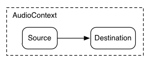
Illustrating this simple routing, here's a simple example playing a single
sound:
ECMAScript
            var context = new AudioContext();

            function playSound() {
                var source = context.createBufferSource();
                source.buffer = dogBarkingBuffer;
                source.connect(context.destination);
                source.noteOn(0);
            }
Here's a more complex example with three sources and a convolution reverb
send with a dynamics compressor at the final output stage:
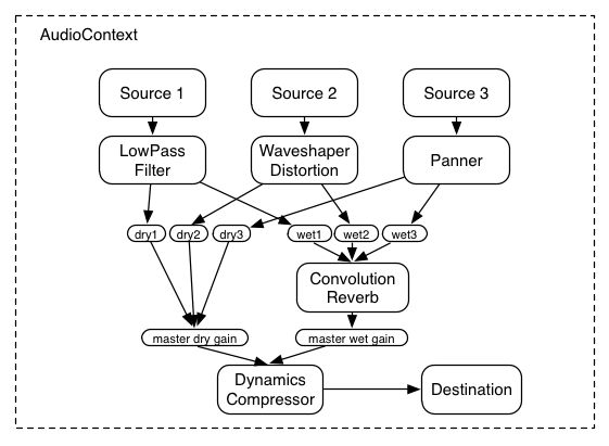
TODO: add Javascript example code here ...
1.3. API Overview
The interfaces defined are:
- An AudioContext
interface, which contains an audio signal graph representing connections
betweens AudioNodes.
- An AudioNode interface,
which represents audio sources, audio outputs, and intermediate processing
modules. AudioNodes can be dynamically connected together in a modular fashion.
AudioNodes
exist in the context of an AudioContext
- An AudioSourceNode
interface, an abstract AudioNode subclass representing a node which
generates audio.
- An AudioDestinationNode interface, an
AudioNode subclass representing the final destination for all rendered
audio.
- An AudioBuffer
interface, for working with memory-resident audio assets. These can
represent one-shot sounds, or longer audio clips.
- An AudioBufferSourceNode interface,
an AudioNode which generates audio from an AudioBuffer.
- A MediaElementAudioSourceNode
interface, an AudioNode which is the audio source from an
audio, video, or other media element.
- A JavaScriptAudioNode interface, an
AudioNode for generating or processing audio directly in JavaScript.
- An AudioProcessingEvent interface,
which is an event type used with
JavaScriptAudioNode objects.
- An AudioParam interface,
for controlling an individual aspect of an AudioNode's functioning, such as
volume.
- An AudioGainNode
interface, for explicit gain control. Because inputs to AudioNodes support
multiple connections (as a unity-gain summing junction), mixers can be easily built with AudioGainNodes.
- A BiquadFilterNode
interface, an AudioNode for common low-order filters such as:
- Low Pass
- High Pass
- Band Pass
- Low Shelf
- High Shelf
- Peaking
- Notch
- Allpass
- A DelayNode interface, an
AudioNode which applies a dynamically adjustable variable delay.
- An AudioPannerNode
interface, for spatializing / positioning audio in 3D space.
- An AudioListener
interface, which works with an
AudioPannerNode for
spatialization.
- A ConvolverNode
interface, an AudioNode for applying a real-time linear effect (such as the sound
of a concert hall).
- A RealtimeAnalyserNode interface,
for use with music visualizers, or other visualization applications.
- A AudioChannelSplitter interface,
for accessing the individual channels of an audio stream in the routing
graph.
- A AudioChannelMerger interface, for
combining channels from multiple audio streams into a single audio stream.
- A DynamicsProcessorNode interface, an
AudioNode for dynamic-shaping (compressor / expander) effects.
- A WaveShaperNode
interface, an AudioNode which applies a non-linear waveshaping effect for
distortion and other more subtle warming effects.
3. Terminology and Algorithms
This specification includes algorithms (steps) as part of the definition of
methods. Conforming implementations (referred to as "user agents" from here on)
MAY use other algorithms in the implementation of these methods, provided the
end result is the same.
4. The Audio API
4.1. The AudioContext Interface
This interface represents a set of AudioNode objects and their
connections. It allows for arbitrary routing of signals to the AudioDestinationNode
(what the user ultimately hears). Nodes are created from the context and are
then connected together. In most use
cases, only a single AudioContext is used per document. An AudioContext is
constructed as follows:
var context = new AudioContext();
IDL
interface AudioContext {
readonly attribute AudioDestinationNode destination;
readonly attribute float sampleRate;
readonly attribute float currentTime;
readonly attribute AudioListener listener;
readonly attribute unsigned long activeSourceCount;
AudioBuffer createBuffer(in unsigned long numberOfChannels, in unsigned long length, in float sampleRate)
raises(DOMException);
AudioBuffer createBuffer(in ArrayBuffer buffer, in boolean mixToMono)
raises(DOMException);
void decodeAudioData(in ArrayBuffer audioData,
in [Callback] AudioBufferCallback successCallback,
in [Optional, Callback] AudioBufferCallback errorCallback)
raises(DOMException);
AudioBufferSourceNode createBufferSource();
MediaElementAudioSourceNode createMediaElementSource(in HTMLMediaElement mediaElement)
raises(DOMException);
MediaStreamAudioSourceNode createMediaStreamSource(in MediaStream mediaStream)
raises(DOMException);
JavaScriptAudioNode createJavaScriptNode(in unsigned long bufferSize,
in [Optional] unsigned long numberOfInputChannels = 2,
in [Optional] unsigned long numberOfOutputChannels = 2)
raises(DOMException);
RealtimeAnalyserNode createAnalyser();
AudioGainNode createGainNode();
DelayNode createDelayNode(in [Optional] double maxDelayTime);
BiquadFilterNode createBiquadFilter();
AudioPannerNode createPanner();
ConvolverNode createConvolver();
AudioChannelSplitter createChannelSplitter(in [Optional] unsigned long numberOfOutputs = 6)
raises(DOMException);
AudioChannelMerger createChannelMerger(in [Optional] unsigned long numberOfInputs = 6);
raises(DOMException);
DynamicsCompressorNode createDynamicsCompressor();
Oscillator createOscillator();
WaveTable createWaveTable(in Float32Array real, in Float32Array imag)
raises(DOMException);
}
4.1.1. Attributes
destinationAn AudioDestinationNode
with a single input representing the final destination for all audio (to
be rendered to the audio hardware). All AudioNodes actively rendering
audio will directly or indirectly connect to destination.
sampleRateThe sample rate (in sample-frames per second) at which the
AudioContext handles audio. It is assumed that all AudioNodes in the
context run at this rate. In making this assumption, sample-rate
converters or "varispeed" processors are not supported in real-time
processing.
currentTimeThis is a time in seconds which starts at zero when the context is
created and increases in real-time. All scheduled times are relative to
it. This is not a "transport" time which can be started, paused, and
re-positioned. It is always moving forward. A GarageBand-like timeline
transport system can be very easily built on top of this (in JavaScript).
This time corresponds to an ever-increasing hardware timestamp.
listenerAn AudioListener
which is used for 3D spatialization.
activeSourceCountThe number of AudioBufferSourceNodes that are currently playing.
4.1.2. Methods and Parameters
- The
createBuffer method
Creates an AudioBuffer of the given size. The audio data in the
buffer will be zero-initialized (silent). An exception will be thrown if
the numberOfChannels or sampleRate are out-of-bounds.
The numberOfChannels parameter
determines how many channels the buffer will have. An implementation must support at least 32 channels.
The length parameter determines the size of
the buffer in sample-frames.
The sampleRate parameter describes
the sample-rate of the linear PCM audio data in the buffer in
sample-frames per second. An implementation must support sample-rates in at least the range 22050 to 96000.
- The
createBuffer from ArrayBuffer
method
Creates an AudioBuffer given the audio file data contained in the
ArrayBuffer. The ArrayBuffer can, for example, be loaded from an
XMLHttpRequest with the new responseType and
response attributes.
The buffer parameter contains the audio
file data (for example from a .wav file).
The mixToMono parameter determines if a
mixdown to mono will be performed. Normally, this would not be set.
- The
decodeAudioData method
Asynchronously decodes the audio file data contained in the
ArrayBuffer. The ArrayBuffer can, for example, be loaded from an
XMLHttpRequest with the new responseType and
response attributes. Audio file data can be in any of the
formats supported by the audio element.
The decodeAudioData() method is preferred over the createBuffer() from
ArrayBuffer method because it is asynchronous and does not block the main
JavaScript thread.
audioData is an ArrayBuffer containing
audio file data.
successCallback is a callback
function which will be invoked when the decoding is finished. The single
argument to this callback is an AudioBuffer representing the decoded PCM
audio data.
errorCallback is a callback function
which will be invoked if there is an error decoding the audio file
data.
- The
createBufferSource
method
Creates an AudioBufferSourceNode.
- The
createMediaElementSource
method
Creates a MediaElementAudioSourceNode given an HTMLMediaElement.
As a consequence of calling this method, audio playback from the HTMLMediaElement will be re-routed
into the processing graph of the AudioContext.
- The
createMediaStreamSource
method
Creates a MediaStreamAudioSourceNode given a MediaStream.
As a consequence of calling this method, audio playback from the MediaStream will be re-routed
into the processing graph of the AudioContext.
- The
createJavaScriptNode
method
Creates a JavaScriptAudioNode for
direct audio processing using JavaScript. An exception will be thrown if bufferSize or numberOfInputChannels or numberOfOutputChannels
are outside the valid range.
The bufferSize parameter determines the
buffer size in units of sample-frames. It must be one of the following
values: 256, 512, 1024, 2048, 4096, 8192, 16384. This value controls how
frequently the onaudioprocess event handler is called and
how many sample-frames need to be processed each call. Lower values for
bufferSize will result in a lower (better) latency. Higher values will be necessary to
avoid audio breakup and glitches. The
value chosen must carefully balance between latency and audio quality.
The numberOfInputChannels parameter (defaults to 2) and
determines the number of channels for this node's input. Values of up to 32 must be supported.
The numberOfOutputChannels parameter (defaults to 2) and
determines the number of channels for this node's output. Values of up to 32 must be supported.
It is invalid for both numberOfInputChannels and
numberOfOutputChannels to be zero.
- The
createAnalyser method
Creates a RealtimeAnalyserNode.
- The
createGainNode method
Creates an AudioGainNode.
- The
createDelayNode method
Creates a DelayNode
representing a variable delay line. The initial default delay time will
be 0 seconds.
The maxDelayTime parameter is
optional and specifies the maximum delay time allowed for the delay line.
If not specified, the maximum delay time defaults to 1 second.
- The
createBiquadFilter
method
Creates a BiquadFilterNode
representing a second order filter which can be configured as one of
several common filter types.
- The
createPanner method
Creates an AudioPannerNode.
- The
createConvolver method
Creates a ConvolverNode.
- The
createChannelSplitter
method
Creates an AudioChannelSplitter
representing a channel splitter. An exception will be thrown for invalid parameter values.
The numberOfOutputs parameter
determines the number of outputs. Values of up to 32 must be supported. If not specified, then 6 will be used.
- The
createChannelMerger
method
Creates an AudioChannelMerger
representing a channel merger. An exception will be thrown for invalid parameter values.
The numberOfInputs parameter
determines the number of inputs. Values of up to 32 must be supported. If not specified, then 6 will be used.
- The
createDynamicsCompressor method
Creates a DynamicsCompressorNode.
- The
createOscillator method
Creates an Oscillator.
- The
createWaveTable method
Creates a WaveTable representing a waveform containing arbitrary harmonic content.
The real and imag parameters must be of type Float32Array of equal
lengths greater than zero and less than or equal to 4096 or an exception will be thrown.
These parameters specify the Fourier coefficients of a
Fourier series representing the partials of a periodic waveform.
The created WaveTable will be used with an Oscillator
and will represent a normalized time-domain waveform having maximum absolute peak value of 1.
Another way of saying this is that the generated waveform of an Oscillator
will have maximum peak value at 0dBFS. Conveniently, this corresponds to the full-range of the signal values used by the Web Audio API.
Because the WaveTable will be normalized on creation, the real and imag parameters
represent relative values.
The real parameter represents an array of cosine terms (traditionally the A terms).
In audio terminology, the first element (index 0) is the DC-offset of the periodic waveform and is usually set to zero.
The second element (index 1) represents the fundamental frequency. The third element represents the first overtone, and so on.
The imag parameter represents an array of sine terms (traditionally the B terms).
The first element (index 0) should be set to zero (and will be ignored) since this term does not exist in the Fourier series.
The second element (index 1) represents the fundamental frequency. The third element represents the first overtone, and so on.
4.1.3. Lifetime
Once created, an AudioContext will not be garbage collected. It will live until the document goes away.
4.2. The AudioNode Interface
AudioNodes are the building blocks of an AudioContext. This interface
represents audio sources, the audio destination, and intermediate processing
modules. These modules can be connected together to form processing graphs for rendering audio to the
audio hardware. Each node can have inputs and/or outputs. An AudioSourceNode has no inputs
and a single output. An AudioDestinationNode has
one input and no outputs and represents the final destination to the audio
hardware. Most processing nodes such as filters will have one input and one
output.
For performance reasons, practical implementations will need to use block processing, with each AudioNode processing a
fixed number of sample-frames of size block-size. In order to get uniform behavior across implementations, we will define this
value explicitly. block-size is defined to be 128 sample-frames which corresponds to roughly 3ms at a sample-rate of 44.1KHz.
IDL
    interface AudioNode {

        void connect(in AudioNode destination, in [Optional] unsigned long output = 0, in [Optional] unsigned long input = 0)
            raises(DOMException);

        void connect(in AudioParam destination, in [Optional] unsigned long output = 0)
            raises(DOMException);

        void disconnect(in [Optional] unsigned long output = 0)
            raises(DOMException);

        readonly attribute AudioContext context;
        readonly attribute unsigned long numberOfInputs;
        readonly attribute unsigned long numberOfOutputs;

    }
4.2.1. Attributes
contextThe AudioContext which owns this AudioNode.
numberOfInputsThe number of inputs feeding into the AudioNode. This will be 0 for
an AudioSourceNode.
numberOfOutputsThe number of outputs coming out of the AudioNode. This will be 0
for an AudioDestinationNode.
4.2.2. Methods and Parameters
- The
connect to AudioNode method
Connects the AudioNode to another AudioNode.
The destination parameter is the
AudioNode to connect to.
The output parameter is an index
describing which output of the AudioNode from which to connect. An
out-of-bound value throws an exception.
The input parameter is an index describing
which input of the destination AudioNode to connect to. An out-of-bound
value throws an exception.
It is possible to connect an AudioNode output to more than one input
with multiple calls to connect(). Thus, "fanout" is supported.
It is possible to connect an AudioNode to another AudioNode which creates a cycle.
In other words, an AudioNode may connect to another AudioNode, which in turn connects back
to the first AudioNode. This is allowed only if there is at least one
DelayNode in the cycle or an exception will
be thrown.
- The
connect to AudioParam method
Connects the AudioNode to an AudioParam, controlling the parameter
value with an audio-rate signal.
It is possible to connect an AudioNode output to more than one AudioParam
with multiple calls to connect(). Thus, "fanout" is supported.
It is possible to connect more than one AudioNode output to a single AudioParam
with multiple calls to connect(). Thus, "fanin" is supported.
An AudioParam will take the rendered audio data from any AudioNode output connected to it and convert it to mono by down-mixing if it is not
already mono, then mix it together with other such outputs and finally will mix with the intrinsic
parameter value (the value the AudioParam would normally have without any audio connections), including any timeline changes
scheduled for the parameter.
The destination parameter is the
AudioParam to connect to.
The output parameter is an index
describing which output of the AudioNode from which to connect. An
out-of-bound value throws an exception.
- The
disconnect method
Disconnects an AudioNode's output.
The output parameter is an index
describing which output of the AudioNode to disconnect. An out-of-bound
value throws an exception.
4.2.3. Lifetime
An AudioNode will live as long as there are any references to it. There are several types of references:
- A normal JavaScript reference obeying normal garbage collection rules.
- A playing reference for an
AudioSourceNode. Please see details for each specific
AudioSourceNode sub-type. For example, both AudioBufferSourceNodes and OscillatorNodes maintain a playing
reference to themselves while they are in the SCHEDULED_STATE or PLAYING_STATE.
- A connection reference which occurs if another
AudioNode is connected to it.
- A tail-time reference which an
AudioNode maintains on itself as long as it has
any internal processing state which has not yet been emitted. For example, a ConvolverNode has
a tail which continues to play even after receiving silent input (think about clapping your hands in a large concert
hall and continuing to hear the sound reverberate throughout the hall). Some AudioNodes have this
property. Please see details for specific nodes.
Any AudioNodes which are connected in a cycle and are directly or indirectly connected to the
AudioDestinationNode of the AudioContext will stay alive as long as the AudioContext is alive.
When an AudioNode has no references it will be deleted. But before it is deleted, the implementation must disconnect the node
from any other AudioNodes which it is connected to. In this way it releases all connection references (3) it has to other nodes.
Regardless of any of the above references, an AudioNode will be deleted when its AudioContext is deleted.
4.3. The AudioSourceNode Interface
This is an abstract interface representing an audio source, an AudioNode which has no inputs and a
single output:
      numberOfInputs  : 0
      numberOfOutputs : 1
Subclasses of AudioSourceNode will implement specific types of audio
sources.
IDL
    interface AudioSourceNode : AudioNode {

    }
4.4. The AudioDestinationNode Interface
This is an AudioNode
representing the final audio destination and is what the user will ultimately
hear. It can be considered as an audio output device which is connected to
speakers. All rendered audio to be heard will be routed to this node, a
"terminal" node in the AudioContext's routing graph. There is only a single
AudioDestinationNode per AudioContext, provided through the
destination attribute of AudioContext.
      numberOfInputs  : 1
      numberOfOutputs : 0
IDL
    interface AudioDestinationNode : AudioNode {

        readonly attribute unsigned long maxNumberOfChannels;
        attribute unsigned long numberOfChannels;

    }
4.4.1. Attributes
maxNumberOfChannelsThe maximum number of channels that the numberOfChannels attribute can be set to.
An AudioDestinationNode representing the audio hardware end-point (the normal case) can potentially output more than
2 channels of audio if the audio hardware is multi-channel. maxNumberOfChannels is the maximum number of channels that
this hardware is capable of supporting. If this value is 0, then this indicates that maxNumberOfChannels may not be
changed. This will be the case for an AudioDestinationNode in an OfflineAudioContext.
numberOfChannelsThe number of channels of the destination's input. This value will default to 2, and may be set to any non-zero value less than or equal
to maxNumberOfChannels. An exception will be thrown if this value is not within the valid range. Giving a concrete example, if
the audio hardware supports 8-channel output, then we may set numberOfChannels to 8, and render 8-channels of output.
4.5. The AudioParam Interface
AudioParam controls an individual aspect of an AudioNode's functioning, such as
volume. The parameter can be set immediately to a particular value using the
"value" attribute. Additionally, value changes can be scheduled to happen at
very precise times (in the coordinate system of AudioContext.currentTime), for envelopes, volume fades, LFOs, filter sweeps, grain
windows, etc. In this way, arbitrary timeline-based automation curves can be
set on any AudioParam.
Some synthesis and processing AudioNodes have AudioParams as attributes whose values must
be taken into account on a per-audio-sample basis.
For other AudioParams, sample-accuracy is not important and the value changes can be sampled more coarsely.
Each individual AudioParam will specify that it is either an a-rate parameter
which means that its values must be taken into account on a per-audio-sample basis, or it is a k-rate parameter whose value
changes must be taken into account at least at a 3ms resolution, but can be more precise than this.
Because practical implementations will use block processing, and will process a fixed number of sample-frames at a time
(block-size sample-frames). For each block, the value of a k-rate
parameter will be sampled at the time of the very first sample-frame, and that value will be used for the entire block.
IDL
interface AudioParam {
attribute float value;
readonly attribute float minValue;
readonly attribute float maxValue;
readonly attribute float defaultValue;
void setValueAtTime(in float value, in float time);
void linearRampToValueAtTime(in float value, in float time);
void exponentialRampToValueAtTime(in float value, in float time);
void setTargetValueAtTime(in float targetValue, in float time, in float timeConstant);
void setValueCurveAtTime(in Float32Array values, in float time, in float duration);
void cancelScheduledValues(in float startTime);
}
4.5.1. Attributes
valueThe parameter's floating-point value. If a value is set outside the
allowable range described by minValue and
maxValue no exception is thrown, because these limits are just nominal and may be
exceeded.
minValueNominal minimum value. The value attribute may be set
lower than this value.
maxValueNominal maximum value. The value attribute may be set higher than this value.
defaultValueInitial value for the value attribute
4.5.2. Methods and Parameters
An AudioParam maintains a time-ordered event list which is initially empty. The times are in
the time coordinate system of AudioContext.currentTime. The events define a mapping from time to value. The following methods
can change the event list by adding a new event into the list of a type specific to the method. Each event
has a time associated with it, and the events will always be kept in time-order in the list. These
methods will be called automation methods:
- setValueAtTime() - SetValue
- linearRampToValueAtTime() - LinearRampToValue
- exponentialRampToValueAtTime() - ExponentialRampToValue
- setTargetValueAtTime() - SetTargetValue
- setValueCurveAtTime() - SetValueCurve
The following rules will apply when calling these methods:
- If one of these events is added at a time where there is already an event of the exact same type, then the new event will replace the old
one.
- If one of these events is added at a time where there is already one or more events of a different type, then it will be
placed in the list after them, but before events whose times are after the event.
- If setValueCurveAtTime() is called for time T and duration D and there are any events having a time greater than T, but less than
T + D, then an exception will be thrown. In other words, it's not ok to schedule a value curve during a time period containing other events.
- Similarly an exception will be thrown if any automation method is called at a time which is inside of the time interval
of a SetValueCurve event at time T and duration D.
- The
setValueAtTime method
Schedules a parameter value change at the given time.
The value parameter is the value the
parameter will change to at the given time.
The time parameter is the time in the same time coordinate system as AudioContext.currentTime.
If there are no more events after this SetValue event, then for t >= time, v(t) = value. In other words, the value will remain constant.
If the next event (having time T1) after this SetValue event is not of type LinearRampToValue or ExponentialRampToValue,
then, for t: time <= t < T1, v(t) = value.
In other words, the value will remain constant during this time interval, allowing the creation of "step" functions.
If the next event after this SetValue event is of type LinearRampToValue or ExponentialRampToValue then please
see details below.
- The
linearRampToValueAtTime
method
Schedules a linear continuous change in parameter value from the
previous scheduled parameter value to the given value.
The value parameter is the value the
parameter will linearly ramp to at the given time.
The time parameter is the time in the same time coordinate system as AudioContext.currentTime.
The value during the time interval T0 <= t < T1 (where T0 is the time of the previous event and T1 is the time parameter passed into this method)
will be calculated as:
v(t) = V0 + (V1 - V0) * ((t - T0) / (T1 - T0))
Where V0 is the value at the time T0 and V1 is the value parameter passed into this method.
If there are no more events after this LinearRampToValue event then for t >= T1, v(t) = V1
- The
exponentialRampToValueAtTime method
Schedules an exponential continuous change in parameter value from
the previous scheduled parameter value to the given value. Parameters
representing filter frequencies and playback rate are best changed
exponentially because of the way humans perceive sound.
The value parameter is the value the
parameter will exponentially ramp to at the given time. An exception will be thrown if this value is less than
or equal to 0, or if the value at the time of the previous event is less than or equal to 0.
The time parameter is the time in the same time coordinate system as AudioContext.currentTime.
The value during the time interval T0 <= t < T1 (where T0 is the time of the previous event and T1 is the time parameter passed into this method)
will be calculated as:
v(t) = V0 * (V1 / V0) ^ ((t - T0) / (T1 - T0))
Where V0 is the value at the time T0 and V1 is the value parameter passed into this method.
If there are no more events after this ExponentialRampToValue event then for t >= T1, v(t) = V1
- The
setTargetValueAtTime
method
Start exponentially approaching the target value at the given time
with a rate having the given time constant. Among other uses, this is
useful for implementing the "decay" and "release" portions of an ADSR
envelope. Please note that the parameter value does not immediately
change to the target value at the given time, but instead gradually
changes to the target value.
The targetValue parameter is the value
the parameter will start changing to at the given time.
The time parameter is the time in the same time coordinate system as AudioContext.currentTime.
The timeConstant parameter is the
time-constant value of first-order filter (exponential) approach to the
target value. The larger this value is, the slower the transition will
be.
More precisely, timeConstant is the time it takes a first-order linear continuous time-invariant system
to reach the value 1 - 1/e (around 63.2%) given a step input response (transition from 0 to 1 value).
During the time interval: T0 <= t < T1, where T0 is the time parameter and T1 represents the time of the event following this
event (or infinity if there are no following events):
v(t) = V1 + (V0 - V1) * exp(-(t - T0) / timeConstant)
Where V0 is the initial value (the .value attribute) at T0 (the time parameter) and V1 is equal to the targetValue
parameter.
- The
setValueCurveAtTime
method
Sets an array of arbitrary parameter values starting at the given
time for the given duration. The number of values will be scaled to fit
into the desired duration.
The values parameter is a Float32Array
representing a parameter value curve. These values will apply starting at
the given time and lasting for the given duration.
The time parameter is the time in the same time coordinate system as AudioContext.currentTime.
The duration parameter is the
amount of time in seconds (after the time parameter) where values will be calculated according to the values parameter..
During the time interval: time <= t < time + duration, values will be calculated:
v(t) = values[N * (t - time) / duration], where N is the length of the values array.
- The
cancelScheduledValues
method
Cancels all scheduled parameter changes with times greater than or
equal to startTime.
The startTime parameter is the starting
time at and after which any previously scheduled parameter changes will
be cancelled. It is a time in the same time coordinate system as AudioContext.currentTime.
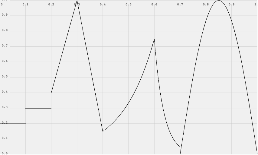
4.5.3. AudioParam Automation Example
ECMAScript
var t0 = 0;
var t1 = 0.1;
var t2 = 0.2;
var t3 = 0.3;
var t4 = 0.4;
var t5 = 0.6;
var t6 = 0.7;
var t7 = 1.0;

var curveLength = 44100;
var curve = new Float32Array(curveLength);
for (var i = 0; i < curveLength; ++i)
    curve[i] = Math.sin(Math.PI * i / curveLength);

param.setValueAtTime(0.2, t0);
param.setValueAtTime(0.3, t1);
param.setValueAtTime(0.4, t2);
param.linearRampToValueAtTime(1, t3);
param.linearRampToValueAtTime(0.15, t4);
param.exponentialRampToValueAtTime(0.75, t5);
param.exponentialRampToValueAtTime(0.05, t6);
param.setValueCurveAtTime(curve, t6, t7 - t6);
4.6. AudioGain
This interface is a particular type of AudioParam which
specifically controls the gain (volume) of some aspect of the audio processing.
The unit type is "linear gain". The nominal minValue is 0, but may be
set negative for phase inversion. The nominal maxValue is 1, but higher values are allowed (no
exception thrown).
IDL
  interface AudioGain : AudioParam {

  };
4.7. The AudioGainNode Interface
Changing the gain of an audio signal is a fundamental operation in audio
applications. The AudioGainNode is one of the building blocks for creating mixers.
This interface is an AudioNode with a single input and single
output:
    numberOfInputs  : 1
    numberOfOutputs : 1
which multiplies the input audio signal by the (possibly time-varying) gain attribute, copying the result to the output.
By default, it will take the input and pass it through to the output unchanged, which represents a constant gain change
of 1.
As with other AudioParams, the gain parameter represents a mapping from time
(in the coordinate system of AudioContext.currentTime) to floating-point value.
Every PCM audio sample in the input is multiplied by the gain parameter's value for the specific time
corresponding to that audio sample. This multiplied value represents the PCM audio sample for the output.
The number of channels of the output will always equal the number of channels of the input, with each channel
of the input being multiplied by the gain values and being copied into the corresponding channel
of the output.
The implementation must make
gain changes to the audio stream smoothly, without introducing noticeable
clicks or glitches. This process is called "de-zippering".
IDL
    interface AudioGainNode : AudioNode {

        AudioGain gain;

    }
4.7.1. Attributes
gainAn AudioGain object representing the amount of gain to apply. The
default value (gain.value) is 1 (no gain change). See AudioGain for more
information. This parameter is a-rate
4.8. The DelayNode Interface
A delay-line is a fundamental building block in audio applications. This
interface is an AudioNode with a single input and single output:
    numberOfInputs  : 1
    numberOfOutputs : 1
which delays the incoming audio signal by a certain amount. The default
amount is 0 seconds (no delay). When the delay time is changed, the
implementation must make the transition smoothly, without introducing
noticeable clicks or glitches to the audio stream.
IDL
    interface DelayNode : AudioNode {

        AudioParam delayTime;

    }
4.8.1. Attributes
delayTimeAn AudioParam object representing the amount of delay (in seconds)
to apply. The default value (delayTime.value) is 0 (no
delay). The minimum value is 0 and the maximum value is determined by the maxDelayTime
argument to the AudioContext method createDelayNode. This parameter is k-rate
4.9. The AudioBuffer Interface
This interface represents a memory-resident audio asset (for one-shot sounds
and other short audio clips). Its format is non-interleaved IEEE 32-bit linear PCM with a
nominal range of -1 -> +1. It can contain one or more channels. It is
analogous to a WebGL texture. Typically, it would be expected that the length
of the PCM data would be fairly short (usually somewhat less than a minute).
For longer sounds, such as music soundtracks, streaming should be used with the
audio element and MediaElementAudioSourceNode.
An AudioBuffer may be used by one or more AudioContexts.
IDL
interface AudioBuffer {
readonly attribute float sampleRate;
readonly attribute long length;
readonly attribute float duration;
readonly attribute int numberOfChannels;
Float32Array getChannelData(in unsigned long channel);
}
4.9.1. Attributes
sampleRateThe sample-rate for the PCM audio data in samples per second.
lengthLength of the PCM audio data in sample-frames.
durationDuration of the PCM audio data in seconds.
numberOfChannelsThe number of discrete audio channels.
4.9.2. Methods and Parameters
- The
getChannelData method
Returns the Float32Array representing the PCM audio data for the specific channel.
The channel parameter is an index
representing the particular channel to get data for. An index value of 0 represents
the first channel. This index value MUST be less than numberOfChannels
or an exception will be thrown.
4.10. The AudioBufferSourceNode Interface
This interface represents an audio source from an in-memory audio asset in
an AudioBuffer. It generally will be used for short audio assets
which require a high degree of scheduling flexibility (can playback in
rhythmically perfect ways). The playback state of an AudioBufferSourceNode goes
through distinct stages during its lifetime in this order: UNSCHEDULED_STATE,
SCHEDULED_STATE, PLAYING_STATE, FINISHED_STATE. The noteOn() method causes a transition from the
UNSCHEDULED_STATE to SCHEDULED_STATE. Depending on the time argument passed to
noteOn(), a transition is made from the SCHEDULED_STATE to PLAYING_STATE, at which
time sound is first generated. Following this, a transition from the PLAYING_STATE to
FINISHED_STATE happens when either the buffer's audio data has been completely
played (if the loop attribute is false), or when the noteOff()
method has been called and the specified time has been reached. Please see more
details in the noteOn() and noteOff() description. Once an
AudioBufferSourceNode has reached the FINISHED state it will no longer emit any
sound. Thus noteOn() and noteOff() may not be issued multiple times for a given
AudioBufferSourceNode.
    numberOfInputs  : 0
    numberOfOutputs : 1
IDL
interface AudioBufferSourceNode : AudioSourceNode {
const unsigned short UNSCHEDULED_STATE = 0;
const unsigned short SCHEDULED_STATE = 1;
const unsigned short PLAYING_STATE = 2;
const unsigned short FINISHED_STATE = 3;
readonly attribute unsigned short playbackState;
attribute AudioBuffer buffer;
attribute AudioParam playbackRate;
attribute boolean loop;
void noteOn(in double when);
void noteGrainOn(in double when, in double grainOffset, in double grainDuration);
void noteOff(in double when);
}
4.10.1. Attributes
playbackStateThe playback state, initialized to UNSCHEDULED_STATE.
bufferRepresents the audio asset to be played.
playbackRateThe speed at which to render the audio stream. The default
playbackRate.value is 1. This parameter is a-rate
loopIndicates if the audio data should play in a loop.
4.10.2. Methods and
Parameters
- The
noteOn method
Schedules a sound to playback at an exact time.
The when parameter describes at what time (in
seconds) the sound should start playing. It is in the same
time coordinate system as AudioContext.currentTime. If 0 is passed in for
this value or if the value is less than currentTime, then the
sound will start playing immediately. Either noteOn or noteGrainOn (but not both) may only be called one time
and must be called before noteOff is called or an exception will be thrown.
- The
noteGrainOn method
Schedules a portion of a sound to playback at an exact time.
The when parameter
describes at what time (in seconds) the sound should start playing.
It is in the same time coordinate system as AudioContext.currentTime.
If 0 is passed in for this value or if the value is less than
currentTime, then the sound will start playing immediately.
The grainOffset parameter describes
the offset in the buffer (in seconds) for the portion to be played.
The grainDuration parameter
describes the duration of the portion (in seconds) to be played.
Either noteOn or noteGrainOn (but not both) may only be called one time
and must be called before noteOff is called or an exception will be thrown.
- The
noteOff method
Schedules a sound to stop playback at an exact time.
The when parameter
describes at what time (in seconds) the sound should stop playing.
It is in the same time coordinate system as AudioContext.currentTime.
If 0 is passed in for this value or if the value is less than
currentTime, then the sound will stop playing immediately.
noteOff must only be called one time and only after a call to noteOn or noteOff,
or an exception will be thrown.
4.12. The JavaScriptAudioNode Interface
This interface is an AudioNode which can generate, process, or analyse audio
directly using JavaScript.
numberOfInputs : 1
numberOfOutputs : 1
The JavaScriptAudioNode is constructed with a bufferSize which
must be one of the following values: 256, 512, 1024, 2048, 4096, 8192, 16384.
This value controls how frequently the onaudioprocess event
handler is called and how many sample-frames need to be processed each call.
Lower numbers for bufferSize will result in a lower (better) latency. Higher numbers will be necessary to avoid
audio breakup and glitches. The value chosen
must carefully balance between latency and audio quality.
numberOfInputChannels and numberOfOutputChannels
determine the number of input and output channels. It is invalid for both
numberOfInputChannels and numberOfOutputChannels to
be zero.
var node = context.createJavaScriptNode(bufferSize, numberOfInputChannels, numberOfOutputChannels);
IDL
interface JavaScriptAudioNode : AudioNode {
attribute EventListener onaudioprocess;
readonly attribute long bufferSize;
}
4.12.1. Attributes
onaudioprocessAn event listener which is called periodically for audio processing.
An event of type AudioProcessingEvent
will be passed to the event handler.
bufferSizeThe size of the buffer (in sample-frames) which needs to be
processed each time onprocessaudio is called. Legal values
are (256, 512, 1024, 2048, 4096, 8192, 16384).
4.13. The AudioProcessingEvent Interface
This interface is a type of Event which is passed to the
onaudioprocess event handler used by JavaScriptAudioNode.
The event handler processes audio from the input (if any) by accessing the
audio data from the inputBuffer attribute. The audio data which is
the result of the processing (or the synthesized data if there are no inputs)
is then placed into the outputBuffer.
IDL
interface AudioProcessingEvent : Event {
JavaScriptAudioNode node;
readonly attribute float playbackTime;
readonly attribute AudioBuffer inputBuffer;
readonly attribute AudioBuffer outputBuffer;
}
4.13.1. Attributes
nodeThe JavaScriptAudioNode associated with this processing
event.
playbackTimeThe time when the audio will be played in the same time coordinate system as AudioContext.currentTime.
playbackTime allows for very tight synchronization between
processing directly in JavaScript with the other events in the context's
rendering graph.
inputBufferAn AudioBuffer containing the input audio data. It will have a number of channels equal to the numberOfInputChannels parameter
of the createJavaScriptNode() method. This AudioBuffer is only valid while in the scope of the onaudioprocess
function. Its values will be meaningless outside of this scope.
outputBufferAn AudioBuffer where the output audio data should be written. It will have a number of channels equal to the
numberOfOutputChannels parameter of the createJavaScriptNode() method.
Script code within the scope of the onaudioprocess function is expected to modify the
Float32Array arrays representing channel data in this AudioBuffer.
Any script modifications to this AudioBuffer outside of this scope will not produce any audible effects.
4.14. The AudioPannerNode Interface
This interface represents a processing node which positions / spatializes an incoming audio
stream in three-dimensional space. The spatialization is in relation to the AudioContext's AudioListener
(listener attribute).
numberOfInputs : 1
numberOfOutputs : 1
The audio stream from the input will be either mono or stereo, depending on the connection(s) to the input.
The output of this node is hard-coded to stereo (2 channels) and currently cannot be configured.
IDL
interface AudioPannerNode : AudioNode {
const unsigned short EQUALPOWER = 0;
const unsigned short HRTF = 1;
const unsigned short SOUNDFIELD = 2;
const unsigned short LINEAR_DISTANCE = 0;
const unsigned short INVERSE_DISTANCE = 1;
const unsigned short EXPONENTIAL_DISTANCE = 2;
attribute unsigned short panningModel;
void setPosition(in float x, in float y, in float z);
void setOrientation(in float x, in float y, in float z);
void setVelocity(in float x, in float y, in float z);
attribute unsigned short distanceModel;
attribute float refDistance;
attribute float maxDistance;
attribute float rolloffFactor;
attribute float coneInnerAngle;
attribute float coneOuterAngle;
attribute float coneOuterGain;
readonly attribute AudioGain coneGain;
readonly attribute AudioGain distanceGain;
};
4.14.1. Constants
EQUALPOWERA simple and efficient spatialization algorithm using equal-power
panning.
HRTFA higher quality spatialization algorithm using a convolution with
measured impulse responses from human subjects. This panning method
renders stereo output.
SOUNDFIELDAn algorithm which spatializes multi-channel audio using sound field
algorithms.
LINEAR_DISTANCEA linear distance model which calculates distanceGain according to:
1 - rolloffFactor * (distance - refDistance) / (maxDistance - refDistance)
INVERSE_DISTANCEAn inverse distance model which calculates distanceGain according to:
refDistance / (refDistance + rolloffFactor * (distance - refDistance))
EXPONENTIAL_DISTANCEAn exponential distance model which calculates distanceGain according to:
pow(distance / refDistance, -rolloffFactor)
4.14.2. Attributes
listenerRepresents the listener whose position and orientation is
used together with the panner's position and orientation to determine how
the audio will be spatialized.
panningModelDetermines which spatialization algorithm will be used to position
the audio in 3D space. See the constants for the available
choices. The default is HRTF.
distanceModelDetermines which algorithm will be used to reduce the volume of an
audio source as it moves away from the listener.
refDistanceA reference distance for reducing volume as source move further from
the listener.
maxDistanceThe maximum distance between source and listener, after which the
volume will not be reduced any further.
rolloffFactorDescribes how quickly the volume is reduced as source moves away
from listener.
coneInnerAngleA parameter for directional audio sources, this is an angle, inside
of which there will be no volume reduction.
coneOuterAngleA parameter for directional audio sources, this is an angle, outside
of which the volume will be reduced to a constant value of
coneOuterGain.
coneOuterGainA parameter for directional audio sources, this is the amount of
volume reduction outside of the coneOuterAngle.
4.14.3. Methods and Parameters
- The
setPosition method
Sets the position of the audio source relative to the
listener attribute. A 3D cartesian coordinate system is used.
The x, y, z parameters represent the coordinates
in 3D space.
- The
setOrientation method
Describes which direction the audio source is pointing in the 3D
cartesian coordinate space. Depending on how directional the sound is
(controlled by the cone attributes), a sound pointing away from
the listener can be very quiet or completely silent.
The x, y, z parameters represent a direction
vector in 3D space.
- The
setVelocity method
Sets the velocity vector of the audio source. This vector controls
both the direction of travel and the speed in 3D space. This velocity
relative to the listener's velocity is used to determine how much doppler
shift (pitch change) to apply.
The x, y, z parameters describe a direction
vector indicating direction of travel and intensity.
4.15. The AudioListener Interface
This interface represents the position and orientation of the person
listening to the audio scene. All AudioPannerNode objects
spatialize in relation to the AudioContext's listener. See this section for more details about
spatialization.
IDL
interface AudioListener {
attribute float dopplerFactor;
attribute float speedOfSound;
void setPosition(in float x, in float y, in float z);
void setOrientation(in float x, in float y, in float z, in float xUp, in float yUp, in float zUp);
void setVelocity(in float x, in float y, in float z);
};
4.15.1. Attributes
dopplerFactorA constant used to determine the amount of pitch shift to use when
rendering a doppler effect.
speedOfSoundThe speed of sound used for calculating doppler shift. The default
value is 343.3 meters / second.
4.15.2. Methods and Parameters
- The
setPosition method
Sets the position of the listener in a 3D cartesian coordinate
space. AudioPannerNode objects use this position relative to
individual audio sources for spatialization.
The x, y, z parameters represent
the coordinates in 3D space.
- The
setOrientation method
Describes which direction the listener is pointing in the 3D
cartesian coordinate space. Both a front vector and an up
vector are provided.
The x, y, z parameters represent
a front direction vector in 3D space.
The xUp, yUp, zUp parameters
represent an up direction vector in 3D space.
- The
setVelocity method
Sets the velocity vector of the listener. This vector controls both
the direction of travel and the speed in 3D space. This velocity relative
an audio source's velocity is used to determine how much doppler shift
(pitch change) to apply.
The x, y, z parameters describe a
direction vector indicating direction of travel and intensity.
4.16. The ConvolverNode Interface
This interface represents a processing node which applies a linear convolution effect given an impulse
response. Normative requirements for multi-channel convolution matrixing are described
here.
numberOfInputs : 1
numberOfOutputs : 1
IDL
interface ConvolverNode : AudioNode {
attribute AudioBuffer buffer;
attribute boolean normalize;
};
4.16.1. Attributes
bufferA mono, stereo, or 4-channel AudioBuffer containing the (possibly multi-channel) impulse response
used by the ConvolverNode. At the time when this attribute is set, the buffer and the state of the normalize
attribute will be used to configure the ConvolverNode with this impulse response having the given normalization.
normalizeControls whether the impulse response from the buffer will be scaled
by an equal-power normalization when the buffer atttribute
is set. Its default value is true in order to achieve a more
uniform output level from the convolver when loaded with diverse impulse
responses. If normalize is set to false, then
the convolution will be rendered with no pre-processing/scaling of the
impulse response. Changes to this value do not take effect until the next time
the buffer attribute is set.
If the normalize attribute is false when the buffer attribute is set then the
ConvolverNode will perform a linear convolution given the exact impulse response contained within the buffer.
Otherwise, if the normalize attribute is true when the buffer attribute is set then the
ConvolverNode will first perform a scaled RMS-power analysis of the audio data contained within buffer to calculate a
normalizationScale given this algorithm:
float calculateNormalizationScale(buffer)
{
const float GainCalibration = 0.00125;
const float GainCalibrationSampleRate = 44100;
const float MinPower = 0.000125;
// Normalize by RMS power.
size_t numberOfChannels = buffer->numberOfChannels();
size_t length = buffer->length();
float power = 0;
for (size_t i = 0; i < numberOfChannels; ++i) {
float* sourceP = buffer->channel(i)->data();
float channelPower = 0;
int n = length;
while (n--) {
float sample = *sourceP++;
channelPower += sample * sample;
}
power += channelPower;
}
power = sqrt(power / (numberOfChannels * length));
// Protect against accidental overload.
if (isinf(power) || isnan(power) || power < MinPower)
power = MinPower;
float scale = 1 / power;
// Calibrate to make perceived volume same as unprocessed.
scale *= GainCalibration;
// Scale depends on sample-rate.
if (buffer->sampleRate())
scale *= GainCalibrationSampleRate / buffer->sampleRate();
// True-stereo compensation.
if (buffer->numberOfChannels() == 4)
scale *= 0.5;
return scale;
}
During processing, the ConvolverNode will then take this calculated normalizationScale value and multiply it by the result of the linear convolution
resulting from processing the input with the impulse response (represented by the buffer) to produce the
final output. Or any mathematically equivalent operation may be used, such as pre-multiplying the
input by normalizationScale, or pre-multiplying a version of the impulse-response by normalizationScale.
4.17. The RealtimeAnalyserNode Interface
This interface represents a node which is able to provide real-time
frequency and time-domain analysis
information. The audio stream will be passed un-processed from input to output.
numberOfInputs : 1
numberOfOutputs : 1 Note that this output may be left unconnected.
IDL
interface RealtimeAnalyserNode : AudioNode {
void getFloatFrequencyData(in Float32Array array);
void getByteFrequencyData(in Uint8Array array);
void getByteTimeDomainData(in Uint8Array array);
attribute unsigned long fftSize;
readonly attribute unsigned long frequencyBinCount;
attribute float minDecibels;
attribute float maxDecibels;
attribute float smoothingTimeConstant;
};
4.17.1. Attributes
fftSizeThe size of the FFT used for frequency-domain analysis. This must be
a power of two.
frequencyBinCountHalf the FFT size.
minDecibelsThe minimum power value in the scaling range for the FFT analysis
data for conversion to unsigned byte values.
maxDecibelsThe maximum power value in the scaling range for the FFT analysis
data for conversion to unsigned byte values.
smoothingTimeConstantA value from 0 -> 1 where 0 represents no time averaging
with the last analysis frame.
4.17.2. Methods and Parameters
- The
getFloatFrequencyData
method
Copies the current frequency data into the passed floating-point
array. If the array has fewer elements than the frequencyBinCount, the
excess elements will be dropped.
The array parameter is where
frequency-domain analysis data will be copied.
- The
getByteFrequencyData
method
Copies the current frequency data into the passed unsigned byte
array. If the array has fewer elements than the frequencyBinCount, the
excess elements will be dropped.
The array parameter is where
frequency-domain analysis data will be copied.
- The
getByteTimeDomainData
method
Copies the current time-domain (waveform) data into the passed
unsigned byte array. If the array has fewer elements than the
frequencyBinCount, the excess elements will be dropped.
The array parameter is where time-domain
analysis data will be copied.
4.18. The AudioChannelSplitter Interface
The AudioChannelSplitter is for use in more advanced
applications and would often be used in conjunction with AudioChannelMerger.
numberOfInputs : 1
numberOfOutputs : Variable N (defaults to 6) // number of "active" (non-silent) outputs is determined by number of channels in the input
This interface represents an AudioNode for accessing the individual channels
of an audio stream in the routing graph. It has a single input, and a number of
"active" outputs which equals the number of channels in the input audio stream.
For example, if a stereo input is connected to an
AudioChannelSplitter then the number of active outputs will be two
(one from the left channel and one from the right). There are always a total
number of N outputs (determined by the numberOfOutputs parameter to the AudioContext method createChannelSplitter()),
The default number is 6 if this value is not provided. Any outputs
which are not "active" will output silence and would typically not be connected
to anything.
Example:
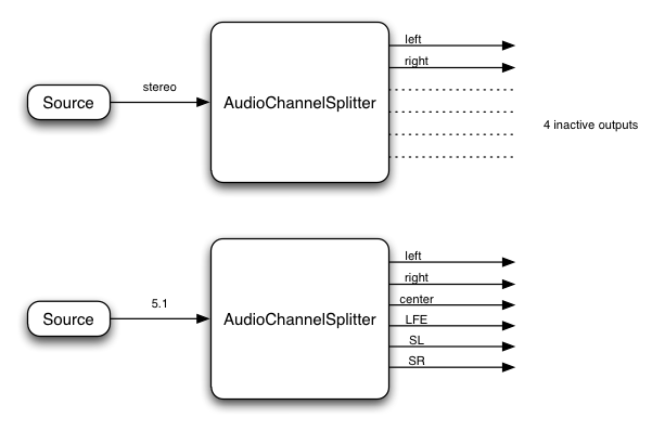
Please note that in this example, the splitter does not interpret the channel identities (such as left, right, etc.), but
simply splits out channels in the order that they are input.
One application for AudioChannelSplitter is for doing "matrix
mixing" where individual gain control of each channel is desired.
IDL
interface AudioChannelSplitter : AudioNode {
};
4.19. The AudioChannelMerger Interface
The AudioChannelMerger is for use in more advanced applications
and would often be used in conjunction with AudioChannelSplitter.
numberOfInputs : Variable N (default to 6) // number of connected inputs may be less than this
numberOfOutputs : 1
This interface represents an AudioNode for combining channels from multiple
audio streams into a single audio stream. It has a variable number of inputs (defaulting to 6), but not all of them
need be connected. There is a single output whose audio stream has a number of
channels equal to the sum of the numbers of channels of all the connected
inputs. For example, if an AudioChannelMerger has two connected
inputs (both stereo), then the output will be four channels, the first two from
the first input and the second two from the second input. In another example
with two connected inputs (both mono), the output will be two channels
(stereo), with the left channel coming from the first input and the right
channel coming from the second input.
Example:
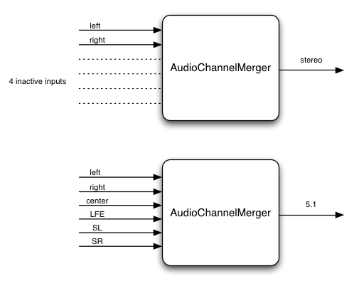
Please note that in this example, the merger does not interpret the channel identities (such as left, right, etc.), but
simply combines channels in the order that they are input.
Be aware that it is possible to connect an AudioChannelMerger
in such a way that it outputs an audio stream with a large number of channels
greater than the maximum supported by the audio hardware. In this case where such an output is connected
to the AudioContext .destination (the audio hardware), then the extra channels will be ignored.
Thus, the AudioChannelMerger should be used in situations where the number
of channels is well understood.
IDL
interface AudioChannelMerger : AudioNode {
};
4.20. The DynamicsCompressorNode Interface
DynamicsCompressorNode is an AudioNode processor implementing a dynamics
compression effect.
Dynamics compression is very commonly used in musical production and game
audio. It lowers the volume of the loudest parts of the signal and raises the
volume of the softest parts. Overall, a louder, richer, and fuller sound can be
achieved. It is especially important in games and musical applications where
large numbers of individual sounds are played simultaneous to control the
overall signal level and help avoid clipping (distorting) the audio output to
the speakers.
numberOfInputs : 1
numberOfOutputs : 1
IDL
interface DynamicsCompressorNode : AudioNode {
readonly attribute AudioParam threshold; // in Decibels
readonly attribute AudioParam knee; // in Decibels
readonly attribute AudioParam ratio; // unit-less
readonly attribute AudioParam reduction; // in Decibels
readonly attribute AudioParam attack; // in Seconds
readonly attribute AudioParam release; // in Seconds
}
4.20.1. Attributes
All parameters are k-rate
thresholdThe decibel value above which the compression will start taking
effect.
kneeA decibel value representing the range above the threshold where the
curve smoothly transitions to the "ratio" portion.
ratioThe amount of dB change in input for a 1 dB change in output.
reductionA read-only decibel value for metering purposes, representing the
current amount of gain reduction that the compressor is applying to the
signal.
attackThe amount of time to reduce the gain by 10dB.
releaseThe amount of time to increase the gain by 10dB.
4.21. The BiquadFilterNode Interface
BiquadFilterNode is an AudioNode processor implementing very common
low-order filters.
Low-order filters are the building blocks of basic tone controls (bass, mid,
treble), graphic equalizers, and more advanced filters. Multiple
BiquadFilterNode filters can be combined to form more complex filters. The
filter parameters such as "frequency" can be changed over time for filter
sweeps, etc. Each BiquadFilterNode can be configured as one of a number of
common filter types as shown in the IDL below. The default filter type
is LOWPASS
numberOfInputs : 1
numberOfOutputs : 1
IDL
interface BiquadFilterNode : AudioNode {
// Filter type.
const unsigned short LOWPASS = 0;
const unsigned short HIGHPASS = 1;
const unsigned short BANDPASS = 2;
const unsigned short LOWSHELF = 3;
const unsigned short HIGHSHELF = 4;
const unsigned short PEAKING = 5;
const unsigned short NOTCH = 6;
const unsigned short ALLPASS = 7;
attribute unsigned short type;
readonly attribute AudioParam frequency; // in Hertz
readonly attribute AudioParam Q; // Quality factor
readonly attribute AudioParam gain; // in Decibels
void getFrequencyResponse(in Float32Array frequencyHz,
in Float32Array magResponse,
in Float32Array phaseResponse);
}
The filter types are briefly described below. We note that all of these
filters are very commonly used in audio processing. In terms of implementation,
they have all been derived from standard analog filter prototypes. For more
technical details, we refer the reader to the excellent reference by
Robert Bristow-Johnson.
All parameters are k-rate
4.21.1 LOWPASS
A lowpass filter
allows frequencies below the cutoff frequency to pass through and attenuates
frequencies above the cutoff. LOWPASS implements a standard second-order
resonant lowpass filter with 12dB/octave rolloff.
- frequency
- The cutoff frequency above which the frequencies are attenuated
- Q
- Controls how peaked the response will be at the cutoff frequency. A
large value makes the response more peaked.
- gain
- Not used in this filter type
4.21.2 HIGHPASS
A highpass
filter is the opposite of a lowpass filter. Frequencies above the cutoff
frequency are passed through, but frequencies below the cutoff are attenuated.
HIGHPASS implements a standard second-order resonant highpass filter with
12dB/octave rolloff.
- frequency
- The cutoff frequency below which the frequencies are attenuated
- Q
- Controls how peaked the response will be at the cutoff frequency. A
large value makes the response more peaked.
- gain
- Not used in this filter type
4.21.3 BANDPASS
A bandpass
filter allows a range of frequencies to pass through and attenuates the
frequencies below and above this frequency range. BANDPASS implements a
second-order bandpass filter.
- frequency
- The center of the frequency band
- Q
- Controls the width of the band. The width becomes narrower as the Q
value increases.
- gain
- Not used in this filter type
4.21.4 LOWSHELF
The lowshelf filter allows all frequencies through, but adds a boost (or
attenuation) to the lower frequencies. LOWSHELF implements a second-order
lowshelf filter.
- frequency
- The upper limit of the frequences where the boost (or attenuation) is
applied.
- Q
- Not used in this filter type.
- gain
- The boost, in dB, to be applied. If the value is negative, the
frequencies are attenuated.
4.21.5 HIGHSHELF
The highshelf filter is the opposite of the lowshelf filter and allows all
frequencies through, but adds a boost to the higher frequencies. HIGHSHELF
implements a second-order highshelf filter
- frequency
- The lower limit of the frequences where the boost (or attenuation) is
applied.
- Q
- Not used in this filter type.
- gain
- The boost, in dB, to be applied. If the value is negative, the
frequencies are attenuated.
4.21.6 PEAKING
The peaking filter allows all frequencies through, but adds a boost (or
attenuation) to a range of frequencies.
- frequency
- The center frequency of where the boost is applied.
- Q
- Controls the width of the band of frequencies that are boosted. A
large value implies a narrow width.
- gain
- The boost, in dB, to be applied. If the value is negative, the
frequencies are attenuated.
4.21.7 NOTCH
The notch filter (also known as a band-stop or
band-rejection filter) is the opposite of a bandpass filter. It allows all
frequencies through, except for a set of frequencies.
- frequency
- The center frequency of where the notch is applied.
- Q
- Controls the width of the band of frequencies that are attenuated. A
large value implies a narrow width.
- gain
- Not used in this filter type.
4.21.8 ALLPASS
An allpass
filter allows all frequencies through, but changes the phase relationship
between the various frequencies. ALLPASS implements a second-order allpass
filter
- frequency
- The frequency where the center of the phase transition occurs. Viewed
another way, this is the frequency with maximal group delay.
- Q
- Controls how sharp the phase transition is at the center frequency. A
larger value implies a sharper transition and a larger group delay.
- gain
- Not used in this filter type.
4.21.9. Methods
- The
getFrequencyResponse
method
Given the current filter parameter settings, calculates the
frequency response for the specified frequencies.
The frequencyHz parameter specifies an
array of frequencies at which the response values will be calculated.
The magResponse parameter specifies an
output array receiving the linear magnitude response values.
The phaseResponse parameter
specifies an output array receiving the phase response values in
radians.
4.22. The WaveShaperNode Interface
WaveShaperNode is an AudioNode processor implementing non-linear distortion
effects.
Non-linear waveshaping distortion is commonly used for both subtle
non-linear warming, or more obvious distortion effects. Arbitrary non-linear
shaping curves may be specified.
numberOfInputs : 1
numberOfOutputs : 1
IDL
interface WaveShaperNode : AudioNode {
attribute Float32Array curve;
}
4.22.1. Attributes
curveThe shaping curve used for the waveshaping effect. The input signal
is nominally within the range -1 -> +1. Each input sample within this
range will index into the shaping curve with a signal level of zero
corresponding to the center value of the curve array. Any sample value
less than -1 will correspond to the first value in the curve array. Any
sample value less greater than +1 will correspond to the last value in
the curve array.
4.23. The Oscillator Interface
Oscillator represents an audio source generating a periodic waveform. It can be set to
a few commonly used waveforms. Additionally, it can be set to an arbitrary periodic
waveform through the use of a WaveTable object.
Oscillators are common foundational building blocks in audio synthesis. An Oscillator will start emitting sound at the time
specified by the noteOn() method.
Mathematically speaking, a continuous-time periodic waveform can have very high (or infinitely high) frequency information when considered
in the frequency domain. When this waveform is sampled as a discrete-time digital audio signal at a particular sample-rate,
then care must be taken to discard (filter out) the high-frequency information higher than the Nyquist frequency (half the sample-rate)
before converting the waveform to a digital form. If this is not done, then aliasing of higher frequencies (than the Nyquist frequency) will fold
back as mirror images into frequencies lower than the Nyquist frequency. In many cases this will cause audibly objectionable artifacts.
This is a basic and well understood principle of audio DSP.
There are several practical approaches that an implementation may take to avoid this aliasing.
But regardless of approach, the idealized discrete-time digital audio signal is well defined mathematically.
The trade-off for the implementation is a matter of implementation cost (in terms of CPU usage) versus fidelity to
achieving this ideal.
It is expected that an implementation will take some care in achieving this ideal, but it is reasonable to consider lower-quality,
less-costly approaches on lower-end hardware.
    numberOfInputs  : 0
    numberOfOutputs : 1
IDL
    interface Oscillator : AudioSourceNode {

        // Type constants.
        const unsigned short SINE = 0;
        const unsigned short SQUARE = 1;
        const unsigned short SAWTOOTH = 2;
        const unsigned short TRIANGLE = 3;
        const unsigned short CUSTOM = 4;

        attribute unsigned short type;

        const unsigned short UNSCHEDULED_STATE = 0;
        const unsigned short SCHEDULED_STATE = 1;
        const unsigned short PLAYING_STATE = 2;
        const unsigned short FINISHED_STATE = 3;

        readonly attribute unsigned short playbackState;

        readonly attribute AudioParam frequency; // in Hertz
        readonly attribute AudioParam detune; // in Cents

        void noteOn(in double when);
        void noteOff(in double when);
        void setWaveTable(in WaveTable waveTable);

    }
4.23.1. Attributes
typeThe shape of the periodic waveform. It may directly be set to any of the type constant values except for CUSTOM.
The setWaveTable() method can be used to set a custom waveform, which results in this attribute
being set to CUSTOM.
playbackStatedefined as in AudioBufferSourceNode.
frequencyThe frequency (in Hertz) of the periodic waveform. This parameter is a-rate
detuneA detuning value (in Cents) which will offset the frequency by the given amount.
This parameter is a-rate
5. Integration with the audio and
video elements
A MediaElementAudioSourceNode
can be created from an HTMLMediaElement using an AudioContext method.
ECMAScript
var mediaElement = document.getElementById('mediaElementID');
var sourceNode = context.createMediaElementSource(mediaElement);
sourceNode.connect(filterNode);
6. Mixer Gain Structure
Background
One of the most important considerations when dealing with audio processing
graphs is how to adjust the gain (volume) at various points. For example, in a
standard mixing board model, each input bus has pre-gain, post-gain, and
send-gains. Submix and master out busses also have gain control. The gain
control described here can be used to implement standard mixing boards as well
as other architectures.
Summing Inputs
The inputs to AudioNodes have
the ability to accept connections from multiple outputs. The input then acts as
a unity gain summing junction with each output signal being added with the
others:
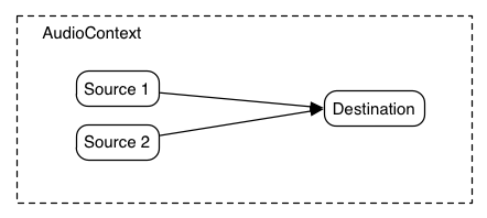
In cases where the channel layouts of the outputs do not match, an up-mix will occur to the highest number of channels.
Gain Control
But many times, it's important to be able to control the gain for each of
the output signals. The AudioGainNode gives this
control:
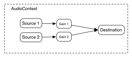
Using these two concepts of unity gain summing junctions and AudioGainNodes,
it's possible to construct simple or complex mixing scenarios.
Example: Mixer with Send Busses
In a routing scenario involving multiple sends and submixes, explicit
control is needed over the volume or "gain" of each connection to a mixer. Such
routing topologies are very common and exist in even the simplest of electronic
gear sitting around in a basic recording studio.
Here's an example with two send mixers and a main mixer. Although possible,
for simplicity's sake, pre-gain control and insert effects are not illustrated:
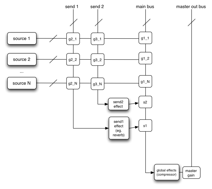
This diagram is using a shorthand notation where "send 1", "send 2", and
"main bus" are actually inputs to AudioNodes, but here are represented as
summing busses, where the intersections g2_1, g3_1, etc. represent the "gain"
or volume for the given source on the given mixer. In order to expose this
gain, an AudioGainNode is used:
Here's how the above diagram could be constructed in JavaScript:
ECMAScript
var context = 0;
var compressor = 0;
var reverb = 0;
var delay = 0;
var s1 = 0;
var s2 = 0;
var source1 = 0;
var source2 = 0;
var g1_1 = 0;
var g2_1 = 0;
var g3_1 = 0;
var g1_2 = 0;
var g2_2 = 0;
var g3_2 = 0;
function setupRoutingGraph() {
context = new AudioContext();
compressor = context.createDynamicsCompressor();
reverb = context.createConvolver();
delay = context.createDelayNode();
compressor.connect(context.destination);
s1 = context.createGainNode();
reverb.connect(s1);
s1.connect(compressor);
s2 = context.createGainNode();
delay.connect(s2);
s2.connect(compressor);
source1 = context.createBufferSource();
source2 = context.createBufferSource();
source1.buffer = manTalkingBuffer;
source2.buffer = footstepsBuffer;
g1_1 = context.createGainNode();
g2_1 = context.createGainNode();
g3_1 = context.createGainNode();
source1.connect(g1_1);
source1.connect(g2_1);
source1.connect(g3_1);
g1_1.connect(compressor);
g2_1.connect(reverb);
g3_1.connect(delay);
g1_2 = context.createGainNode();
g2_2 = context.createGainNode();
g3_2 = context.createGainNode();
source2.connect(g1_2);
source2.connect(g2_2);
source2.connect(g3_2);
g1_2.connect(compressor);
g2_2.connect(reverb);
g3_2.connect(delay);
g2_1.gain.value = 0.2;
}
7. Dynamic Lifetime
Background
This section is informative. Please see AudioContext lifetime
and AudioNode lifetime for normative requirements
In addition to allowing the creation of static routing configurations, it
should also be possible to do custom effect routing on dynamically allocated
voices which have a limited lifetime. For the purposes of this discussion,
let's call these short-lived voices "notes". Many audio applications
incorporate the ideas of notes, examples being drum machines, sequencers, and
3D games with many one-shot sounds being triggered according to game play.
In a traditional software synthesizer, notes are dynamically allocated and
released from a pool of available resources. The note is allocated when a MIDI
note-on message is received. It is released when the note has finished playing
either due to it having reached the end of its sample-data (if non-looping), it
having reached a sustain phase of its envelope which is zero, or due to a MIDI
note-off message putting it into the release phase of its envelope. In the MIDI
note-off case, the note is not released immediately, but only when the release
envelope phase has finished. At any given time, there can be a large number of
notes playing but the set of notes is constantly changing as new notes are
added into the routing graph, and old ones are released.
The audio system automatically deals with tearing-down the part of the
routing graph for individual "note" events. A "note" is represented by an
AudioBufferSourceNode, which can be directly connected to other
processing nodes. When the note has finished playing, the context will
automatically release the reference to the AudioBufferSourceNode,
which in turn will release references to any nodes it is connected to, and so
on. The nodes will automatically get disconnected from the graph and will be
deleted when they have no more references. Nodes in the graph which are
long-lived and shared between dynamic voices can be managed explicitly.
Although it sounds complicated, this all happens automatically with no extra
JavaScript handling required.
Example
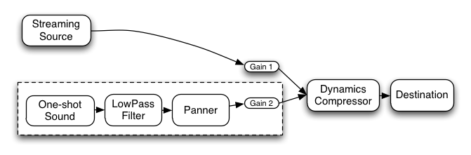
The low-pass filter, panner, and second gain nodes are directly connected
from the one-shot sound. So when it has finished playing the context will
automatically release them (everything within the dotted line). If there are no
longer any JavaScript references to the one-shot sound and connected nodes,
then they will be immediately removed from the graph and deleted. The streaming
source, has a global reference and will remain connected until it is explicitly
disconnected. Here's how it might look in JavaScript:
ECMAScript
var context = 0;
var compressor = 0;
var gainNode1 = 0;
var streamingAudioSource = 0;
function setupAudioContext() {
context = new AudioContext();
compressor = context.createDynamicsCompressor();
gainNode1 = context.createGainNode();
// Create a streaming audio source.
var audioElement = document.getElementById('audioTagID');
streamingAudioSource = context.createMediaElementSource(audioElement);
streamingAudioSource.connect(gainNode1);
gainNode1.connect(compressor);
compressor.connect(context.destination);
}
function playSound() {
var oneShotSound = context.createBufferSource();
oneShotSound.buffer = dogBarkingBuffer;
var lowpass = context.createBiquadFilter();
var panner = context.createPanner();
var gainNode2 = context.createGainNode();
oneShotSound.connect(lowpass);
lowpass.connect(panner);
panner.connect(gainNode2);
gainNode2.connect(compressor);
oneShotSound.noteOn(context.currentTime + 0.75);
}
8. Channel Layouts
It's important to define the channel ordering (and define some
abbreviations) for different layouts.
The channel layouts are clear:
  Mono
    0: M: mono

  Stereo
    0: L: left
    1: R: right
A more advanced implementation can handle channel layouts for quad and 5.1:
  Quad
    0: L:  left
    1: R:  right
    2: SL: surround left
    3: SR: surround right

  5.1
    0: L:   left
    1: R:   right
    2: C:   center
    3: LFE: subwoofer
    4: SL:  surround left
    5: SR:  surround right
Other layouts can also be considered.
9. Channel up-mixing and down-mixing
For now, only considers cases for mono, stereo, quad, 5.1. Later other channel
layouts can be defined.
Up Mixing
Consider what happens when converting an audio stream with a lower number of
channels to one with a higher number of channels. This can be necessary when mixing several outputs together where the
channel layouts differ. It can also be necessary if the rendered audio stream
is played back on a system with more channels.
Mono up-mix:

    1 -> 2 : up-mix from mono to stereo
        output.L = input;
        output.R = input;

    1 -> 4 : up-mix from mono to quad
        output.L = input;
        output.R = input;
        output.SL = 0;
        output.SR = 0;

    1 -> 5.1 : up-mix from mono to 5.1
        output.L = 0;
        output.R = 0;
        output.C = input; // put in center channel
        output.LFE = 0;
        output.SL = 0;
        output.SR = 0;

Stereo up-mix:

    2 -> 4 : up-mix from stereo to quad
        output.L = input.L;
        output.R = input.R;
        output.SL = 0;
        output.SR = 0;

    2 -> 5.1 : up-mix from stereo to 5.1
        output.L = input.L;
        output.R = input.R;
        output.C = 0;
        output.LFE = 0;
        output.SL = 0;
        output.SR = 0;

Quad up-mix:

    4 -> 5.1 : up-mix from stereo to 5.1
        output.L = input.L;
        output.R = input.R;
        output.C = 0;
        output.LFE = 0;
        output.SL = input.SL;
        output.SR = input.SR;
Down Mixing
A down-mix will be necessary, for example, if processing 5.1 source
material, but playing back stereo.
Mono down-mix:

    2 -> 1 : stereo to mono
        output = 0.5 * (input.L + input.R);

    4 -> 1 : quad to mono
        output = 0.25 * (input.L + input.R + input.SL + input.SR);

    5.1 -> 1 : 5.1 to mono
        ???


Stereo down-mix:

    4 -> 2 : quad to stereo
        output.L = 0.5 * (input.L + input.SL);
        output.R = 0.5 * (input.R + input.SR);

    5.1 -> 2 : 5.1 to stereo
        ???
10. Event Scheduling
Need more detail here, but for now:
- Audio events such as start/stop play and volume fades can be scheduled to
happen in a rhythmically perfect way (sample-accurate scheduling)
- Allows sequencing applications such as drum-machines, digital-dj mixers.
Ultimately, it may be useful for DAW applications.
- Allows rhythmically accurate segueways from one section of music to
another (as is possible with the FMOD engine).
- Allows scheduling of sound "grains" for granular synthesis effects.
11. Spatialization / Panning
Background
A common feature requirement for modern 3D games is the ability to
dynamically spatialize and move multiple audio sources in 3D space. Game audio
engines such as OpenAL, FMOD, Creative's EAX, Microsoft's XACT Audio, etc. have
this ability.
Using an AudioPannerNode, an audio stream can be spatialized or
positioned in space relative to an AudioListener. An AudioContext will contain a
single AudioListener. Both panners and listeners have a position
in 3D space using a right-handed cartesian coordinate system. AudioPannerNode
objects (representing the source stream) have an orientation
vector representing in which direction the sound is projecting. Additionally,
they have a sound cone representing how directional the sound is.
For example, the sound could be omnidirectional, in which case it would be
heard anywhere regardless of its orientation, or it can be more directional and
heard only if it is facing the listener. AudioListener objects
(representing a person's ears) have an orientation and
up vector representing in which direction the person is facing.
Because both the source stream and the listener can be moving, they both have a
velocity vector representing both the speed and direction of
movement. Taken together, these two velocities can be used to generate a
doppler shift effect which changes the pitch.
During rendering, the AudioPannerNode calculates an azimuth
and elevation. These values are used internally by the implementation in
order to render the spatialization effect. See the Panning Algorithm section
for details of how these values are used.
The following algorithm must be used to calculate the azimuth
and elevation:
// Calculate the source-listener vector.
vec3 sourceListener = source.position - listener.position;

if (sourceListener.isZero()) {
    // Handle degenerate case if source and listener are at the same point.
    azimuth = 0;
    elevation = 0;
    return;
}

sourceListener.normalize();

// Align axes.
vec3 listenerFront = listener.orientation;
vec3 listenerUp = listener.up;
vec3 listenerRight = listenerFront.cross(listenerUp);
listenerRight.normalize();

vec3 listenerFrontNorm = listenerFront;
listenerFrontNorm.normalize();

vec3 up = listenerRight.cross(listenerFrontNorm);

float upProjection = sourceListener.dot(up);

vec3 projectedSource = sourceListener - upProjection * up;
projectedSource.normalize();

azimuth = 180 * acos(projectedSource.dot(listenerRight)) / PI;

// Source in front or behind the listener.
double frontBack = projectedSource.dot(listenerFrontNorm);
if (frontBack < 0)
    azimuth = 360 - azimuth;

// Make azimuth relative to "front" and not "right" listener vector.
if ((azimuth >= 0) && (azimuth <= 270))
    azimuth = 90 - azimuth;
else
    azimuth = 450 - azimuth;

elevation = 90 - 180 * acos(sourceListener.dot(up)) / PI;

if (elevation > 90)
    elevation = 180 - elevation;
else if (elevation < -90)
    elevation = -180 - elevation;
Panning Algorithm
mono->stereo and stereo->stereo panning must be supported.
mono->stereo processing is used when all connections to the input are mono.
Otherwise stereo->stereo processing is used.
The following algorithms must be implemented:
- Equal-power (Vector-based) panning
This is a simple and relatively inexpensive algorithm which provides
basic, but reasonable results. It is commonly used when panning musical sources.
The elevation value is ignored in this panning algorithm.
The following steps are used for processing:
-
The azimuth value is first contained to be within the range -90 <= azimuth <= +90 according to:
    // Clamp azimuth to allowed range of -180 -> +180.
    azimuth = max(-180, azimuth);
    azimuth = min(180, azimuth);

    // Now wrap to range -90 -> +90.
    if (azimuth < -90)
        azimuth = -180 - azimuth;
    else if (azimuth > 90)
        azimuth = 180 - azimuth;
-
A 0 -> 1 normalized value x is calculated from azimuth for mono->stereo as:
x = (azimuth + 90) / 180
Or for stereo->stereo as:
    if (azimuth <= 0) { // from -90 -> 0
        // inputL -> outputL and "equal-power pan" inputR as in mono case
        // by transforming the "azimuth" value from -90 -> 0 degrees into the range -90 -> +90.
        x = (azimuth + 90) / 90;
    } else { // from 0 -> +90
        // inputR -> outputR and "equal-power pan" inputL as in mono case
        // by transforming the "azimuth" value from 0 -> +90 degrees into the range -90 -> +90.
        x = azimuth / 90;
    }
-
Left and right gain values are then calculated:
    gainL = cos(0.5 * PI * x);
    gainR = sin(0.5 * PI * x);
-
For mono->stereo, the output is calculated as:
    outputL = input * gainL
    outputR = input * gainR
Else for stereo->stereo, the output is calculated as:
    if (azimuth <= 0) { // from -90 -> 0
        outputL = inputL + inputR * gainL;
        outputR = inputR * gainR;
    } else { // from 0 -> +90
        outputL = inputL * gainL;
        outputR = inputR + inputL * gainR;
    }
- HRTF
panning (stereo only)
This requires a set of HRTF impulse responses recorded at a variety of
azimuths and elevations. There are a small number of open/free impulse
responses available. The implementation requires a highly optimized
convolution function. It is somewhat more costly than "equal-power", but
provides a more spatialized sound.
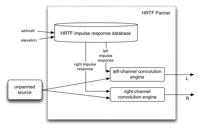
Distance Effects
Sounds which are closer are louder, while sounds further away are quieter.
Exactly how a sound's volume changes according to distance from the listener
depends on the distanceModel attribute.
During audio rendering, a distance value will be calculated based on the panner and listener positions according to:
v = panner.position - listener.position
distance = sqrt(dot(v, v))
distance will then be used to calculate distanceGain which depends
on the distanceModel attribute. See the Constants section for details of
how this is calculated for each distance model.
As part of its processing, the AudioPannerNode scales/multiplies the input audio signal by distanceGain
to make distant sounds quieter and nearer ones louder.
Sound Cones
The listener and each sound source have an orientation vector describing
which way they are facing. Each sound source's sound projection characteristics
are described by an inner and outer "cone" describing the sound intensity as a
function of the source/listener angle from the source's orientation vector.
Thus, a sound source pointing directly at the listener will be louder than if
it is pointed off-axis. Sound sources can also be omni-directional.
Doppler Shift
- Introduces a pitch shift which can realistically simulate moving
sources.
- Depends on: source / listener velocity vectors, speed of sound, doppler
factor.
12. Linear Effects using Convolution
Background
Convolution is a
mathematical process which can be applied to an audio signal to achieve many
interesting high-quality linear effects. Very often, the effect is used to
simulate an acoustic space such as a concert hall, cathedral, or outdoor
amphitheater. It can also be used for complex filter effects, like a muffled
sound coming from inside a closet, sound underwater, sound coming through a
telephone, or playing through a vintage speaker cabinet. This technique is very
commonly used in major motion picture and music production and is considered to
be extremely versatile and of high quality.
Each unique effect is defined by an impulse response. An
impulse response can be represented as an audio file and can be recorded from a real acoustic
space such as a cave, or can be synthetically generated through a great variety
of techniques.
Motivation for use as a Standard
A key feature of many game audio engines (OpenAL, FMOD, Creative's EAX,
Microsoft's XACT Audio, etc.) is a reverberation effect for simulating the
sound of being in an acoustic space. But the code used to generate the effect
has generally been custom and algorithmic (generally using a hand-tweaked set
of delay lines and allpass filters which feedback into each other). In nearly
all cases, not only is the implementation custom, but the code is proprietary
and closed-source, each company adding its own "black magic" to achieve its
unique quality. Each implementation being custom with a different set of
parameters makes it impossible to achieve a uniform desired effect. And the
code being proprietary makes it impossible to adopt a single one of the
implementations as a standard. Additionally, algorithmic reverberation effects
are limited to a relatively narrow range of different effects, regardless of
how the parameters are tweaked.
A convolution effect solves these problems by using a very precisely defined
mathematical algorithm as the basis of its processing. An impulse response
represents an exact sound effect to be applied to an audio stream and is easily
represented by an audio file which can be referenced by URL. The range of
possible effects is enormous.
Implementation Guide
Linear convolution can be implemented efficiently.
Here are some notes
describing how it can be practically implemented.
Reverb Effect (with matrixing)
This section is normative.
In the general case the source
has N input channels, the impulse response has K channels, and the playback
system has M output channels. Thus it's a matter of how to matrix these
channels to achieve the final result.
The subset of N, M, K below must be implemented (note that the first image in the diagram is just illustrating
the general case and is not normative, while the following images are normative).
Without loss of generality, developers desiring more complex and arbitrary matrixing can use multiple ConvolverNode
objects in conjunction with an AudioChannelMerger.
Single channel convolution operates on a mono audio input, using a mono
impulse response, and generating a mono output. But to achieve a more spacious sound, 2 channel audio
inputs and 1, 2, or 4 channel impulse responses will be considered. The following diagram, illustrates the
common cases for stereo playback where N and M are 1 or 2 and K is 1, 2, or 4.
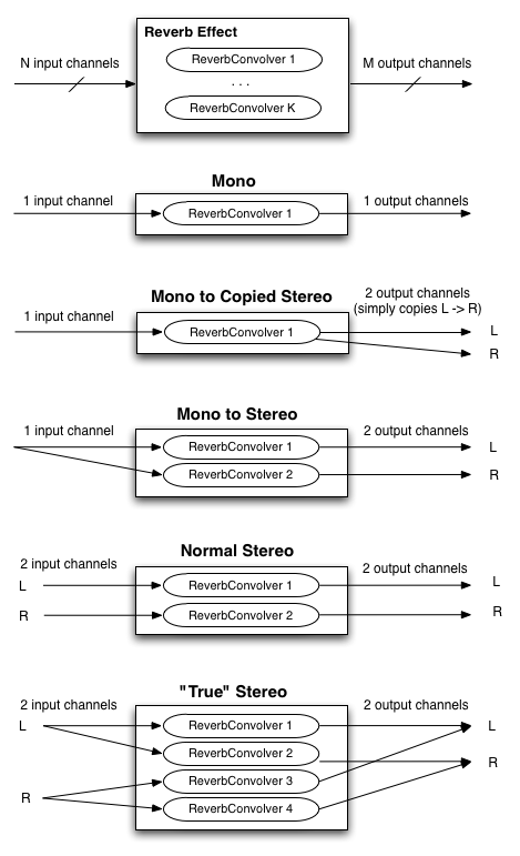
Recording Impulse Responses
This section is informative.
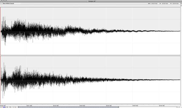
The most modern and
accurate way to record the impulse response of a real acoustic space is to use
a long exponential sine sweep. The test-tone can be as long as 20 or 30
seconds, or longer.
Several recordings of the test tone played through a speaker can be made with
microphones placed and oriented at various positions in the room. It's
important to document speaker placement/orientation, the types of microphones,
their settings, placement, and orientations for each recording taken.
Post-processing is required for each of these recordings by performing an
inverse-convolution with the test tone, yielding the impulse response of the
room with the corresponding microphone placement. These impulse responses are
then ready to be loaded into the convolution reverb engine to re-create the
sound of being in the room.
Two command-line tools have been written:
generate_testtones generates an exponential sine-sweep test-tone
and its inverse. Another tool convolve was written for
post-processing. With these tools, anybody with recording equipment can record
their own impulse responses. To test the tools in practice, several recordings
were made in a warehouse space with interesting acoustics. These were later
post-processed with the command-line tools.
% generate_testtones -h
Usage: generate_testtone
	[-o /Path/To/File/To/Create] Two files will be created: .tone and .inverse
	[-rate <sample rate>] sample rate of the generated test tones
	[-duration <duration>] The duration, in seconds, of the generated files
	[-min_freq <min_freq>] The minimum frequency, in hertz, for the sine sweep

% convolve -h
Usage: convolve input_file impulse_response_file output_file
Recording Setup
Audio Interface: Metric Halo Mobile I/O 2882
Microphones: AKG 414s, Speaker: Mackie HR824
The Warehouse Space
13. JavaScript Synthesis and Processing
This section is informative.
The Mozilla project has conducted Experiments to synthesize
and process audio directly in JavaScript. This approach is interesting for a
certain class of audio processing and they have produced a number of impressive
demos. This specification includes a means of synthesizing and processing
directly using JavaScript by using a special subtype of AudioNode called JavaScriptAudioNode.
Here are some interesting examples where direct JavaScript processing can be
useful:
Custom DSP Effects
Unusual and interesting custom audio processing can be done directly in JS.
It's also a good test-bed for prototyping new algorithms. This is an extremely
rich area.
Educational Applications
JS processing is ideal for illustrating concepts in computer music synthesis
and processing, such as showing the de-composition of a square wave into its
harmonic components, FM synthesis techniques, etc.
JavaScript has a variety of performance issues so it is not
suitable for all types of audio processing. The approach proposed in this
document includes the ability to perform computationally intensive aspects of
the audio processing (too expensive for JavaScript to compute in real-time)
such as multi-source 3D spatialization and convolution in optimized C++ code.
Both direct JavaScript processing and C++ optimized code can be combined due to
the APIs modular approach.
14. Realtime Analysis
15.1. Latency: What it is and Why it's Important
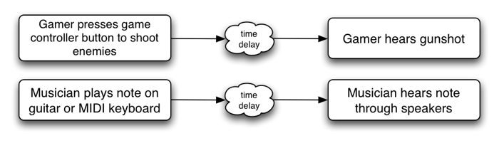
For web applications, the time delay between mouse and keyboard events
(keydown, mousedown, etc.) and a sound being heard is important.
This time delay is called latency and is caused by several factors (input
device latency, internal buffering latency, DSP processing latency, output
device latency, distance of user's ears from speakers, etc.), and is
cummulative. The larger this latency is, the less satisfying the user's
experience is going to be. In the extreme, it can make musical production or
game-play impossible. At moderate levels it can affect timing and give the
impression of sounds lagging behind or the game being non-responsive. For
musical applications the timing problems affect rhythm. For gaming, the timing
problems affect precision of gameplay. For interactive applications, it
generally cheapens the users experience much in the same way that very low
animation frame-rates do. Depending on the application, a reasonable latency
can be from as low as 3-6 milliseconds to 25-50 milliseconds.
15.2. Audio Glitching
Audio glitches are caused by an interruption of the normal continuous audio
stream, resulting in loud clicks and pops. It is considered to be a
catastrophic failure of a multi-media system and must be avoided. It can be
caused by problems with the threads responsible for delivering the audio stream
to the hardware, such as scheduling latencies caused by threads not having the
proper priority and time-constraints. It can also be caused by the audio DSP
trying to do more work than is possible in real-time given the CPU's speed.
15.3. Hardware Scalability
The system should gracefully degrade to allow audio processing under
resource constrained conditions without dropping audio frames.
First of all, it should be clear that regardless of the platform, the audio
processing load should never be enough to completely lock up the machine.
Second, the audio rendering needs to produce a clean, un-interrupted audio
stream without audible glitches.
The system should be able to run on a range of hardware, from mobile phones
and tablet devices to laptop and desktop computers. But the more limited
compute resources on a phone device make it necessary to consider techniques to
scale back and reduce the complexity of the audio rendering. For example,
voice-dropping algorithms can be implemented to reduce the total number of
notes playing at any given time.
Here's a list of some techniques which can be used to limit CPU usage:
15.3.1. CPU monitoring
In order to avoid audio breakup, CPU usage must remain below 100%.
The relative CPU usage can be dynamically measured for each AudioNode (and
chains of connected nodes) as a percentage of the rendering time quantum. In a
single-threaded implementation, overall CPU usage must remain below 100%. The
measured usage may be used internally in the implementation for dynamic
adjustments to the rendering. It may also be exposed through a
cpuUsage attribute of AudioNode for use by
JavaScript.
In cases where the measured CPU usage is near 100% (or whatever threshold is
considered too high), then an attempt to add additional AudioNodes
into the rendering graph can trigger voice-dropping.
15.3.2. Voice Dropping
Voice-dropping is a technique which limits the number of voices (notes)
playing at the same time to keep CPU usage within a reasonable range. There can
either be an upper threshold on the total number of voices allowed at any given
time, or CPU usage can be dynamically monitored and voices dropped when CPU
usage exceeds a threshold. Or a combination of these two techniques can be
applied. When CPU usage is monitored for each voice, it can be measured all the
way from the AudioSourceNode through any effect processing nodes which apply
uniquely to that voice.
When a voice is "dropped", it needs to happen in such a way that it doesn't
introduce audible clicks or pops into the rendered audio stream. One way to
achieve this is to quickly fade-out the rendered audio for that voice before
completely removing it from the rendering graph.
When it is determined that one or more voices must be dropped, there are
various strategies for picking which voice(s) to drop out of the total ensemble
of voices currently playing. Here are some of the factors which can be used in
combination to help with this decision:
- Older voices, which have been playing the longest can be dropped instead
of more recent voices.
- Quieter voices, which are contributing less to the overall mix may be
dropped instead of louder ones.
- Voices which are consuming relatively more CPU resources may be dropped
instead of less "expensive" voices.
- An AudioNode can have a
priority attribute to help determine
the relative importance of the voices.
15.3.3. Simplification of Effects
Processing
Most of the effects described in this document are relatively inexpensive
and will likely be able to run even on the slower mobile devices. However, the
convolution effect can be configured with
a variety of impulse responses, some of which will likely be too heavy for
mobile devices. Generally speaking, CPU usage scales with the length of the
impulse response and the number of channels it has. Thus, it is reasonable to
consider that impulse responses which exceed a certain length will not be
allowed to run. The exact limit can be determined based on the speed of the
device. Instead of outright rejecting convolution with these long responses, it
may be interesting to consider truncating the impulse responses to the maximum
allowed length and/or reducing the number of channels of the impulse response.
In addition to the convolution effect. The AudioPannerNode may also be
expensive if using the HRTF panning model. For slower devices, a cheaper
algorithm such as EQUALPOWER can be used to conserve compute resources.
15.3.4. Sample Rate
For very slow devices, it may be worth considering running the rendering at
a lower sample-rate than normal. For example, the sample-rate can be reduced
from 44.1KHz to 22.05KHz. This decision must be made when the
AudioContext is created, because changing the sample-rate
on-the-fly can be difficult to implement and will result in audible glitching
when the transition is made.
15.3.5. Pre-flighting
It should be possible to invoke some kind of "pre-flighting" code (through
JavaScript) to roughly determine the power of the machine. The JavaScript code
can then use this information to scale back any more intensive processing it
may normally run on a more powerful machine. Also, the underlying
implementation may be able to factor in this information in the voice-dropping
algorithm.
TODO: add specification and more detail here
15.3.6. Authoring for different
user agents
JavaScript code can use information about user-agent to scale back any more
intensive processing it may normally run on a more powerful machine.
15.3.7. Scalability of
Direct JavaScript Synthesis / Processing
Any audio DSP / processing code done directly in JavaScript should also be
concerned about scalability. To the extent possible, the JavaScript code itself
needs to monitor CPU usage and scale back any more ambitious processing when
run on less powerful devices. If it's an "all or nothing" type of processing,
then user-agent check or pre-flighting should be done to avoid generating an
audio stream with audio breakup.
While processing audio in JavaScript, it is extremely challenging to get
reliable, glitch-free audio while achieving a reasonably low-latency,
especially under heavy processor load.
- JavaScript is very much slower than heavily optimized C++ code and is not
able to take advantage of SSE optimizations and multi-threading which is
critical for getting good performance on today's processors. Optimized
native code can be on the order of twenty times faster for processing FFTs
as compared with JavaScript. It is not efficient enough for heavy-duty
processing of audio such as convolution and 3D spatialization of large
numbers of audio sources.
- setInterval() and XHR handling will steal time from the audio processing.
In a reasonably complex game, some JavaScript resources will be needed for
game physics and graphics. This creates challenges because audio rendering
is deadline driven (to avoid glitches and get low enough latency).
- JavaScript does not run in a real-time processing thread and thus can be
pre-empted by many other threads running on the system.
- Garbage Collection (and autorelease pools on Mac OS X) can cause
unpredictable delay on a JavaScript thread.
- Multiple JavaScript contexts can be running on the main thread, stealing
time from the context doing the processing.
- Other code (other than JavaScript) such as page rendering runs on the
main thread.
- Locks can be taken and memory is allocated on the JavaScript thread. This
can cause additional thread preemption.
The problems are even more difficult with today's generation of mobile devices
which have processors with relatively poor performance and power consumption /
battery-life issues.
16. Example Applications
This section is informative.
Please see the demo
page for working examples.
Here are some of the types of applications a web audio system should be able
to support:
Basic Sound Playback
Simple and low-latency
playback of sound effects in response to simple user actions such as mouse
click, roll-over, key press.
3D Environments and Games
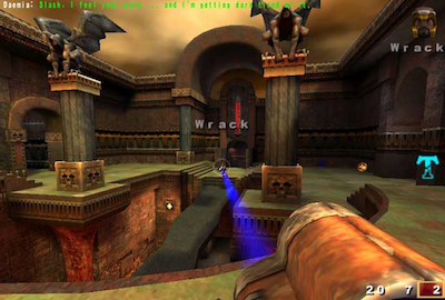
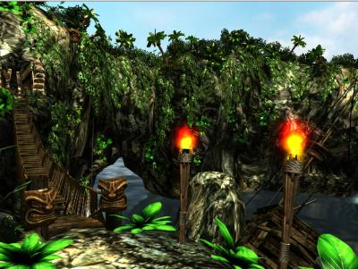
An HTML5
version of Quake has already been created. Audio features such as 3D
spatialization and convolution for room simulation could be used to great
effect.
3D environments with audio are common in games made for desktop applications
and game consoles. Imagine a 3D island environment with spatialized audio,
seagulls flying overhead, the waves crashing against the shore, the crackling
of the fire, the creaking of the bridge, and the rustling of the trees in the
wind. The sounds can be positioned naturally as one moves through the scene.
Even going underwater, low-pass filters can be tweaked for just the right
underwater sound.
Box2D is an interesting open-source
library for 2D game physics. It has various implementations, including one
based on Canvas 2D. A demo has been created with dynamic sound effects for each
of the object collisions, taking into account the velocities vectors and
positions to spatialize the sound events, and modulate audio effect parameters
such as filter cutoff.
A virtual pool game with multi-sampled sound effects has also been created.
Musical Applications
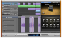
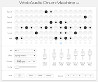
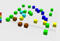
Many music composition and production applications are possible. Applications
requiring tight scheduling of audio events can be implemented and can be both
educational and entertaining. Drum machines, digital DJ applications, and even
timeline-based digital music production software with some of the features of
GarageBand can be
written.
Music Visualizers

When combined with WebGL GLSL shaders, realtime analysis data can be presented
in entertaining ways. These can be as advanced as any found in iTunes.
Educational Applications
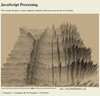
A variety of educational applications can be written, illustrating concepts
in music theory and computer music synthesis and processing.
Artistic Audio Exploration
There are many creative possibilites for artistic sonic environments for
installation pieces.
17. Security Considerations
This section is informative.
18. Privacy Considerations
This section is informative. When giving various information on
available AudioNodes, the Web Audio API potentially exposes information on
characteristic features of the client (such as audio hardware sample-rate) to
any page that makes use of the AudioNode interface. Additionally, timing
information can be collected through the RealtimeAnalyzerNode or
JavaScriptAudioNode interface. The information could subsequently be used to
create a fingerprint of the client.
Currently audio input is not specified in this document, but it will involve
gaining access to the client machine's audio input or microphone. This will
require asking the user for permission in an appropriate way, probably via the
getUserMedia()
API.
B.Acknowledgements
Special thanks to the W3C Audio
Working Group. Members of the Working Group are (at the time of writing,
and by alphabetical order):
Berkovitz, Joe (public Invited expert);Cardoso, Gabriel (INRIA);Carlson, Eric
(Apple, Inc.);Gregan, Matthew (Mozilla Foundation);Jägenstedt, Philip (Opera
Software);Kalliokoski, Jussi (public Invited expert);Lowis, Chris (British
Broadcasting Corporation);MacDonald, Alistair (W3C Invited Experts);Michel,
Thierry (W3C/ERCIM);Noble, Jer (Apple, Inc.);O'Callahan, Robert(Mozilla
Foundation);Paradis, Matthew (British Broadcasting Corporation);Raman, T.V.
(Google, Inc.);Rogers, Chris (Google, Inc.);Schepers, Doug (W3C/MIT);Shires,
Glen (Google, Inc.);Smith, Michael (W3C/Keio);Thereaux, Olivier (British
Broadcasting Corporation);Wei, James (Intel Corporation);Wilson, Chris (Google,
Inc.);
C. Web Audio API Change Log
date:        Tue Jun 26 15:56:31 2012 -0700
* add MediaStreamAudioSourceNode

date:        Mon Jun 18 13:26:21 2012 -0700
* minor formatting fix

date:        Mon Jun 18 13:19:34 2012 -0700
* Add details for azimuth/elevation calculation

date:        Fri Jun 15 17:35:27 2012 -0700
* Add equal-power-panning details

date:        Thu Jun 14 17:31:16 2012 -0700
* Add equations for distance models

date:        Wed Jun 13 17:40:49 2012 -0700
* Bug 17334: Add precise equations for AudioParam.setTargetValueAtTime()

date:        Fri Jun 08 17:44:26 2012 -0700
* fix small typo

date:        Fri Jun 08 16:54:04 2012 -0700
* Bug 17413: AudioBuffers' relationship to AudioContext

date:        Fri Jun 08 16:05:45 2012 -0700
* Bug 17359: Add much more detail about ConvolverNode

date:        Fri Jun 08 12:59:29 2012 -0700
* minor formatting fix

date:        Fri Jun 08 12:57:11 2012 -0700
* Bug 17335: Add much more technical detail to setValueCurveAtTime()

date:        Wed Jun 06 16:34:43 2012 -0700
*Add much more detail about parameter automation, including an example

date:        Mon Jun 04 17:25:08 2012 -0700
* ISSUE-85: Oscillator folding considerations

date:        Mon Jun 04 17:02:20 2012 -0700
* ISSUE-45: AudioGain scale underdefined

date:        Mon Jun 04 16:40:43 2012 -0700
* ISSUE-41: AudioNode as input to AudioParam underdefined

date:        Mon Jun 04 16:14:48 2012 -0700
* ISSUE-20: Relationship to currentTime

date:        Mon Jun 04 15:48:49 2012 -0700
* ISSUE-94: Dynamic Lifetime

date:        Mon Jun 04 13:59:31 2012 -0700
* ISSUE-42: add more detail about AudioParam sampling and block processing

date:        Mon Jun 04 12:28:48 2012 -0700
* fix typo - minor edits

date:        Thu May 24 18:01:20 2012 -0700
* ISSUE-69: add implementors guide for linear convolution

date:        Thu May 24 17:35:45 2012 -0700
* ISSUE-49: better define AudioBuffer audio data access

date:        Thu May 24 17:15:29 2012 -0700
* fix small typo

date:        Thu May 24 17:13:34 2012 -0700
* ISSUE-24: define circular routing behavior

date:        Thu May 24 16:35:24 2012 -0700
* ISSUE-42: specify a-rate or k-rate for each AudioParam

date:        Fri May 18 17:01:36 2012 -0700
* ISSUE-53: noteOn and noteOff interaction

date:        Fri May 18 16:33:29 2012 -0700
* ISSUE-34: Remove .name attribute from AudioParam

date:        Fri May 18 16:27:19 2012 -0700
* ISSUE-33: Add maxNumberOfChannels attribute to AudioDestinationNode

date:        Fri May 18 15:50:08 2012 -0700
* ISSUE-19: added more info about AudioBuffer - IEEE 32-bit

date:        Fri May 18 15:37:27 2012 -0700
* ISSUE-29: remove reference to webkitAudioContext

date:        Fri Apr 27 12:36:54 2012 -0700
* fix two small typos reported by James Wei

date:        Tue Apr 24 12:27:11 2012 -0700
* small cleanup to AudioChannelSplitter and AudioChannelMerger

date:        Tue Apr 17 11:35:56 2012 -0700
* small fix to createWaveTable()

date:        Tue Apr 13 2012
* Cleanup AudioNode connect() and disconnect() method descriptions.
* Add AudioNode connect() to AudioParam method.

date:        Tue Apr 13 2012
* Add Oscillator and WaveTable
* Define default values for optional arguments in createJavaScriptNode(), createChannelSplitter(), createChannelMerger()
* Define default filter type for BiquadFilterNode as LOWPASS

date:        Tue Apr 11 2012
* add AudioContext .activeSourceCount attribute
* createBuffer() methods can throw exceptions
* add AudioContext method createMediaElementSource()
* update AudioContext methods createJavaScriptNode() (clean up description of parameters)
* update AudioContext method createChannelSplitter() (add numberOfOutputs parameter)
* update AudioContext method createChannelMerger() (add numberOfInputs parameter)
* update description of out-of-bounds AudioParam values (exception will not be thrown)
* remove AudioBuffer .gain attribute
* remove AudioBufferSourceNode .gain attribute
* remove AudioListener .gain attribute
* add AudioBufferSourceNode .playbackState attribute and state constants
* RealtimeAnalyserNode no longer requires its output be connected to anything
* update AudioChannelMerger section describing numberOfOutputs (defaults to 6 but settable in constructor)
* update AudioChannelSplitter section describing numberOfInputs (defaults to 6 but settable in constructor)
* add note in Spatialization sections about potential to get arbitrary convolution matrixing

date:        Tue Apr 10 2012
* Rebased editor's draft document based on edits from Thierry Michel (from 2nd public working draft).

date:        Tue Mar 13 12:13:41 2012 -0100
*  fixed all the HTML errors
*  added ids to all Headings
*  added alt attribute to all img
*  fix broken anchors
*  added a new status of this document section
*  added mandatory spec headers
*  generated a new table of content
*  added a Reference section
*  added an Acknowledgments section
*  added a Web Audio API Change Log

date:        Fri Mar 09 15:12:42 2012 -0800
* add optional maxDelayTime argument to createDelayNode()
* add more detail about playback state to AudioBufferSourceNode
* upgrade noteOn(), noteGrainOn(), noteOff() times to double from float

date:        Mon Feb 06 16:52:39 2012 -0800
* Cleanup JavaScriptAudioNode section
* Add distance model constants for AudioPannerNode according to the OpenAL spec
* Add .normalize attribute to ConvolverNode
* Add getFrequencyResponse() method to BiquadFilterNode
* Tighten up the up-mix equations

date:        Fri Nov 04 15:40:58 2011 -0700
summary:     Add more technical detail to BiquadFilterNode description (contributed by Raymond Toy)

date:        Sat Oct 15 19:08:15 2011 -0700
summary:     small edits to the introduction

date:        Sat Oct 15 19:00:15 2011 -0700
summary:     initial commit

date:        Tue Sep 13 12:49:11 2011 -0700
summary:     add convolution reverb design document

date:        Mon Aug 29 17:05:58 2011 -0700
summary:     document the decodeAudioData() method

date:        Mon Aug 22 14:36:33 2011 -0700
summary:     fix broken MediaElementAudioSourceNode link

date:        Mon Aug 22 14:33:57 2011 -0700
summary:     refine section describing integration with HTMLMediaElement

date:        Mon Aug 01 12:05:53 2011 -0700
summary:     add Privacy section

date:        Mon Jul 18 17:53:50 2011 -0700
summary:     small update - tweak musical applications thumbnail images

date:        Mon Jul 18 17:23:00 2011 -0700
summary:     initial commit of Web Audio API specification