This chapter describes SVG's declarative filter effects feature set, which when combined with the 2D power of SVG can describe much of the common artwork on the Web in such a way that client-side generation and alteration can be performed easily. In addition, the ability to apply filter effects to SVG graphics elements and container elements helps to maintain the semantic structure of the document, instead of resorting to images which aside from generally being a fixed resolution tend to obscure the original semantics of the elements they replace. This is especially true for effects applied to text.
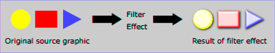
A filter effect consists of a series of graphics operations that are applied to a given source graphic to produce a modified graphical result. The result of the filter effect is rendered to the target device instead of the original source graphic. The following illustrates the process:
View this example as SVG (SVG-enabled browsers only)
Filter effects are defined by 'filter' elements. To apply a filter effect to a graphics element or a container element, you set the value of the 'filter' property on the given element such that it references the filter effect.
Each 'filter' element contains a set of filter primitives as its children. Each filter primitive performs a single fundamental graphical operation (e.g., a blur or a lighting effect) on one or more inputs, producing a graphical result. Because most of the filter primitives represent some form of image processing, in most cases the output from a filter primitive is a single RGBA image.
The original source graphic or the result from a filter primitive can be used as input into one or more other filter primitives. A common application is to use the source graphic multiple times. For example, a simple filter could replace one graphic by two by adding a black copy of original source graphic offset to create a drop shadow. In effect, there are now two layers of graphics, both with the same original source graphics.
When applied to container elements such as 'g', the 'filter' property applies to the contents of the group as a whole. The group's children do not render to the screen directly; instead, the graphics commands necessary to render the children are stored temporarily. Typically, the graphics commands are executed as part of the processing of the referenced 'filter' element via use of the keywords SourceGraphic or SourceAlpha. Filter effects can be applied to container elements with no content (e.g., an empty 'g' element), in which case the SourceGraphic or SourceAlpha consist of a transparent black rectangle that is the size of the filter effects region.
Sometimes filter primitives result in undefined pixels. For example, filter primitive 'feOffset' can shift an image down and to the right, leaving undefined pixels at the top and left. In these cases, the undefined pixels are set to transparent black.
The following shows an example of a filter effect.
Example filters01 - introducing filter effects.
<?xml version="1.0"?>
<!DOCTYPE svg PUBLIC "-//W3C//DTD SVG 20010904//EN"
              "http://www.w3.org/TR/2001/REC-SVG-20010904/DTD/svg10.dtd">
<svg width="7.5cm" height="5cm" viewBox="0 0 200 120"
     xmlns="http://www.w3.org/2000/svg">
  <title>Example filters01.svg - introducing filter effects</title>
  <desc>An example which combines multiple filter primitives
        to produce a 3D lighting effect on a graphic consisting
        of the string "SVG" sitting on top of oval filled in red
        and surrounded by an oval outlined in red.</desc>
  <defs>
    <filter id="MyFilter" filterUnits="userSpaceOnUse" x="0" y="0" width="200" height="120">
      <feGaussianBlur in="SourceAlpha" stdDeviation="4" result="blur"/>
      <feOffset in="blur" dx="4" dy="4" result="offsetBlur"/>
      <feSpecularLighting in="blur" surfaceScale="5" specularConstant=".75"
                          specularExponent="20" lighting-color="#bbbbbb"
                          result="specOut">
        <fePointLight x="-5000" y="-10000" z="20000"/>
      </feSpecularLighting>
      <feComposite in="specOut" in2="SourceAlpha" operator="in" result="specOut"/>
      <feComposite in="SourceGraphic" in2="specOut" operator="arithmetic"
                   k1="0" k2="1" k3="1" k4="0" result="litPaint"/>
      <feMerge>
        <feMergeNode in="offsetBlur"/>
        <feMergeNode in="litPaint"/>
      </feMerge>
    </filter>
  </defs>
  <rect x="1" y="1" width="198" height="118" fill="#888888" stroke="blue" />
  <g filter="url(#MyFilter)" >
	  <g>
      <path fill="none" stroke="#D90000" stroke-width="10"
            d="M50,90 C0,90 0,30 50,30 L150,30 C200,30 200,90 150,90 z" />
      <path fill="#D90000"
            d="M60,80 C30,80 30,40 60,40 L140,40 C170,40 170,80 140,80 z" />
      <g fill="#FFFFFF" stroke="black" font-size="45" font-family="Verdana" >
        <text x="52" y="76">SVG</text>
      </g>
    </g>
  </g>
</svg>
 |
View this example as SVG (SVG-enabled browsers only)
The filter effect used in the example above is repeated here with reference numbers in the left column before each of the six filter primitives:
1 2 3 4 5 6 |
<filter id="MyFilter" filterUnits="userSpaceOnUse" x="0" y="0" width="200" height="120">
  <desc>Produces a 3D lighting effect.</desc>
  <feGaussianBlur in="SourceAlpha" stdDeviation="4" result="blur"/>
  <feOffset in="blur" dx="4" dy="4" result="offsetBlur"/>
  <feSpecularLighting in="blur" surfaceScale="5" specularConstant=".75"
                      specularExponent="20" lighting-color="#bbbbbb"
                      result="specOut">
    <fePointLight x="-5000" y="-10000" z="20000"/>
  </feSpecularLighting>
  <feComposite in="specOut" in2="SourceAlpha" operator="in" result="specOut"/>
  <feComposite in="SourceGraphic" in2="specOut" operator="arithmetic"
               k1="0" k2="1" k3="1" k4="0" result="litPaint"/>
  <feMerge>
    <feMergeNode in="offsetBlur"/>
    <feMergeNode in="litPaint"/>
  </feMerge>
</filter>
|
The following pictures show the intermediate image results from each of the six filter elements:
|
|
|
|
|||
|
|
|
The description of the 'filter' element follows:
<!ENTITY % filterExt "" > <!ELEMENT filter (%descTitleMetadata;,(feBlend|feFlood| feColorMatrix|feComponentTransfer| feComposite|feConvolveMatrix|feDiffuseLighting|feDisplacementMap| feGaussianBlur|feImage|feMerge| feMorphology|feOffset|feSpecularLighting| feTile|feTurbulence| animate|set %filterExt;)*) > <!ATTLIST filter %stdAttrs; %xlinkRefAttrs; xlink:href %URI; #IMPLIED %langSpaceAttrs; externalResourcesRequired %Boolean; #IMPLIED class %ClassList; #IMPLIED style %StyleSheet; #IMPLIED %PresentationAttributes-All; filterUnits (userSpaceOnUse | objectBoundingBox) #IMPLIED primitiveUnits (userSpaceOnUse | objectBoundingBox) #IMPLIED x %Coordinate; #IMPLIED y %Coordinate; #IMPLIED width %Length; #IMPLIED height %Length; #IMPLIED filterRes %NumberOptionalNumber; #IMPLIED > |
Attribute definitions:
Properties inherit into the 'filter' element from its ancestors; properties do not inherit from the element referencing the 'filter' element.
'filter' elements are never rendered directly; their only usage is as something that can be referenced using the 'filter' property. The 'display' property does not apply to the 'filter' element; thus, 'filter' elements are not directly rendered even if the 'display' property is set to a value other than none, and 'filter' elements are available for referencing even when the 'display' property on the 'filter' element or any of its ancestors is set to none.
The description of the 'filter' property is as follows:
| Value: | <uri> | none | inherit |
| Initial: | none |
| Applies to: | container elements and graphics elements |
| Inherited: | no |
| Percentages: | N/A |
| Media: | visual |
| Animatable: | yes |
A 'filter' element can define a region on the canvas to which a given filter effect applies and can provide a resolution for any intermediate continuous tone images used to process any raster-based filter primitives. The 'filter' element has the following attributes which work together to define the filter effects region:
x-pixels [y-pixels])
indicates the width and height of the intermediate images in pixels.
If not provided, then a reasonable default resolution appropriate for
the target device will be used. (For displays, an appropriate display
resolution, preferably the current display's pixel resolution, is the
default.
For printing, an appropriate common printer resolution, such as 400dpi,
is the default.)Note that both of the two possible value for filterUnits (i.e., objectBoundingBox and userSpaceOnUse) result in a filter region whose coordinate system has its X-axis and Y-axis each parallel to the X-axis and Y-axis, respectively, of the user coordinate system for the element to which the filter will be applied.
Sometimes implementers can achieve faster performance when the filter region can be mapped directly to device pixels; thus, for best performance on display devices, it is suggested that authors define their region such that SVG user agent can align the filter region pixel-for-pixel with the background. In particular, for best filter effects performance, avoid rotating or skewing the user coordinate system. Explicit values for attribute filterRes can either help or harm performance. If filterRes is smaller than the automatic (i.e., default) filter resolution, then filter effect might have faster performance (usually at the expense of quality). If filterRes is larger than the automatic (i.e., default) filter resolution, then filter effects performance will usually be slower.
It is often necessary to provide padding space because the filter effect might impact bits slightly outside the tight-fitting bounding box on a given object. For these purposes, it is possible to provide negative percentage values for x, y and percentages values greater than 100% for width, height. This, for example, is why the defaults for the filter effects region are x="-10%" y="-10%" width="120%" height="120%".
Two possible pseudo input images for filter effects are BackgroundImage and BackgroundAlpha, which each represent an image snapshot of the canvas under the filter region at the time that the 'filter' element is invoked. BackgroundImage represents both the color values and alpha channel of the canvas (i.e., RGBA pixel values), whereas BackgroundAlpha represents only the alpha channel.
Implementations of SVG user agents often will need to maintain supplemental background image buffers in order to support the BackgroundImage and BackgroundAlpha pseudo input images. Sometimes, the background image buffers will contain an in-memory copy of the accumulated painting operations on the current canvas.
Because in-memory image buffers can take up significant system resources, SVG content must explicitly indicate to the SVG user agent that the document needs access to the background image before BackgroundImage and BackgroundAlpha pseudo input images can be used. The property which enables access to the background image is 'enable-background':
| Value: | accumulate | new [ <x> <y> <width> <height> ] | inherit |
| Initial: | accumulate |
| Applies to: | container elements |
| Inherited: | no |
| Percentages: | N/A |
| Media: | visual |
| Animatable: | no |
'enable-background' is only applicable to container elements and specifies how the SVG user agents manages the accumulation of the background image.
A value of new indicates two things:
A meaning of enable-background: accumulate (the initial/default value) depends on context:
If a filter effect specifies either the BackgroundImage or the BackgroundAlpha pseudo input images and no ancestor container element has a property value of 'enable-background:new', then the background image request is technically in error. Processing will proceed without interruption (i.e., no error message) and a transparent black image shall be provided in response to the request.
The optional <x>,<y>,<width>,<height>
parameters on the new
value indicate the subregion of
the container element's
user space
where access to the background image is allowed to happen.
These parameters enable the SVG user agent potentially to allocate
smaller temporary image buffers than the default values, which might
require the SVG user agent to allocate buffers as large as the current
viewport.
Thus, the values <x>,<y>,<width>,<height> act
as a clipping rectangle on the background image canvas.
Negative values for <width> or <height>
are an error (see Error processing).
If more than zero but less than four of the values
<x>,<y>,<width> and <height> are specified
or if zero values are specified for <width> or <height>, BackgroundImage
and BackgroundAlpha are processed as if
background image processing were not enabled.
Assume you have an element E in the document and that E has a series of ancestors A1 (its immediate parent), A2, etc. (Note: A0 is E.) Each ancestor Ai will have a corresponding temporary background image offscreen buffer BUFi. The contents of the background image available to a 'filter' referenced by E is defined as follows:
Example enable-background-01 illustrates the rules for background image processing.
<?xml version="1.0" standalone="no"?>
<!DOCTYPE svg PUBLIC "-//W3C//DTD SVG 20010904//EN"
  "http://www.w3.org/TR/2001/REC-SVG-20010904/DTD/svg10.dtd">
<svg width="13.5cm" height="2.7cm" viewBox="0 0 1350 270"
     xmlns="http://www.w3.org/2000/svg">
  <title>Example enable-background01</title>
  <desc>This test case shows five pictures which illustrate the rules
        for background image processing.</desc>

  <defs>
    <filter id="ShiftBGAndBlur"
            filterUnits="userSpaceOnUse" x="0" y="0" width="1200" height="400">
      <desc>
        This filter discards the SourceGraphic, if any, and just produces
        a result consisting of the BackgroundImage shifted down 125 units
        and then blurred.
      </desc>
      <feOffset in="BackgroundImage" dx="0" dy="125" />
      <feGaussianBlur stdDeviation="8" />
    </filter>
    <filter id="ShiftBGAndBlur_WithSourceGraphic"
            filterUnits="userSpaceOnUse" x="0" y="0" width="1200" height="400">
      <desc>
        This filter takes the BackgroundImage, shifts it down 125 units, blurs it,
        and then renders the SourceGraphic on top of the shifted/blurred background.
      </desc>
      <feOffset in="BackgroundImage" dx="0" dy="125" />
      <feGaussianBlur stdDeviation="8" result="blur" />
      <feMerge>
        <feMergeNode in="blur"/>
        <feMergeNode in="SourceGraphic"/>
      </feMerge>
    </filter>
  </defs>

  <g transform="translate(0,0)">
    <desc>The first picture is our reference graphic without filters.</desc>
    <rect x="25" y="25" width="100" height="100" fill="red"/>
    <g opacity=".5">
      <circle cx="125" cy="75" r="45" fill="green"/>
      <polygon points="160,25 160,125 240,75" fill="blue"/>
    </g>
    <rect x="5" y="5" width="260" height="260" fill="none" stroke="blue"/>
  </g>

  <g enable-background="new" transform="translate(270,0)">
    <desc>The second adds an empty 'g' element which invokes ShiftBGAndBlur.</desc>
    <rect x="25" y="25" width="100" height="100" fill="red"/>
    <g opacity=".5">
      <circle cx="125" cy="75" r="45" fill="green"/>
      <polygon points="160,25 160,125 240,75" fill="blue"/>
    </g>
    <g filter="url(#ShiftBGAndBlur)"/>
    <rect x="5" y="5" width="260" height="260" fill="none" stroke="blue"/>
  </g>

  <g enable-background="new" transform="translate(540,0)">
    <desc>The third invokes ShiftBGAndBlur on the inner group.</desc>
    <rect x="25" y="25" width="100" height="100" fill="red"/>
    <g filter="url(#ShiftBGAndBlur)" opacity=".5">
      <circle cx="125" cy="75" r="45" fill="green"/>
      <polygon points="160,25 160,125 240,75" fill="blue"/>
    </g>
    <rect x="5" y="5" width="260" height="260" fill="none" stroke="blue"/>
  </g>

  <g enable-background="new" transform="translate(810,0)">
    <desc>The fourth invokes ShiftBGAndBlur on the triangle.</desc>
    <rect x="25" y="25" width="100" height="100" fill="red"/>
    <g opacity=".5">
      <circle cx="125" cy="75" r="45" fill="green"/>
      <polygon points="160,25 160,125 240,75" fill="blue"
               filter="url(#ShiftBGAndBlur)"/>
    </g>
    <rect x="5" y="5" width="260" height="260" fill="none" stroke="blue"/>
  </g>

  <g enable-background="new" transform="translate(1080,0)">
    <desc>The fifth invokes ShiftBGAndBlur_WithSourceGraphic on the triangle.</desc>
    <rect x="25" y="25" width="100" height="100" fill="red"/>
    <g opacity=".5">
      <circle cx="125" cy="75" r="45" fill="green"/>
      <polygon points="160,25 160,125 240,75" fill="blue"
               filter="url(#ShiftBGAndBlur_WithSourceGraphic)"/>
    </g>
    <rect x="5" y="5" width="260" height="260" fill="none" stroke="blue"/>
  </g>
</svg>
 |
View this example as SVG (SVG-enabled browsers only)
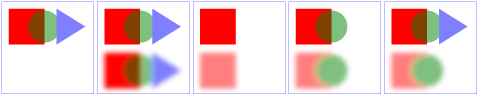
The example above contains five parts, described as follows:
This section describes the various filter primtives that can be assembled to achieve a particular filter effect.
Unless otherwise stated, all image filters operate on premultiplied RGBA samples. Filters which work more naturally on non-premultiplied data (feColorMatrix and feComponentTransfer) will temporarily undo and redo premultiplication as specified. All raster effect filtering operations take 1 to N input RGBA images, additional attributes as parameters, and produce a single output RGBA image.
The RGBA result from each filter primitive will be clamped into the allowable ranges for colors and opacity values. Thus, for example, the result from a given filter primitive will have any negative color values or opacity values adjusted up to color/opacity of zero.
The color space in which a particular filter primitive performs its operations is determined by the value of property 'color-interpolation-filters' on the given filter primitive. A different property, 'color-interpolation' determines the color space for other color operations. Because these two properties have different initial values ('color-interpolation-filters' has an initial value of linearRGB whereas 'color-interpolation' has an initial value of sRGB), in some cases to achieve certain results (e.g., when coordinating gradient interpolation with a filtering operation) it will be necessary to explicitly set 'color-interpolation' to linearRGB or 'color-interpolation-filters' to sRGB on particular elements. Note that the examples below do not explicitly set either 'color-interpolation' or 'color-interpolation-filters', so the initial values for these properties apply to the examples.
The following attributes are available for most of the filter primitives:
<!ENTITY % filter_primitive_attributes
  "x %Coordinate; #IMPLIED
   y %Coordinate; #IMPLIED
   width %Length; #IMPLIED
   height %Length; #IMPLIED
   result CDATA #IMPLIED" >

<!ENTITY % filter_primitive_attributes_with_in
  "%filter_primitive_attributes;
   in CDATA #IMPLIED">
Attribute definitions:
All filter primitives have attributes x, y, width and height which identify a subregion which restricts calculation and rendering of the given filter primitive. These attributes are defined according to the same rules as other filter primitives' coordinate and length attributes and thus represent values in the coordinate system established by attribute primitiveUnits on the 'filter' element.
x, y, width and height default to the union (i.e., tightest fitting bounding box) of the subregions defined for all referenced nodes. If there are no referenced nodes (e.g., for 'feImage' or 'feTurbulence'), or one or more of the referenced nodes is a standard input (one of SourceGraphic, SourceAlpha, BackgroundImage, BackgroundAlpha, FillPaint or StrokePaint), or for 'feTile' (which is special because its principal function is to replicate the referenced node in X and Y and thereby produce a usually larger result), the default subregion is 0%,0%,100%,100%, where percentages are relative to the dimensions of the filter region.
x, y, width and height act as a hard clip clipping rectangle.
All intermediate offscreens are defined to not exceed the intersection of x, y, width and height with the filter region. The filter region and any of the x, y, width and height subregions are to be set up such that all offscreens are made big enough to accommodate any pixels which even partly intersect with either the filter region or the x,y,width,height subregions.
'feTile' references a previous filter primitive and then stitches the tiles together based on the x, y, width and height values of the referenced filter primitive in order to fill its own filter primitive subregion.
The following sections define the elements that define a light source, 'feDistantLight', 'fePointLight' and 'feSpotLight', and property 'lighting-color', which defines the color of the light.
<!ELEMENT feDistantLight (animate|set)* > <!ATTLIST feDistantLight %stdAttrs; azimuth %Number; #IMPLIED elevation %Number; #IMPLIED > |
Attribute definitions:
<!ELEMENT fePointLight (animate|set)* > <!ATTLIST fePointLight %stdAttrs; x %Number; #IMPLIED y %Number; #IMPLIED z %Number; #IMPLIED > |
Attribute definitions:
<!ELEMENT feSpotLight (animate|set)* > <!ATTLIST feSpotLight %stdAttrs; x %Number; #IMPLIED y %Number; #IMPLIED z %Number; #IMPLIED pointsAtX %Number; #IMPLIED pointsAtY %Number; #IMPLIED pointsAtZ %Number; #IMPLIED specularExponent %Number; #IMPLIED limitingConeAngle %Number; #IMPLIED > |
Attribute definitions:
The 'lighting-color' property defines the color of the light source for filter primitives 'feDiffuseLighting' and 'feSpecularLighting'.
| Value: | currentColor | <color> [icc-color(<name>[,<icccolorvalue>]*)] | inherit |
| Initial: | white |
| Applies to: | 'feDiffuseLighting' and 'feSpecularLighting' elements |
| Inherited: | no |
| Percentages: | N/A |
| Media: | visual |
| Animatable: | yes |
This filter composites two objects together using commonly used imaging software blending modes. It performs a pixel-wise combination of two input images.
<!ELEMENT feBlend (animate|set)* > <!ATTLIST feBlend %stdAttrs; %PresentationAttributes-FilterPrimitives; %filter_primitive_attributes_with_in; in2 CDATA #REQUIRED mode (normal | multiply | screen | darken | lighten) "normal" > |
Attribute definitions:
For all feBlend modes, the result opacity is computed as follows:
qr = 1 - (1-qa)*(1-qb)
For the compositing formulas below, the following definitions apply:
cr = Result color (RGB) - premultiplied
qa = Opacity value at a given pixel for image A
qb = Opacity value at a given pixel for image B
ca = Color (RGB) at a given pixel for image A - premultiplied
cb = Color (RGB) at a given pixel for image B - premultiplied
The following table provides the list of available image blending modes:
| Image Blending Mode | Formula for computing result color |
| normal | cr = (1 - qa) * cb + ca |
| multiply | cr = (1-qa)*cb + (1-qb)*ca + ca*cb |
| screen | cr = cb + ca - ca * cb |
| darken | cr = Min ((1 - qa) * cb + ca, (1 - qb) * ca + cb) |
| lighten | cr = Max ((1 - qa) * cb + ca, (1 - qb) * ca + cb) |
'normal' blend mode is equivalent to operator="over" on the 'feComposite' filter primitive, matches the blending method used by 'feMerge' and matches the simple alpha compositing technique used in SVG for all compositing outside of filter effects.
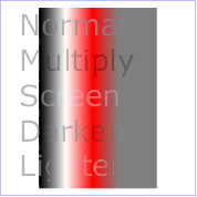
Example feBlend shows examples of the five blend modes.
<?xml version="1.0"?>
<!DOCTYPE svg PUBLIC "-//W3C//DTD SVG 20010904//EN"
          "http://www.w3.org/TR/2001/REC-SVG-20010904/DTD/svg10.dtd">
<svg width="5cm" height="5cm" viewBox="0 0 500 500"
     xmlns="http://www.w3.org/2000/svg">
  <title>Example feBlend - Examples of feBlend modes</title>
  <desc>Five text strings blended into a gradient,
        with one text string for each of the five feBlend modes.</desc>
  <defs>
    <linearGradient id="MyGradient" gradientUnits="userSpaceOnUse"
            x1="100" y1="0" x2="300" y2="0">
      <stop offset="0" stop-color="#000000" />
      <stop offset=".33" stop-color="#ffffff" />
      <stop offset=".67" stop-color="#ff0000" />
      <stop offset="1" stop-color="#808080" />
    </linearGradient>
    <filter id="Normal">
      <feBlend mode="normal" in2="BackgroundImage" in="SourceGraphic"/>
    </filter>
    <filter id="Multiply">
      <feBlend mode="multiply" in2="BackgroundImage" in="SourceGraphic"/>
    </filter>
    <filter id="Screen">
      <feBlend mode="screen" in2="BackgroundImage" in="SourceGraphic"/>
    </filter>
    <filter id="Darken">
      <feBlend mode="darken" in2="BackgroundImage" in="SourceGraphic"/>
    </filter>
    <filter id="Lighten">
      <feBlend mode="lighten" in2="BackgroundImage" in="SourceGraphic"/>
    </filter>
  </defs>
  <rect fill="none" stroke="blue"
        x="1" y="1" width="498" height="498"/>
  <g enable-background="new" >
    <rect x="100" y="20" width="300" height="460" fill="url(#MyGradient)" />
    <g font-family="Verdana" font-size="75" fill="#888888" fill-opacity=".6" >
      <text x="50" y="90" filter="url(#Normal)" >Normal</text>
      <text x="50" y="180" filter="url(#Multiply)" >Multiply</text>
      <text x="50" y="270" filter="url(#Screen)" >Screen</text>
      <text x="50" y="360" filter="url(#Darken)" >Darken</text>
      <text x="50" y="450" filter="url(#Lighten)" >Lighten</text>
    </g>
  </g>
</svg>
 |
View this example as SVG (SVG-enabled browsers only)
This filter applies a matrix transformation:
| R' |     | a00 a01 a02 a03 a04 |   | R |

| G' |     | a10 a11 a12 a13 a14 |   | G |

| B' |  =  | a20 a21 a22 a23 a24 | * | B |

| A' |     | a30 a31 a32 a33 a34 |   | A |

| 1  |     |  0   0   0   0   1  |   | 1 |
on the RGBA color and alpha values of every pixel on the input graphics to produce a result with a new set of RGBA color and alpha values.
The calculations are performed on non-premultiplied color values. If the input graphics consists of premultiplied color values, those values are automatically converted into non-premultiplied color values for this operation.
These matrices often perform an identity mapping in the alpha channel. If that is the case, an implementation can avoid the costly undoing and redoing of the premultiplication for all pixels with A = 1.
<!ELEMENT feColorMatrix (animate|set)* > <!ATTLIST feColorMatrix %stdAttrs; %PresentationAttributes-FilterPrimitives; %filter_primitive_attributes_with_in; type (matrix | saturate | hueRotate | luminanceToAlpha) "matrix" values CDATA #IMPLIED > |
Attribute definitions:
type="matrix"
values="1 0 0 0 0  0 1 0 0 0  0 0 1 0 0  0 0 0 1 0"
| R' |     |0.213+0.787s  0.715-0.715s  0.072-0.072s 0  0 |   | R |

| G' |     |0.213-0.213s  0.715+0.285s  0.072-0.072s 0  0 |   | G |

| B' |  =  |0.213-0.213s  0.715-0.715s  0.072+0.928s 0  0 | * | B |

| A' |     |           0            0             0  1  0 |   | A |

| 1  |     |           0            0             0  0  1 |   | 1 |
| R' |     | a00  a01  a02  0  0 |   | R |

| G' |     | a10  a11  a12  0  0 |   | G |

| B' |  =  | a20  a21  a22  0  0 | * | B |

| A' |     | 0    0    0    1  0 |   | A |

| 1  |     | 0    0    0    0  1 |   | 1 |
where the terms a00, a01, etc. are calculated as follows:
| a00 a01 a02 |    [+0.213 +0.715 +0.072]
| a10 a11 a12 | =  [+0.213 +0.715 +0.072] +
| a20 a21 a22 |    [+0.213 +0.715 +0.072]

                        [+0.787 -0.715 -0.072]
cos(hueRotate value) *  [-0.213 +0.285 -0.072] +
                        [-0.213 -0.715 +0.928]

                        [-0.213 -0.715+0.928]
sin(hueRotate value) *  [+0.143 +0.140-0.283]
                        [-0.787 +0.715+0.072]
Thus, the upper left term of the hue matrix turns out to be:
.213 + cos(hueRotate value)*.787 - sin(hueRotate value)*.213
   | R' |     |      0        0        0  0  0 |   | R |

   | G' |     |      0        0        0  0  0 |   | G |

   | B' |  =  |      0        0        0  0  0 | * | B |

   | A' |     | 0.2125   0.7154   0.0721  0  0 |   | A |

   | 1  |     |      0        0        0  0  1 |   | 1 |
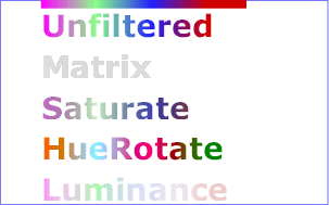
Example feColorMatrix shows examples of the four types of feColorMatrix operations.
<?xml version="1.0"?>
<!DOCTYPE svg PUBLIC "-//W3C//DTD SVG 20010904//EN"
          "http://www.w3.org/TR/2001/REC-SVG-20010904/DTD/svg10.dtd">
<svg width="8cm" height="5cm" viewBox="0 0 800 500"
     xmlns="http://www.w3.org/2000/svg">
  <title>Example feColorMatrix - Examples of feColorMatrix operations</title>
  <desc>Five text strings showing the effects of feColorMatrix:
        an unfiltered text string acting as a reference,
        use of the feColorMatrix matrix option to convert to grayscale,
        use of the feColorMatrix saturate option,
        use of the feColorMatrix hueRotate option,
        and use of the feColorMatrix luminanceToAlpha option.</desc>
  <defs>
    <linearGradient id="MyGradient" gradientUnits="userSpaceOnUse"
            x1="100" y1="0" x2="500" y2="0">
      <stop offset="0" stop-color="#ff00ff" />
      <stop offset=".33" stop-color="#88ff88" />
      <stop offset=".67" stop-color="#2020ff" />
      <stop offset="1" stop-color="#d00000" />
    </linearGradient>
    <filter id="Matrix" filterUnits="objectBoundingBox"
            x="0%" y="0%" width="100%" height="100%">
      <feColorMatrix type="matrix" in="SourceGraphic"
           values=".33 .33 .33 0 0
                   .33 .33 .33 0 0
                   .33 .33 .33 0 0
                   .33 .33 .33 0 0"/>
    </filter>
    <filter id="Saturate40" filterUnits="objectBoundingBox"
            x="0%" y="0%" width="100%" height="100%">
      <feColorMatrix type="saturate" in="SourceGraphic" values="40%"/>
    </filter>
    <filter id="HueRotate90" filterUnits="objectBoundingBox"
            x="0%" y="0%" width="100%" height="100%">
      <feColorMatrix type="hueRotate" in="SourceGraphic" values="90"/>
    </filter>
    <filter id="LuminanceToAlpha" filterUnits="objectBoundingBox"
            x="0%" y="0%" width="100%" height="100%">
      <feColorMatrix type="luminanceToAlpha" in="SourceGraphic" result="a"/>
      <feComposite in="SourceGraphic" in2="a" operator="in" />
    </filter>
  </defs>
  <rect fill="none" stroke="blue"
        x="1" y="1" width="798" height="498"/>
  <g font-family="Verdana" font-size="75"
            font-weight="bold" fill="url(#MyGradient)" >
    <rect x="100" y="0" width="500" height="20" />
    <text x="100" y="90">Unfiltered</text>
    <text x="100" y="190" filter="url(#Matrix)" >Matrix</text>
    <text x="100" y="290" filter="url(#Saturate40)" >Saturate</text>
    <text x="100" y="390" filter="url(#HueRotate90)" >HueRotate</text>
    <text x="100" y="490" filter="url(#LuminanceToAlpha)" >Luminance</text>
  </g>
</svg>
 |
View this example as SVG (SVG-enabled browsers only)
This filter primitive performs component-wise remapping of data as follows:
R' = feFuncR( R )
G' = feFuncG( G )
B' = feFuncB( B )
A' = feFuncA( A )
for every pixel. It allows operations like brightness adjustment, contrast adjustment, color balance or thresholding.
The calculations are performed on non-premultiplied color values. If the input graphics consists of premultiplied color values, those values are automatically converted into non-premultiplied color values for this operation. (Note that the undoing and redoing of the premultiplication can be avoided if feFuncA is the identity transform and all alpha values on the source graphic are set to 1.)
<!ELEMENT feComponentTransfer (feFuncR?,feFuncG?,feFuncB?,feFuncA?) > <!ATTLIST feComponentTransfer %stdAttrs; %PresentationAttributes-FilterPrimitives; %filter_primitive_attributes_with_in; > <!ENTITY % component_transfer_function_attributes "type (identity | table | discrete | linear | gamma) #REQUIRED tableValues CDATA #IMPLIED slope %Number; #IMPLIED intercept %Number; #IMPLIED amplitude %Number; #IMPLIED exponent %Number; #IMPLIED offset %Number; #IMPLIED" > <!ELEMENT feFuncR (animate|set)* > <!ATTLIST feFuncR %stdAttrs; %component_transfer_function_attributes; > <!ELEMENT feFuncG (animate|set)* > <!ATTLIST feFuncG %stdAttrs; %component_transfer_function_attributes; > <!ELEMENT feFuncB (animate|set)* > <!ATTLIST feFuncB %stdAttrs; %component_transfer_function_attributes; > <!ELEMENT feFuncA (animate|set)* > <!ATTLIST feFuncA %stdAttrs; %component_transfer_function_attributes; > |
The attributes below apply to sub-elements 'feFuncR', 'feFuncG', 'feFuncB' and 'feFuncA' define the transfer functions.
Attribute definitions:
Indicates the type of component transfer function. The type of function determines the applicability of the other attributes.
C' = C
For a value C pick a k such that:
k/N <= C < (k+1)/N
The result C' is given by:
C' = vk + (C - k/N)*N * (vk+1 - vk)
For a value C pick a k such that:
k/N <= C < (k+1)/N
The result C' is given by:
C' = vk
Example feComponentTransfer shows examples of the four types of feComponentTransfer operations.
<?xml version="1.0"?>
<!DOCTYPE svg PUBLIC "-//W3C//DTD SVG 20010904//EN"
          "http://www.w3.org/TR/2001/REC-SVG-20010904/DTD/svg10.dtd">
<svg width="8cm" height="4cm" viewBox="0 0 800 400"
     xmlns="http://www.w3.org/2000/svg">
  <title>Example feComponentTransfer - Examples of feComponentTransfer operations</title>
  <desc>Four text strings showing the effects of feComponentTransfer:
        an identity function acting as a reference,
        use of the feComponentTransfer table option,
        use of the feComponentTransfer linear option,
        and use of the feComponentTransfer gamma option.</desc>
  <defs>
    <linearGradient id="MyGradient" gradientUnits="userSpaceOnUse"
            x1="100" y1="0" x2="600" y2="0">
      <stop offset="0" stop-color="#ff0000" />
      <stop offset=".33" stop-color="#00ff00" />
      <stop offset=".67" stop-color="#0000ff" />
      <stop offset="1" stop-color="#000000" />
    </linearGradient>
    <filter id="Identity" filterUnits="objectBoundingBox"
            x="0%" y="0%" width="100%" height="100%">
      <feComponentTransfer>
        <feFuncR type="identity"/>
        <feFuncG type="identity"/>
        <feFuncB type="identity"/>
        <feFuncA type="identity"/>
      </feComponentTransfer>
    </filter>
    <filter id="Table" filterUnits="objectBoundingBox"
            x="0%" y="0%" width="100%" height="100%">
      <feComponentTransfer>
        <feFuncR type="table" tableValues="0 0 1 1"/>
        <feFuncG type="table" tableValues="1 1 0 0"/>
        <feFuncB type="table" tableValues="0 1 1 0"/>
      </feComponentTransfer>
    </filter>
    <filter id="Linear" filterUnits="objectBoundingBox"
            x="0%" y="0%" width="100%" height="100%">
      <feComponentTransfer>
        <feFuncR type="linear" slope=".5" intercept=".25"/>
        <feFuncG type="linear" slope=".5" intercept="0"/>
        <feFuncB type="linear" slope=".5" intercept=".5"/>
      </feComponentTransfer>
    </filter>
    <filter id="Gamma" filterUnits="objectBoundingBox"
            x="0%" y="0%" width="100%" height="100%">
      <feComponentTransfer>
        <feFuncR type="gamma" amplitude="2" exponent="5" offset="0"/>
        <feFuncG type="gamma" amplitude="2" exponent="3" offset="0"/>
        <feFuncB type="gamma" amplitude="2" exponent="1" offset="0"/>
      </feComponentTransfer>
    </filter>
  </defs>
  <rect fill="none" stroke="blue"
        x="1" y="1" width="798" height="398"/>
  <g font-family="Verdana" font-size="75"
            font-weight="bold" fill="url(#MyGradient)" >
    <rect x="100" y="0" width="600" height="20" />
    <text x="100" y="90">Identity</text>
    <text x="100" y="190" filter="url(#Table)" >TableLookup</text>
    <text x="100" y="290" filter="url(#Linear)" >LinearFunc</text>
    <text x="100" y="390" filter="url(#Gamma)" >GammaFunc</text>
  </g>
</svg>
 |
View this example as SVG (SVG-enabled browsers only)
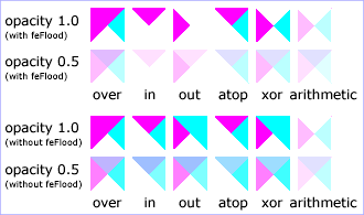
This filter performs the combination of the two input images pixel-wise in image space using one of the Porter-Duff [PORTERDUFF] compositing operations: over, in, atop, out, xor. Additionally, a component-wise arithmetic operation (with the result clamped between [0..1]) can be applied.
The arithmetic operation is useful for combining the output from the 'feDiffuseLighting' and 'feSpecularLighting' filters with texture data. It is also useful for implementing dissolve. If the arithmetic operation is chosen, each result pixel is computed using the following formula:
result = k1*i1*i2 + k2*i1 + k3*i2 + k4
For this filter primitive, the extent of the resulting image might grow as described in the section that describes the filter primitive subregion.
<!ELEMENT feComposite (animate|set)* > <!ATTLIST feComposite %stdAttrs; %PresentationAttributes-FilterPrimitives; %filter_primitive_attributes_with_in; in2 CDATA #REQUIRED operator (over | in | out | atop | xor | arithmetic) "over" k1 %Number; #IMPLIED k2 %Number; #IMPLIED k3 %Number; #IMPLIED k4 %Number; #IMPLIED > |
Attribute definitions:
Example feComposite shows examples of the six types of feComposite operations. It also shows two different techniques to using the BackgroundImage as part of the compositing operation.
The first two rows render bluish triangles into the background. A filter is applied which composites reddish triangles into the bluish triangles using one of the compositing operations. The result from compositing is drawn onto an opaque white temporary surface, and then that result is written to the canvas. (The opaque white temporary surface obliterates the original bluish triangle.)
The last two rows apply the same compositing operations of reddish triangles into bluish triangles. However, the compositing result is directly blended into the canvas (the opaque white temporary surface technique is not used). In some cases, the results are different than when a temporary opaque white surface is used. The original bluish triangle from the background shines through wherever the compositing operation results in completely transparent pixel. In other cases, the result from compositing is blended into the bluish triangle, resulting in a different final color value.
<?xml version="1.0"?>
<!DOCTYPE svg PUBLIC "-//W3C//DTD SVG 20010904//EN"
          "http://www.w3.org/TR/2001/REC-SVG-20010904/DTD/svg10.dtd">
<svg width="330" height="195" viewBox="0 0 1100 650"
     xmlns="http://www.w3.org/2000/svg" xmlns:xlink="http://www.w3.org/1999/xlink">
  <title>Example feComposite - Examples of feComposite operations</title>
  <desc>Four rows of six pairs of overlapping triangles depicting
        the six different feComposite operators under different
        opacity values and different clearing of the background.</desc>
	<defs>
    <desc>Define two sets of six filters for each of the six compositing operators.
          The first set wipes out the background image by flooding with opaque white.
          The second set does not wipe out the background, with the result
          that the background sometimes shines through and is other cases
          is blended into itself (i.e., "double-counting").</desc>
    <filter id="overFlood" filterUnits="objectBoundingBox" x="-5%" y="-5%" width="110%" height="110%">
      <feFlood flood-color="#ffffff" flood-opacity="1" result="flood"/>
      <feComposite in="SourceGraphic" in2="BackgroundImage" operator="over" result="comp"/>
      <feMerge> <feMergeNode in="flood"/> <feMergeNode in="comp"/> </feMerge>
    </filter>
    <filter id="inFlood" filterUnits="objectBoundingBox" x="-5%" y="-5%" width="110%" height="110%">
      <feFlood flood-color="#ffffff" flood-opacity="1" result="flood"/>
      <feComposite in="SourceGraphic" in2="BackgroundImage" operator="in" result="comp"/>
      <feMerge> <feMergeNode in="flood"/> <feMergeNode in="comp"/> </feMerge>
    </filter>
    <filter id="outFlood" filterUnits="objectBoundingBox" x="-5%" y="-5%" width="110%" height="110%">
      <feFlood flood-color="#ffffff" flood-opacity="1" result="flood"/>
      <feComposite in="SourceGraphic" in2="BackgroundImage" operator="out" result="comp"/>
      <feMerge> <feMergeNode in="flood"/> <feMergeNode in="comp"/> </feMerge>
    </filter>
    <filter id="atopFlood" filterUnits="objectBoundingBox" x="-5%" y="-5%" width="110%" height="110%">
      <feFlood flood-color="#ffffff" flood-opacity="1" result="flood"/>
      <feComposite in="SourceGraphic" in2="BackgroundImage" operator="atop" result="comp"/>
      <feMerge> <feMergeNode in="flood"/> <feMergeNode in="comp"/> </feMerge>
    </filter>
    <filter id="xorFlood" filterUnits="objectBoundingBox" x="-5%" y="-5%" width="110%" height="110%">
      <feFlood flood-color="#ffffff" flood-opacity="1" result="flood"/>
      <feComposite in="SourceGraphic" in2="BackgroundImage" operator="xor" result="comp"/>
      <feMerge> <feMergeNode in="flood"/> <feMergeNode in="comp"/> </feMerge>
    </filter>
    <filter id="arithmeticFlood" filterUnits="objectBoundingBox"
            x="-5%" y="-5%" width="110%" height="110%">
      <feFlood flood-color="#ffffff" flood-opacity="1" result="flood"/>
      <feComposite in="SourceGraphic" in2="BackgroundImage" result="comp"
                   operator="arithmetic" k1=".5" k2=".5" k3=".5" k4=".5"/>
      <feMerge> <feMergeNode in="flood"/> <feMergeNode in="comp"/> </feMerge>
    </filter>
    <filter id="overNoFlood" filterUnits="objectBoundingBox" x="-5%" y="-5%" width="110%" height="110%">
      <feComposite in="SourceGraphic" in2="BackgroundImage" operator="over" result="comp"/>
    </filter>
    <filter id="inNoFlood" filterUnits="objectBoundingBox" x="-5%" y="-5%" width="110%" height="110%">
      <feComposite in="SourceGraphic" in2="BackgroundImage" operator="in" result="comp"/>
    </filter>
    <filter id="outNoFlood" filterUnits="objectBoundingBox" x="-5%" y="-5%" width="110%" height="110%">
      <feComposite in="SourceGraphic" in2="BackgroundImage" operator="out" result="comp"/>
    </filter>
    <filter id="atopNoFlood" filterUnits="objectBoundingBox" x="-5%" y="-5%" width="110%" height="110%">
      <feComposite in="SourceGraphic" in2="BackgroundImage" operator="atop" result="comp"/>
    </filter>
    <filter id="xorNoFlood" filterUnits="objectBoundingBox" x="-5%" y="-5%" width="110%" height="110%">
      <feComposite in="SourceGraphic" in2="BackgroundImage" operator="xor" result="comp"/>
    </filter>
    <filter id="arithmeticNoFlood" filterUnits="objectBoundingBox"
            x="-5%" y="-5%" width="110%" height="110%">
      <feComposite in="SourceGraphic" in2="BackgroundImage" result="comp"
                   operator="arithmetic" k1=".5" k2=".5" k3=".5" k4=".5"/>
    </filter>
    <path id="Blue100" d="M 0 0 L 100 0 L 100 100 z" fill="#00ffff" />
    <path id="Red100" d="M 0 0 L 0 100 L 100 0 z" fill="#ff00ff" />
    <path id="Blue50" d="M 0 125 L 100 125 L 100 225 z" fill="#00ffff" fill-opacity=".5" />
    <path id="Red50" d="M 0 125 L 0 225 L 100 125 z" fill="#ff00ff" fill-opacity=".5" />
    <g id="TwoBlueTriangles">
      <use xlink:href="#Blue100"/>
      <use xlink:href="#Blue50"/>
    </g>
    <g id="BlueTriangles">
      <use transform="translate(275,25)" xlink:href="#TwoBlueTriangles"/>
      <use transform="translate(400,25)" xlink:href="#TwoBlueTriangles"/>
      <use transform="translate(525,25)" xlink:href="#TwoBlueTriangles"/>
      <use transform="translate(650,25)" xlink:href="#TwoBlueTriangles"/>
      <use transform="translate(775,25)" xlink:href="#TwoBlueTriangles"/>
      <use transform="translate(900,25)" xlink:href="#TwoBlueTriangles"/>
    </g>
  </defs>

  <rect fill="none" stroke="blue" x="1" y="1" width="1098" height="648"/>
  <g font-family="Verdana" font-size="40" shape-rendering="crispEdges">
    <desc>Render the examples using the filters that draw on top of
          an opaque white surface, thus obliterating the background.</desc>
    <g enable-background="new">
      <text x="15" y="75">opacity 1.0</text>
      <text x="15" y="115" font-size="27">(with feFlood)</text>
      <text x="15" y="200">opacity 0.5</text>
      <text x="15" y="240" font-size="27">(with feFlood)</text>
      <use xlink:href="#BlueTriangles"/>
      <g transform="translate(275,25)">
        <use xlink:href="#Red100" filter="url(#overFlood)" />
        <use xlink:href="#Red50" filter="url(#overFlood)" />
        <text x="5" y="275">over</text>
      </g>
      <g transform="translate(400,25)">
        <use xlink:href="#Red100" filter="url(#inFlood)" />
        <use xlink:href="#Red50" filter="url(#inFlood)" />
        <text x="35" y="275">in</text>
      </g>
      <g transform="translate(525,25)">
        <use xlink:href="#Red100" filter="url(#outFlood)" />
        <use xlink:href="#Red50" filter="url(#outFlood)" />
        <text x="15" y="275">out</text>
      </g>
      <g transform="translate(650,25)">
        <use xlink:href="#Red100" filter="url(#atopFlood)" />
        <use xlink:href="#Red50" filter="url(#atopFlood)" />
        <text x="10" y="275">atop</text>
      </g>
      <g transform="translate(775,25)">
        <use xlink:href="#Red100" filter="url(#xorFlood)" />
        <use xlink:href="#Red50" filter="url(#xorFlood)" />
        <text x="15" y="275">xor</text>
      </g>
      <g transform="translate(900,25)">
        <use xlink:href="#Red100" filter="url(#arithmeticFlood)" />
        <use xlink:href="#Red50" filter="url(#arithmeticFlood)" />
        <text x="-25" y="275">arithmetic</text>
      </g>
    </g>
    <g transform="translate(0,325)" enable-background="new">
    <desc>Render the examples using the filters that do not obliterate
          the background, thus sometimes causing the background to continue
          to appear in some cases, and in other cases the background
          image blends into itself ("double-counting").</desc>
      <text x="15" y="75">opacity 1.0</text>
      <text x="15" y="115" font-size="27">(without feFlood)</text>
      <text x="15" y="200">opacity 0.5</text>
      <text x="15" y="240" font-size="27">(without feFlood)</text>
      <use xlink:href="#BlueTriangles"/>
      <g transform="translate(275,25)">
        <use xlink:href="#Red100" filter="url(#overNoFlood)" />
        <use xlink:href="#Red50" filter="url(#overNoFlood)" />
        <text x="5" y="275">over</text>
      </g>
      <g transform="translate(400,25)">
        <use xlink:href="#Red100" filter="url(#inNoFlood)" />
        <use xlink:href="#Red50" filter="url(#inNoFlood)" />
        <text x="35" y="275">in</text>
      </g>
      <g transform="translate(525,25)">
        <use xlink:href="#Red100" filter="url(#outNoFlood)" />
        <use xlink:href="#Red50" filter="url(#outNoFlood)" />
        <text x="15" y="275">out</text>
      </g>
      <g transform="translate(650,25)">
        <use xlink:href="#Red100" filter="url(#atopNoFlood)" />
        <use xlink:href="#Red50" filter="url(#atopNoFlood)" />
        <text x="10" y="275">atop</text>
      </g>
      <g transform="translate(775,25)">
        <use xlink:href="#Red100" filter="url(#xorNoFlood)" />
        <use xlink:href="#Red50" filter="url(#xorNoFlood)" />
        <text x="15" y="275">xor</text>
      </g>
      <g transform="translate(900,25)">
        <use xlink:href="#Red100" filter="url(#arithmeticNoFlood)" />
        <use xlink:href="#Red50" filter="url(#arithmeticNoFlood)" />
        <text x="-25" y="275">arithmetic</text>
      </g>
    </g>
  </g>
</svg>
 |
View this example as SVG (SVG-enabled browsers only)
feConvolveMatrix applies a matrix convolution filter effect. A convolution combines pixels in the input image with neighboring pixels to produce a resulting image. A wide variety of imaging operations can be achieved through convolutions, including blurring, edge detection, sharpening, embossing and beveling.
A matrix convolution is based on an n-by-m matrix (the convolution kernel) which describes how a given pixel value in the input image is combined with its neighboring pixel values to produce a resulting pixel value. Each result pixel is determined by applying the kernel matrix to the corresponding source pixel and its neighboring pixels. The basic convolution formula which is applied to each color value for a given pixel is:
RESULTX,Y = (
SUMI=0 to [orderY-1] {
SUMJ=0 to [orderX-1] {
SOURCEX-targetX+J, Y-targetY+I * kernelMatrixorderX-J-1, orderY-I-1
}
}
) / divisor + bias
where "orderX" and "orderY" represent the X and Y values for the order attribute, "targetX" represents the value of the targetX attribute, "targetY" represents the value of the targetY attribute, "kernelMatrix" represents the value of the kernelMatrix attribute, "divisor" represents the value of the divisor attribute, and "bias" represents the value of the bias attribute.
Note in the above formulas that the values in the kernel matrix are applied such that the kernel matrix is rotated 180 degrees relative to the source and destination images in order to match convolution theory as described in many computer graphics textbooks.
To illustrate, suppose you have a input image which is 5 pixels by 5 pixels, whose color values for one of the color channels are as follows:
    0  20  40 235 235
  100 120 140 235 235
  200 220 240 235 235
  225 225 255 255 255
  225 225 255 255 255
and you define a 3-by-3 convolution kernel as follows:
  1 2 3
  4 5 6
  7 8 9
Let's focus on the color value at the second row and second column of the image (source pixel value is 120). Assuming the simplest case (where the input image's pixel grid aligns perfectly with the kernel's pixel grid) and assuming default values for attributes divisor, targetX and targetY, then resulting color value will be:
(9*  0 + 8* 20 + 7* 40 +
6*100 + 5*120 + 4*140 +
3*200 + 2*220 + 1*240) / (9+8+7+6+5+4+3+2+1)
Because they operate on pixels, matrix convolutions are inherently resolution-dependent. To make 'feConvolveMatrix produce resolution-independent results, an explicit value should be provided for either the filterRes attribute on the 'filter' element and/or attribute kernelUnitLength.
kernelUnitLength, in combination with the other attributes, defines an implicit pixel grid in the filter effects coordinate system (i.e., the coordinate system established by the primitiveUnits attribute). If the pixel grid established by kernelUnitLength is not scaled to match the pixel grid established by attribute filterRes (implicitly or explicitly), then the input image will be temporarily rescaled to match its pixels with kernelUnitLength. The convolution happens on the resampled image. After applying the convolution, the image is resampled back to the original resolution.
When the image must be resampled to match the coordinate system defined by kernelUnitLength prior to convolution, or resampled to match the device coordinate system after convolution, it is recommended that high quality viewers make use of appropriate interpolation techniques, for example bilinear or bicubic. Depending on the speed of the available interpolents, this choice may be affected by the 'image-rendering' property setting. Note that implementations might choose approaches that minimize or eliminate resampling when not necessary to produce proper results, such as when the document is zoomed out such that kernelUnitLength is considerably smaller than a device pixel.
<!ELEMENT feConvolveMatrix (animate|set)* > <!ATTLIST feConvolveMatrix %stdAttrs; %PresentationAttributes-FilterPrimitives; %filter_primitive_attributes_with_in; order %NumberOptionalNumber; #REQUIRED kernelMatrix CDATA #REQUIRED divisor %Number; #IMPLIED bias %Number; #IMPLIED targetX %Integer; #IMPLIED targetY %Integer; #IMPLIED edgeMode (duplicate|wrap|none) "duplicate" kernelUnitLength %NumberOptionalNumber; #IMPLIED preserveAlpha %Boolean; #IMPLIED > |
Attribute definitions:
Determines how to extend the input image as necessary with color values so that the matrix operations can be applied when the kernel is positioned at or near the edge of the input image.
"duplicate" indicates that the input image is extended along each of its borders as necessary by duplicating the color values at the given edge of the input image.
Original N-by-M image, where m=M-1 and n=N-1:
          11 12 ... 1m 1M
          21 22 ... 2m 2M
          .. .. ... .. ..
          n1 n2 ... nm nM
          N1 N2 ... Nm NM

Extended by two pixels using "duplicate":
  11 11   11 12 ... 1m 1M   1M 1M
  11 11   11 12 ... 1m 1M   1M 1M

  11 11   11 12 ... 1m 1M   1M 1M
  21 21   21 22 ... 2m 2M   2M 2M
  .. ..   .. .. ... .. ..   .. ..
  n1 n1   n1 n2 ... nm nM   nM nM
  N1 N1   N1 N2 ... Nm NM   NM NM

  N1 N1   N1 N2 ... Nm NM   NM NM
  N1 N1   N1 N2 ... Nm NM   NM NM
"wrap" indicates that the input image is extended by taking the color values from the opposite edge of the image.
Extended by two pixels using "wrap":
  nm nM   n1 n2 ... nm nM   n1 n2
  Nm NM   N1 N2 ... Nm NM   N1 N2

  1m 1M   11 12 ... 1m 1M   11 12
  2m 2M   21 22 ... 2m 2M   21 22
  .. ..   .. .. ... .. ..   .. ..
  nm nM   n1 n2 ... nm nM   n1 n2
  Nm NM   N1 N2 ... Nm NM   N1 N2

  1m 1M   11 12 ... 1m 1M   11 12
  2m 2M   21 22 ... 2m 2M   21 22
"none" indicates that the input image is extended with pixel values of zero for R, G, B and A.
Animatable: yes.
This filter primitive lights an image using the alpha channel as a bump map. The resulting image is an RGBA opaque image based on the light color with alpha = 1.0 everywhere. The lighting calculation follows the standard diffuse component of the Phong lighting model. The resulting image depends on the light color, light position and surface geometry of the input bump map.
The light map produced by this filter primitive can be combined with a texture image using the multiply term of the arithmetic 'feComposite' compositing method. Multiple light sources can be simulated by adding several of these light maps together before applying it to the texture image.
The formulas below make use of 3x3 filters. Because they operate on pixels, such filters are inherently resolution-dependent. To make 'feDiffuseLighting' produce resolution-independent results, an explicit value should be provided for either the filterRes attribute on the 'filter' element and/or attribute kernelUnitLength.
kernelUnitLength, in combination with the other attributes, defines an implicit pixel grid in the filter effects coordinate system (i.e., the coordinate system established by the primitiveUnits attribute). If the pixel grid established by kernelUnitLength is not scaled to match the pixel grid established by attribute filterRes (implicitly or explicitly), then the input image will be temporarily rescaled to match its pixels with kernelUnitLength. The 3x3 filters are applied to the resampled image. After applying the filter, the image is resampled back to its original resolution.
When the image must be resampled, it is recommended that high quality viewers make use of appropriate interpolation techniques, for example bilinear or bicubic. Depending on the speed of the available interpolents, this choice may be affected by the 'image-rendering' property setting. Note that implementations might choose approaches that minimize or eliminate resampling when not necessary to produce proper results, such as when the document is zoomed out such that kernelUnitLength is considerably smaller than a device pixel.
For the formulas that follow, the Norm(Ax,Ay,Az) function is defined as:
Norm(Ax,Ay,Az) = sqrt(Ax^2+Ay^2+Az^2)
The resulting RGBA image is computed as follows:
Dr = kd * N.L * Lr
Dg = kd * N.L * Lg
Db = kd * N.L * Lb
Da = 1.0
where
N is a function of x and y and depends on the surface gradient as follows:
The surface described by the input alpha image Ain (x,y) is:
Z (x,y) = surfaceScale * Ain (x,y)
Surface normal is calculated using the Sobel gradient 3x3 filter. Different filter kernels are used depending on whether the given pixel is on the interior or an edge. For each case, the formula is:
Nx (x,y)= - surfaceScale * FACTORx *
(Kx(0,0)*I(x-dx,y-dy) + Kx(1,0)*I(x,y-dy) + Kx(2,0)*I(x+dx,y-dy) +
Kx(0,1)*I(x-dx,y) + Kx(1,1)*I(x,y) + Kx(2,1)*I(x+dx,y) +
Kx(0,2)*I(x-dx,y+dy) + Kx(1,2)*I(x,y+dy) + Kx(2,2)*I(x+dx,y+dy))
Ny (x,y)= - surfaceScale * FACTORy *
(Ky(0,0)*I(x-dx,y-dy) + Ky(1,0)*I(x,y-dy) + Ky(2,0)*I(x+dx,y-dy) +
Ky(0,1)*I(x-dx,y) + Ky(1,1)*I(x,y) + Ky(2,1)*I(x+dx,y) +
Ky(0,2)*I(x-dx,y+dy) + Ky(1,2)*I(x,y+dy) + Ky(2,2)*I(x+dx,y+dy))
Nz (x,y) = 1.0
N = (Nx, Ny, Nz) / Norm((Nx,Ny,Nz))
In these formulas, the dx and dy
values (e.g., I(x-dx,y-dy)),
represent deltas relative to a given (x,y) position for
the purpose of estimating the slope of the surface
at that point. These deltas are determined by the value (explicit or implicit)
of attribute kernelUnitLength.
|
Top/left corner: FACTORx=2/(3*dx) |
Top row: FACTORx=1/(3*dx) |
Top/right corner: FACTORx=2/(3*dx) |
|
Left column: FACTORx=1/(2*dx) |
Interior pixels: FACTORx=1/(4*dx) |
Right column: FACTORx=1/(2*dx) |
|
Bottom/left corner: FACTORx=2/(3*dx) |
Bottom row: FACTORx=1/(3*dx) |
Bottom/right corner: FACTORx=2/(3*dx) |
L, the unit vector from the image sample to the light, is calculated as follows:
For Infinite light sources it is constant:
Lx = cos(azimuth)*cos(elevation)
Ly = sin(azimuth)*cos(elevation)
Lz = sin(elevation)
For Point and spot lights it is a function of position:
Lx = Lightx - x
Ly = Lighty - y
Lz = Lightz - Z(x,y)
L = (Lx, Ly, Lz) / Norm(Lx, Ly, Lz)
where Lightx, Lighty, and Lightz are the input light position.
Lr,Lg,Lb, the light color vector, is a function of position in the spot light case only:
Lr = Lightr*pow((-L.S),specularExponent)
Lg = Lightg*pow((-L.S),specularExponent)
Lb = Lightb*pow((-L.S),specularExponent)
where S is the unit vector pointing from the light to the point (pointsAtX, pointsAtY, pointsAtZ) in the x-y plane:
Sx = pointsAtX - Lightx
Sy = pointsAtY - Lighty
Sz = pointsAtZ - Lightz
S = (Sx, Sy, Sz) / Norm(Sx, Sy, Sz)
If L.S is positive, no light is present. (Lr = Lg = Lb = 0)
<!ELEMENT feDiffuseLighting ((feDistantLight|fePointLight|feSpotLight),(animate|set|animateColor)*) > <!ATTLIST feDiffuseLighting %stdAttrs; class %ClassList; #IMPLIED style %StyleSheet; #IMPLIED %PresentationAttributes-Color; %PresentationAttributes-FilterPrimitives; %PresentationAttributes-LightingEffects; %filter_primitive_attributes_with_in; surfaceScale %Number; #IMPLIED diffuseConstant %Number; #IMPLIED kernelUnitLength %NumberOptionalNumber; #IMPLIED > |
Attribute definitions:
dx and dy, respectively,
in the surface normal calculation formulas. By specifying value(s) for
kernelUnitLength, the kernel becomes defined in a scalable,
abstract coordinate system.
If kernelUnitLength is not specified, the dx and dy
values should represent very small deltas relative to a given (x,y) position, which
might be implemented in some cases as one pixel in the intermediate image offscreen bitmap, which is a pixel-based
coordinate system, and thus potentially not scalable.
For some level of consistency across display media and
user agents, it is necessary that a value be provided for
at least one of filterRes and kernelUnitLength. Discussion of
intermediate images are in the Introduction and in the
description of attribute filterRes. The light source is defined by one of the child elements 'feDistantLight', 'fePointLight' or 'feSpotLight'. The light color is specified by property 'lighting-color'.
This filter primitive uses the pixels values from the image from in2 to spatially displace the image from in. This is the transformation to be performed:
P'(x,y) <- P( x + scale * ((XC(x,y) - .5), y + scale * (YC(x,y) - .5))
where P(x,y) is the input image, in, and P'(x,y) is the destination. XC(x,y) and YC(x,y) are the component values of the designated by the xChannelSelector and yChannelSelector. For example, to use the R component of in2 to control displacement in x and the G component of Image2 to control displacement in y, set xChannelSelector to "R" and yChannelSelector to "G".
The displacement map defines the inverse of the mapping performed.
The calculations using the pixel values from in2 are performed using non-premultiplied color values. If the image from in2 consists of premultiplied color values, those values are automatically converted into non-premultiplied color values before performing this operation.
This filter can have arbitrary non-localized effect on the input which might require substantial buffering in the processing pipeline. However with this formulation, any intermediate buffering needs can be determined by scale which represents the maximum range of displacement in either x or y.
When applying this filter, the source pixel location will often lie between several source pixels. In this case it is recommended that high quality viewers apply an interpolent on the surrounding pixels, for example bilinear or bicubic, rather than simply selecting the nearest source pixel. Depending on the speed of the available interpolents, this choice may be affected by the 'image-rendering' property setting.
The 'color-interpolation-filters' property only applies to the in2 source image and does not apply to the in source image.
<!ELEMENT feDisplacementMap (animate|set)* > <!ATTLIST feDisplacementMap %stdAttrs; %PresentationAttributes-FilterPrimitives; %filter_primitive_attributes_with_in; in2 CDATA #REQUIRED scale %Number; #IMPLIED xChannelSelector (R | G | B | A) "A" yChannelSelector (R | G | B | A) "A" > |
Attribute definitions:
This filter primitive creates a rectangle filled with the color and opacity values from properties 'flood-color' and 'flood-opacity'. The rectangle is as large as the filter primitive subregion established by the x, y, width and height attributes on the 'feFlood' element.
<!ELEMENT feFlood (animate|set|animateColor)* > <!ATTLIST feFlood %stdAttrs; class %ClassList; #IMPLIED style %StyleSheet; #IMPLIED %PresentationAttributes-Color; %PresentationAttributes-feFlood; %PresentationAttributes-FilterPrimitives; %filter_primitive_attributes_with_in; > |
The 'flood-color' property indicates what color to use to flood the current filter primitive subregion. The keyword currentColor and ICC colors can be specified in the same manner as within a <paint> specification for the 'fill' and 'stroke' properties.
| Value: | currentColor | <color> [icc-color(<name>[,<icccolorvalue>]*)] | inherit |
| Initial: | black |
| Applies to: | 'feFlood' elements |
| Inherited: | no |
| Percentages: | N/A |
| Media: | visual |
| Animatable: | yes |
The 'flood-opacity' property defines the opacity value to use across the entire filter primitive subregion.
| Value: | <alphavalue> | inherit |
| Initial: | 1 |
| Applies to: | 'feFlood' elements |
| Inherited: | no |
| Percentages: | N/A |
| Media: | visual |
| Animatable: | yes |
This filter primitive performs a Gaussian blur on the input image.
The Gaussian blur kernel is an approximation of the normalized convolution:
H(x) = exp(-x2/ (2s2)) / sqrt(2* pi*s2)
where 's' is the standard deviation specified by stdDeviation.
The value of stdDeviation can be either one or two numbers. If two numbers are provided, the first number represents a standard deviation value along the x-axis of the current coordinate system and the second value represents a standard deviation in Y. If one number is provided, then that value is used for both X and Y.
Even if only one value is provided for stdDeviation, this can be implemented as a separable convolution.
For larger values of 's' (s >= 2.0), an approximation can be used: Three successive box-blurs build a piece-wise quadratic convolution kernel, which approximates the Gaussian kernel to within roughly 3%.
let d = floor(s * 3*sqrt(2*pi)/4 + 0.5)
... if d is odd, use three box-blurs of size 'd', centered on the output pixel.
... if d is even, two box-blurs of size 'd' (the first one centered on the pixel boundary between the output pixel and the one to the left, the second one centered on the pixel boundary between the output pixel and the one to the right) and one box blur of size 'd+1' centered on the output pixel.
Frequently this operation will take place on alpha-only images, such as that produced by the built-in input, SourceAlpha. The implementation may notice this and optimize the single channel case. If the input has infinite extent and is constant, this operation has no effect. If the input has infinite extent and is a tile, the filter is evaluated with periodic boundary conditions.
<!ELEMENT feGaussianBlur (animate|set)* > <!ATTLIST feGaussianBlur %stdAttrs; %PresentationAttributes-FilterPrimitives; %filter_primitive_attributes_with_in; stdDeviation %NumberOptionalNumber; #IMPLIED > |
Attribute definitions:
The example at the start of this chapter makes use of the feGaussianBlur filter primitive to create a drop shadow effect.
This filter primitive refers to a graphic external to this filter element, which is loaded or rendered into an RGBA raster and becomes the result of the filter primitive.
This filter primitive can refer to an external image or can be a reference to another piece of SVG. It produces an image similar to the built-in image source SourceGraphic except that the graphic comes from an external source.
If the xlink:href references a stand-alone image resource such as a JPEG, PNG or SVG file, then the image resource is rendered according to the behavior of the 'image' element; otherwise, the referenced resource is rendered according to the behavior of the 'use' element. In either case, the current user coordinate system depends on the value of attribute primitiveUnits on the 'filter' element.
When the referenced image must be resampled to match the device coordinate system, it is recommended that high quality viewers make use of appropriate interpolation techniques, for example bilinear or bicubic. Depending on the speed of the available interpolents, this choice may be affected by the 'image-rendering' property setting.
<!ELEMENT feImage (animate|set|animateTransform)* > <!ATTLIST feImage %stdAttrs; %xlinkRefAttrsEmbed; xlink:href %URI; #REQUIRED %langSpaceAttrs; externalResourcesRequired %Boolean; #IMPLIED class %ClassList; #IMPLIED style %StyleSheet; #IMPLIED %PresentationAttributes-All; > |
This filter primitive composites input image layers on top of each other using the over operator with Input1 (corresponding to the first 'feMergeNode' child element) on the bottom and the last specified input, InputN (corresponding to the last 'feMergeNode' child element), on top.
Many effects produce a number of intermediate layers in order to create the final output image. This filter allows us to collapse those into a single image. Although this could be done by using n-1 Composite-filters, it is more convenient to have this common operation available in this form, and offers the implementation some additional flexibility.
Each 'feMerge' element can have any number of 'feMergeNode' subelements, each of which has an in attribute.
The canonical implementation of feMerge is to render the entire effect into one RGBA layer, and then render the resulting layer on the output device. In certain cases (in particular if the output device itself is a continuous tone device), and since merging is associative, it might be a sufficient approximation to evaluate the effect one layer at a time and render each layer individually onto the output device bottom to top.
If the topmost image input is SourceGraphic and this 'feMerge' is the last filter primitive in the filter, the implementation is encouraged to render the layers up to that point, and then render the SourceGraphic directly from its vector description on top.
<!ELEMENT feMerge (feMergeNode)* > <!ATTLIST feMerge %stdAttrs; %PresentationAttributes-FilterPrimitives; %filter_primitive_attributes; > <!ELEMENT feMergeNode (animate|set)* > <!ATTLIST feMergeNode %stdAttrs; in CDATA #IMPLIED > |
The example at the start of this chapter makes use of the feMerge filter primitive to composite two intermediate filter results together.
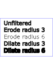
This filter primitive performs "fattening" or "thinning" of artwork. It is particularly useful for fattening or thinning an alpha channel.
The dilation (or erosion) kernel is a rectangle with a width of 2*x-radius and a height of 2*y-radius. In dilation, the output pixel is the individual component-wise maximum of the corresponding R,G,B,A values in the input image's kernel rectangle. In erosion, the output pixel is the individual component-wise minimum of the corresponding R,G,B,A values in the input image's kernel rectangle.
Frequently this operation will take place on alpha-only images, such as that produced by the built-in input, SourceAlpha. In that case, the implementation might want to optimize the single channel case.
If the input has infinite extent and is constant, this operation has no effect. If the input has infinite extent and is a tile, the filter is evaluated with periodic boundary conditions.
Because 'feMorphology' operates on premultipied color values, it will always result in color values less than or equal to the alpha channel.
<!ELEMENT feMorphology (animate|set)* > <!ATTLIST feMorphology %stdAttrs; %PresentationAttributes-FilterPrimitives; %filter_primitive_attributes_with_in; operator (erode | dilate) "erode" radius %NumberOptionalNumber; #IMPLIED > |
Attribute definitions:
Example feMorphology shows examples of the four types of feMorphology operations.
<?xml version="1.0"?>
<!DOCTYPE svg PUBLIC "-//W3C//DTD SVG 20010904//EN"
          "http://www.w3.org/TR/2001/REC-SVG-20010904/DTD/svg10.dtd">
<svg width="5cm" height="7cm" viewBox="0 0 700 500"
     xmlns="http://www.w3.org/2000/svg">
  <title>Example feMorphology - Examples of erode and dilate</title>
  <desc>Five text strings drawn as outlines.
        The first is unfiltered. The second and third use 'erode'.
        The fourth and fifth use 'dilate'.</desc>
  <defs>
    <filter id="Erode3">
      <feMorphology operator="erode" in="SourceGraphic" radius="3" />
    </filter>
    <filter id="Erode6">
      <feMorphology operator="erode" in="SourceGraphic" radius="6" />
    </filter>
    <filter id="Dilate3">
      <feMorphology operator="dilate" in="SourceGraphic" radius="3" />
    </filter>
    <filter id="Dilate6">
      <feMorphology operator="dilate" in="SourceGraphic" radius="6" />
    </filter>
  </defs>
  <rect fill="none" stroke="blue" stroke-width="2"
        x="1" y="1" width="698" height="498"/>
  <g enable-background="new" >
    <g font-family="Verdana" font-size="75"
              fill="none" stroke="black" stroke-width="6" >
      <text x="50" y="90">Unfiltered</text>
      <text x="50" y="180" filter="url(#Erode3)" >Erode radius 3</text>
      <text x="50" y="270" filter="url(#Erode6)" >Erode radius 6</text>
      <text x="50" y="360" filter="url(#Dilate3)" >Dilate radius 3</text>
      <text x="50" y="450" filter="url(#Dilate6)" >Dilate radius 6</text>
    </g>
  </g>
</svg>
 |
View this example as SVG (SVG-enabled browsers only)
This filter primitive offsets the input image relative to its current position in the image space by the specified vector.
This is important for effects like drop shadows.
When applying this filter, the destination location may be offset by a fraction of a pixel in device space. In this case a high quality viewer should make use of appropriate interpolation techniques, for example bilinear or bicubic. This is especially recommended for dynamic viewers where this interpolation provides visually smoother movement of images. For static viewers this is less of a concern. Close attention should be made to the 'image-rendering' property setting to determine the authors intent.
<!ELEMENT feOffset (animate|set)* > <!ATTLIST feOffset %stdAttrs; %PresentationAttributes-FilterPrimitives; %filter_primitive_attributes_with_in; dx %Number; #IMPLIED dy %Number; #IMPLIED > |
Attribute definitions:
The example at the start of this chapter makes use of the feOffset filter primitive to offset the drop shadow from the original source graphic.
This filter primitive lights a source graphic using the alpha channel as a bump map. The resulting image is an RGBA image based on the light color. The lighting calculation follows the standard specular component of the Phong lighting model. The resulting image depends on the light color, light position and surface geometry of the input bump map. The result of the lighting calculation is added. The filter primitive assumes that the viewer is at infinity in the z direction (i.e., the unit vector in the eye direction is (0,0,1) everywhere).
This filter primitive produces an image which contains the specular reflection part of the lighting calculation. Such a map is intended to be combined with a texture using the add term of the arithmetic 'feComposite' method. Multiple light sources can be simulated by adding several of these light maps before applying it to the texture image.
The resulting RGBA image is computed as follows:
Sr = ks * pow(N.H, specularExponent) * Lr
Sg = ks * pow(N.H, specularExponent) * Lg
Sb = ks * pow(N.H, specularExponent) * Lb
Sa = max(Sr, Sg, Sb)
where
See 'feDiffuseLighting' for definition of N and (Lr, Lg, Lb).
The definition of H reflects our assumption of the constant eye vector E = (0,0,1):
H = (L + E) / Norm(L+E)
where L is the light unit vector.
Unlike the 'feDiffuseLighting', the 'feSpecularLighting' filter produces a non-opaque image. This is due to the fact that the specular result (Sr,Sg,Sb,Sa) is meant to be added to the textured image. The alpha channel of the result is the max of the color components, so that where the specular light is zero, no additional coverage is added to the image and a fully white highlight will add opacity.
The 'feDiffuseLighting' and 'feSpecularLighting' filters will often be applied together. An implementation may detect this and calculate both maps in one pass, instead of two.
<!ELEMENT feSpecularLighting ((feDistantLight|fePointLight|feSpotLight),(animate|set|animateColor)*) > <!ATTLIST feSpecularLighting %stdAttrs; class %ClassList; #IMPLIED style %StyleSheet; #IMPLIED %PresentationAttributes-Color; %PresentationAttributes-FilterPrimitives; %PresentationAttributes-LightingEffects; %filter_primitive_attributes_with_in; surfaceScale %Number; #IMPLIED specularConstant %Number; #IMPLIED specularExponent %Number; #IMPLIED kernelUnitLength %NumberOptionalNumber; #IMPLIED > |
Attribute definitions:
The light source is defined by one of the child elements 'feDistantLight', 'fePointLight' or 'feDistantLight'. The light color is specified by property 'lighting-color'.
The example at the start of this chapter makes use of the feSpecularLighting filter primitive to achieve a highly reflective, 3D glowing effect.
This filter primitive fills a target rectangle with a repeated, tiled pattern of an input image. The target rectangle is as large as the filter primitive subregion established by the x, y, width and height attributes on the 'feTile' element.
Typically, the input image has been defined with its own
filter primitive subregion
in order to define a reference tile.
'feTile' replicates the reference tile
in both X and Y to completely fill the target rectangle.
The top/left corner of each given tile is at location (x+i*width,y+j*height),
where (x,y) represents the top/left of the input image's
filter primitive subregion, width and height represent
the width and height of the input image's filter primitive subregion,
and i and j can be any integer value.
In most cases, the input image will have a smaller filter primitive subregion
than the 'feTile' in order to achieve a repeated pattern effect.
Implementers must take appropriate measures in constructing the tiled image to avoid artifacts between tiles, particularly in situations where the user to device transform includes shear and/or rotation. Unless care is taken, interpolation can lead to edge pixels in the tile having opacity values lower or higher than expected due to the interaction of painting adjacent tiles which each have partial overlap with particular pixels.
<!ELEMENT feTile (animate|set)* > <!ATTLIST feTile %stdAttrs; %PresentationAttributes-FilterPrimitives; %filter_primitive_attributes_with_in; > |
This filter primitive creates an image using the Perlin turbulence function. It allows the synthesis of artificial textures like clouds or marble. For a detailed description the of the Perlin turbulence function, see "Texturing and Modeling", Ebert et al, AP Professional, 1994. The resulting image will fill the entire filter primitive subregion for this filter primitive.
It is possible to create bandwidth-limited noise by synthesizing only one octave.
The C code below shows the exact algorithm used for this filter effect.
For fractalSum, you get a turbFunctionResult that is aimed at a range of
-1 to 1 (the actual result might exceed this range in some cases). To convert to a color value, use the
formula colorValue = ((turbFunctionResult * 255) + 255) / 2, then clamp to
the range 0 to 255.
For turbulence, you get a turbFunctionResult that is aimed at a range of
0 to 1 (the actual result might exceed this range in some cases). To convert to a color value, use the
formula colorValue = (turbFunctionResult * 255), then clamp to the range 0
to 255.
The following order is used for applying the pseudo random numbers. An initial seed value is computed based on attribute seed. Then the implementation computes the lattice points for R, then continues getting additional pseudo random numbers relative to the last generated pseudo random number and computes the lattice points for G, and so on for B and A.
The generated color and alpha values are in the color space determined by the value of property 'color-interpolation-filters':
/* Produces results in the range [1, 2**31 - 2].
Algorithm is: r = (a * r) mod m
where a = 16807 and m = 2**31 - 1 = 2147483647
See [Park & Miller], CACM vol. 31 no. 10 p. 1195, Oct. 1988
To test: the algorithm should produce the result 1043618065
as the 10,000th generated number if the original seed is 1.
*/
#define RAND_m 2147483647 /* 2**31 - 1 */
#define RAND_a 16807 /* 7**5; primitive root of m */
#define RAND_q 127773 /* m / a */
#define RAND_r 2836 /* m % a */

long setup_seed(long lSeed)
{
  if (lSeed <= 0) lSeed = -(lSeed % (RAND_m - 1)) + 1;
  if (lSeed > RAND_m - 1) lSeed = RAND_m - 1;
  return lSeed;
}

long random(long lSeed)
{
  long result;
  result = RAND_a * (lSeed % RAND_q) - RAND_r * (lSeed / RAND_q);
  if (result <= 0) result += RAND_m;
  return result;
}

#define BSize 0x100
#define BM 0xff
#define PerlinN 0x1000
#define NP 12 /* 2^PerlinN */
#define NM 0xfff
static uLatticeSelector[BSize + BSize + 2];
static double fGradient[4][BSize + BSize + 2][2];
struct StitchInfo
{
  int nWidth; // How much to subtract to wrap for stitching.
  int nHeight;
  int nWrapX; // Minimum value to wrap.
  int nWrapY;
};

static void init(long lSeed)
{
  double s;
  int i, j, k;
  lSeed = setup_seed(lSeed);
  for(k = 0; k < 4; k++)
  {
    for(i = 0; i < BSize; i++)
    {
      uLatticeSelector[i] = i;
      for (j = 0; j < 2; j++)
        fGradient[k][i][j] = (double)(((lSeed = random(lSeed)) % (BSize + BSize)) - BSize) / BSize;
      s = double(sqrt(fGradient[k][i][0] * fGradient[k][i][0] + fGradient[k][i][1] * fGradient[k][i][1]));
      fGradient[k][i][0] /= s;
      fGradient[k][i][1] /= s;
    }
  }
  while(--i)
  {
    k = uLatticeSelector[i];
    uLatticeSelector[i] = uLatticeSelector[j = (lSeed = random(lSeed)) % BSize];
    uLatticeSelector[j] = k;
  }
  for(i = 0; i < BSize + 2; i++)
  {
    uLatticeSelector[BSize + i] = uLatticeSelector[i];
    for(k = 0; k < 4; k++)
      for(j = 0; j < 2; j++)
        fGradient[k][BSize + i][j] = fGradient[k][i][j];
  }
}

#define s_curve(t) ( t * t * (3. - 2. * t) )
#define lerp(t, a, b) ( a + t * (b - a) )
double noise2(int nColorChannel, double vec[2], StitchInfo *pStitchInfo)
{
  int bx0, bx1, by0, by1, b00, b10, b01, b11;
  double rx0, rx1, ry0, ry1, *q, sx, sy, a, b, t, u, v;
  register i, j;
  t = vec[0] + PerlinN;
  bx0 = (int)t;
  bx1 = bx0+1;
  rx0 = t - (int)t;
  rx1 = rx0 - 1.0f;
  t = vec[1] + PerlinN;
  by0 = (int)t;
  by1 = by0+1;
  ry0 = t - (int)t;
  ry1 = ry0 - 1.0f;

  // If stitching, adjust lattice points accordingly.
  if(pStitchInfo != NULL)
  {
    if(bx0 >= pStitchInfo->nWrapX)
      bx0 -= pStitchInfo->nWidth;
    if(bx1 >= pStitchInfo->nWrapX)
      bx1 -= pStitchInfo->nWidth;
    if(by0 >= pStitchInfo->nWrapY)
      by0 -= pStitchInfo->nHeight;
    if(by1 >= pStitchInfo->nWrapY)
      by1 -= pStitchInfo->nHeight;
  }

  bx0 &= BM;
  bx1 &= BM;
  by0 &= BM;
  by1 &= BM;

  i = uLatticeSelector[bx0];
  j = uLatticeSelector[bx1];
  b00 = uLatticeSelector[i + by0];
  b10 = uLatticeSelector[j + by0];
  b01 = uLatticeSelector[i + by1];
  b11 = uLatticeSelector[j + by1];
  sx = double(s_curve(rx0));
  sy = double(s_curve(ry0));
  q = fGradient[nColorChannel][b00]; u = rx0 * q[0] + ry0 * q[1];
  q = fGradient[nColorChannel][b10]; v = rx1 * q[0] + ry0 * q[1];
  a = lerp(sx, u, v);
  q = fGradient[nColorChannel][b01]; u = rx0 * q[0] + ry1 * q[1];
  q = fGradient[nColorChannel][b11]; v = rx1 * q[0] + ry1 * q[1];
  b = lerp(sx, u, v);
  return lerp(sy, a, b);
}

double turbulence(int nColorChannel, double *point, double fBaseFreqX, double fBaseFreqY,
          int nNumOctaves, bool bFractalSum, bool bDoStitching,
          double fTileX, double fTileY, double fTileWidth, double fTileHeight)
{
  StitchInfo stitch;
  StitchInfo *pStitchInfo = NULL; // Not stitching when NULL.

  // Adjust the base frequencies if necessary for stitching.
  if(bDoStitching)
  {
    // When stitching tiled turbulence, the frequencies must be adjusted
    // so that the tile borders will be continuous.
    if(fBaseFreqX != 0.0)
    {
      double fLoFreq = double(floor(fTileWidth * fBaseFreqX)) / fTileWidth;
      double fHiFreq = double(ceil(fTileWidth * fBaseFreqX)) / fTileWidth;
      if(fBaseFreqX / fLoFreq < fHiFreq / fBaseFreqX)
        fBaseFreqX = fLoFreq;
      else
        fBaseFreqX = fHiFreq;
    }

    if(fBaseFreqY != 0.0)
    {
      double fLoFreq = double(floor(fTileHeight * fBaseFreqY)) / fTileHeight;
      double fHiFreq = double(ceil(fTileHeight * fBaseFreqY)) / fTileHeight;
      if(fBaseFreqY / fLoFreq < fHiFreq / fBaseFreqY)
        fBaseFreqY = fLoFreq;
      else
        fBaseFreqY = fHiFreq;
    }

    // Set up initial stitch values.
    pStitchInfo = &stitch;
    stitch.nWidth = int(fTileWidth * fBaseFreqX + 0.5f);
    stitch.nWrapX = fTileX * fBaseFreqX + PerlinN + stitch.nWidth;
    stitch.nHeight = int(fTileHeight * fBaseFreqY + 0.5f);
    stitch.nWrapY = fTileY * fBaseFreqY + PerlinN + stitch.nHeight;
  }

  double fSum = 0.0f;
  double vec[2];
  vec[0] = point[0] * fBaseFreqX;
  vec[1] = point[1] * fBaseFreqY;
  double ratio = 1;
  for(int nOctave = 0; nOctave < nNumOctaves; nOctave++)
  {
    if(bFractalSum)
      fSum += double(noise2(nColorChannel, vec, pStitchInfo) / ratio);
    else
      fSum += double(fabs(noise2(nColorChannel, vec, pStitchInfo)) / ratio);

    vec[0] *= 2;
    vec[1] *= 2;
    ratio *= 2;

    if(pStitchInfo != NULL)
    {
      // Update stitch values. Subtracting PerlinN before the multiplication and
      // adding it afterward simplifies to subtracting it once.
      stitch.nWidth *= 2;
      stitch.nWrapX = 2 * stitch.nWrapX - PerlinN;
      stitch.nHeight *= 2;
      stitch.nWrapY = 2 * stitch.nWrapY - PerlinN;
    }
  }
  return fSum;
}
<!ELEMENT feTurbulence (animate|set)* > <!ATTLIST feTurbulence %stdAttrs; %PresentationAttributes-FilterPrimitives; %filter_primitive_attributes; baseFrequency %NumberOptionalNumber; #IMPLIED numOctaves %Integer; #IMPLIED seed %Number; #IMPLIED stitchTiles (stitch | noStitch) "noStitch" type (fractalNoise | turbulence) "turbulence" > |
Attribute definitions:
lowFreq=floor(width*frequency)/width
and hiFreq=ceil(width*frequency)/width.
If frequency/lowFreq < hiFreq/frequency then use lowFreq, else use
hiFreq.
While generating turbulence values, generate lattice vectors as normal
for Perlin Noise, except for those lattice points that lie on the right
or bottom edges of the active area (the size of the resulting tile).
In those cases, copy the lattice vector from the opposite edge of the active area.Example feTurbulence shows the effects of various parameter settings for feTurbulence.
<?xml version="1.0"?>
<!DOCTYPE svg PUBLIC "-//W3C//DTD SVG 20010904//EN"
          "http://www.w3.org/TR/2001/REC-SVG-20010904/DTD/svg10.dtd">
<svg width="450px" height="325px" viewBox="0 0 450 325"
     xmlns="http://www.w3.org/2000/svg">
  <title>Example feTurbulence - Examples of feTurbulence operations</title>
  <desc>Six rectangular areas showing the effects of
        various parameter settings for feTurbulence.</desc>
  <g  font-family="Verdana" text-anchor="middle" font-size="10" >
    <defs>
      <filter id="Turb1" filterUnits="objectBoundingBox"
              x="0%" y="0%" width="100%" height="100%">
        <feTurbulence type="turbulence" baseFrequency="0.05" numOctaves="2"/>
      </filter>
      <filter id="Turb2" filterUnits="objectBoundingBox"
              x="0%" y="0%" width="100%" height="100%">
        <feTurbulence type="turbulence" baseFrequency="0.1" numOctaves="2"/>
      </filter>
      <filter id="Turb3" filterUnits="objectBoundingBox"
              x="0%" y="0%" width="100%" height="100%">
        <feTurbulence type="turbulence" baseFrequency="0.05" numOctaves="8"/>
      </filter>
      <filter id="Turb4" filterUnits="objectBoundingBox"
              x="0%" y="0%" width="100%" height="100%">
        <feTurbulence type="fractalNoise" baseFrequency="0.1" numOctaves="4"/>
      </filter>
      <filter id="Turb5" filterUnits="objectBoundingBox"
              x="0%" y="0%" width="100%" height="100%">
        <feTurbulence type="fractalNoise" baseFrequency="0.4" numOctaves="4"/>
      </filter>
      <filter id="Turb6" filterUnits="objectBoundingBox"
              x="0%" y="0%" width="100%" height="100%">
        <feTurbulence type="fractalNoise" baseFrequency="0.1" numOctaves="1"/>
      </filter>
    </defs>

    <rect x="1" y="1" width="448" height="323"
          fill="none" stroke="blue" stroke-width="1"  />

    <rect x="25" y="25" width="100" height="75" filter="url(#Turb1)"  />
    <text x="75" y="117">type=turbulence</text>
    <text x="75" y="129">baseFrequency=0.05</text>
    <text x="75" y="141">numOctaves=2</text>

    <rect x="175" y="25" width="100" height="75" filter="url(#Turb2)"  />
    <text x="225" y="117">type=turbulence</text>
    <text x="225" y="129">baseFrequency=0.1</text>
    <text x="225" y="141">numOctaves=2</text>

    <rect x="325" y="25" width="100" height="75" filter="url(#Turb3)"  />
    <text x="375" y="117">type=turbulence</text>
    <text x="375" y="129">baseFrequency=0.05</text>
    <text x="375" y="141">numOctaves=8</text>

    <rect x="25" y="180" width="100" height="75" filter="url(#Turb4)"  />
    <text x="75" y="272">type=fractalNoise</text>
    <text x="75" y="284">baseFrequency=0.1</text>
    <text x="75" y="296">numOctaves=4</text>

    <rect x="175" y="180" width="100" height="75" filter="url(#Turb5)"  />
    <text x="225" y="272">type=fractalNoise</text>
    <text x="225" y="284">baseFrequency=0.4</text>
    <text x="225" y="296">numOctaves=4</text>

    <rect x="325" y="180" width="100" height="75" filter="url(#Turb6)"  />
    <text x="375" y="272">type=fractalNoise</text>
    <text x="375" y="284">baseFrequency=0.1</text>
    <text x="375" y="296">numOctaves=1</text>
  </g>
</svg>
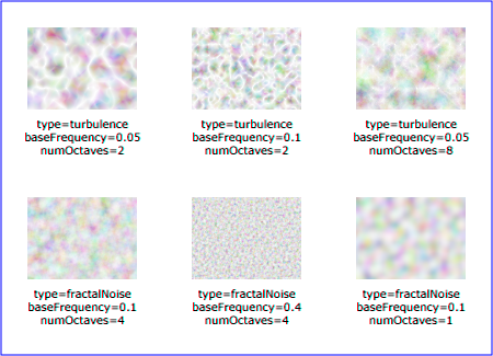 |
View this example as SVG (SVG-enabled browsers only)
The following interfaces are defined below: SVGFilterElement, SVGFilterPrimitiveStandardAttributes, SVGFEBlendElement, SVGFEColorMatrixElement, SVGFEComponentTransferElement, SVGComponentTransferFunctionElement, SVGFEFuncRElement, SVGFEFuncGElement, SVGFEFuncBElement, SVGFEFuncAElement, SVGFECompositeElement, SVGFEConvolveMatrixElement, SVGFEDiffuseLightingElement, SVGFEDistantLightElement, SVGFEPointLightElement, SVGFESpotLightElement, SVGFEDisplacementMapElement, SVGFEFloodElement, SVGFEGaussianBlurElement, SVGFEImageElement, SVGFEMergeElement, SVGFEMergeNodeElement, SVGFEMorphologyElement, SVGFEOffsetElement, SVGFESpecularLightingElement, SVGFETileElement, SVGFETurbulenceElement.
The SVGFilterElement interface corresponds to the 'filter' element.
interface SVGFilterElement :
                SVGElement,
                SVGURIReference,
                SVGLangSpace,
                SVGExternalResourcesRequired,
                SVGStylable,
                SVGUnitTypes {

  readonly attribute SVGAnimatedEnumeration filterUnits;
  readonly attribute SVGAnimatedEnumeration primitiveUnits;
  readonly attribute SVGAnimatedLength      x;
  readonly attribute SVGAnimatedLength      y;
  readonly attribute SVGAnimatedLength      width;
  readonly attribute SVGAnimatedLength      height;
  readonly attribute SVGAnimatedInteger    filterResX;
  readonly attribute SVGAnimatedInteger    filterResY;

  void setFilterRes ( in unsigned long filterResX, in unsigned long filterResY );
};
| in unsigned long filterResX | The X component of attribute filterRes. | |
| in unsigned long filterResY | The Y component of attribute filterRes. |
This interface defines the set of DOM attributes that are common across the filter interfaces.
interface SVGFilterPrimitiveStandardAttributes : SVGStylable {
  readonly attribute SVGAnimatedLength x;
  readonly attribute SVGAnimatedLength y;
  readonly attribute SVGAnimatedLength width;
  readonly attribute SVGAnimatedLength height;
  readonly attribute SVGAnimatedString result;
};
The SVGFEBlendElement interface corresponds to the 'feBlend' element.
interface SVGFEBlendElement :
                SVGElement,
                SVGFilterPrimitiveStandardAttributes {

  // Blend Mode Types
  const unsigned short SVG_FEBLEND_MODE_UNKNOWN  = 0;
  const unsigned short SVG_FEBLEND_MODE_NORMAL   = 1;
  const unsigned short SVG_FEBLEND_MODE_MULTIPLY = 2;
  const unsigned short SVG_FEBLEND_MODE_SCREEN   = 3;
  const unsigned short SVG_FEBLEND_MODE_DARKEN   = 4;
  const unsigned short SVG_FEBLEND_MODE_LIGHTEN  = 5;

  readonly attribute SVGAnimatedString      in1;
  readonly attribute SVGAnimatedString      in2;
  readonly attribute SVGAnimatedEnumeration mode;
};
| SVG_FEBLEND_MODE_UNKNOWN | The type is not one of predefined types. It is invalid to attempt to define a new value of this type or to attempt to switch an existing value to this type. | |
| SVG_FEBLEND_MODE_NORMAL | Corresponds to value normal. | |
| SVG_FEBLEND_MODE_MULTIPLY | Corresponds to value multiply. | |
| SVG_FEBLEND_MODE_SCREEN | Corresponds to value screen. | |
| SVG_FEBLEND_MODE_DARKEN | Corresponds to value darken. | |
| SVG_FEBLEND_MODE_LIGHTEN | Corresponds to value lighten. |
The SVGFEColorMatrixElement interface corresponds to the 'feColorMatrix' element.
interface SVGFEColorMatrixElement :
                SVGElement,
                SVGFilterPrimitiveStandardAttributes {

  // Color Matrix Types
  const unsigned short SVG_FECOLORMATRIX_TYPE_UNKNOWN          = 0;
  const unsigned short SVG_FECOLORMATRIX_TYPE_MATRIX           = 1;
  const unsigned short SVG_FECOLORMATRIX_TYPE_SATURATE         = 2;
  const unsigned short SVG_FECOLORMATRIX_TYPE_HUEROTATE        = 3;
  const unsigned short SVG_FECOLORMATRIX_TYPE_LUMINANCETOALPHA = 4;

  readonly attribute SVGAnimatedString      in1;
  readonly attribute SVGAnimatedEnumeration type;
  readonly attribute SVGAnimatedNumberList  values;
};
| SVG_FECOLORMATRIX_TYPE_UNKNOWN | The type is not one of predefined types. It is invalid to attempt to define a new value of this type or to attempt to switch an existing value to this type. | |
| SVG_FECOLORMATRIX_TYPE_MATRIX | Corresponds to value matrix. | |
| SVG_FECOLORMATRIX_TYPE_SATURATE | Corresponds to value saturate. | |
| SVG_FECOLORMATRIX_TYPE_HUEROTATE | Corresponds to value hueRotate. | |
| SVG_FECOLORMATRIX_TYPE_LUMINANCETOALPHA | Corresponds to value luminanceToAlpha. |
Provides access to the contents of the values attribute.
The SVGFEComponentTransferElement interface corresponds to the 'feComponentTransfer' element.
interface SVGFEComponentTransferElement :
                SVGElement,
                SVGFilterPrimitiveStandardAttributes {

  readonly attribute SVGAnimatedString in1;
};
This interface defines a base interface used by the component transfer function interfaces.
interface SVGComponentTransferFunctionElement : SVGElement {
  // Component Transfer Types
  const unsigned short SVG_FECOMPONENTTRANSFER_TYPE_UNKNOWN  = 0;
  const unsigned short SVG_FECOMPONENTTRANSFER_TYPE_IDENTITY = 1;
  const unsigned short SVG_FECOMPONENTTRANSFER_TYPE_TABLE    = 2;
  const unsigned short SVG_FECOMPONENTTRANSFER_TYPE_DISCRETE    = 3;
  const unsigned short SVG_FECOMPONENTTRANSFER_TYPE_LINEAR   = 4;
  const unsigned short SVG_FECOMPONENTTRANSFER_TYPE_GAMMA    = 5;

  readonly attribute SVGAnimatedEnumeration type;
  readonly attribute SVGAnimatedNumberList  tableValues;
  readonly attribute SVGAnimatedNumber      slope;
  readonly attribute SVGAnimatedNumber      intercept;
  readonly attribute SVGAnimatedNumber      amplitude;
  readonly attribute SVGAnimatedNumber      exponent;
  readonly attribute SVGAnimatedNumber      offset;
};
| SVG_FECOMPONENTTRANSFER_TYPE_UNKNOWN | The type is not one of predefined types. It is invalid to attempt to define a new value of this type or to attempt to switch an existing value to this type. | |
| SVG_FECOMPONENTTRANSFER_TYPE_IDENTITY | Corresponds to value identity. | |
| SVG_FECOMPONENTTRANSFER_TYPE_TABLE | Corresponds to value table. | |
| SVG_FECOMPONENTTRANSFER_TYPE_DISCRETE | Corresponds to value discrete. | |
| SVG_FECOMPONENTTRANSFER_TYPE_LINEAR | Corresponds to value linear. | |
| SVG_FECOMPONENTTRANSFER_TYPE_GAMMA | Corresponds to value gamma. |
The SVGFEFuncRElement interface corresponds to the 'feFuncR' element.
interface SVGFEFuncRElement : SVGComponentTransferFunctionElement {};
The SVGFEFuncGElement interface corresponds to the 'feFuncG' element.
interface SVGFEFuncGElement : SVGComponentTransferFunctionElement {};
The SVGFEFuncBElement interface corresponds to the 'feFuncB' element.
interface SVGFEFuncBElement : SVGComponentTransferFunctionElement {};
The SVGFEFuncAElement interface corresponds to the 'feFuncA' element.
interface SVGFEFuncAElement : SVGComponentTransferFunctionElement {};
The SVGFECompositeElement interface corresponds to the 'feComposite' element.
interface SVGFECompositeElement :
                SVGElement,
                SVGFilterPrimitiveStandardAttributes {

  // Composite Operators
  const unsigned short SVG_FECOMPOSITE_OPERATOR_UNKNOWN    = 0;
  const unsigned short SVG_FECOMPOSITE_OPERATOR_OVER       = 1;
  const unsigned short SVG_FECOMPOSITE_OPERATOR_IN         = 2;
  const unsigned short SVG_FECOMPOSITE_OPERATOR_OUT        = 3;
  const unsigned short SVG_FECOMPOSITE_OPERATOR_ATOP       = 4;
  const unsigned short SVG_FECOMPOSITE_OPERATOR_XOR        = 5;
  const unsigned short SVG_FECOMPOSITE_OPERATOR_ARITHMETIC = 6;

  readonly attribute SVGAnimatedString      in1;
  readonly attribute SVGAnimatedString      in2;
  readonly attribute SVGAnimatedEnumeration operator;
  readonly attribute SVGAnimatedNumber      k1;
  readonly attribute SVGAnimatedNumber      k2;
  readonly attribute SVGAnimatedNumber      k3;
  readonly attribute SVGAnimatedNumber      k4;
};
| SVG_FECOMPOSITE_OPERATOR_UNKNOWN | The type is not one of predefined types. It is invalid to attempt to define a new value of this type or to attempt to switch an existing value to this type. | |
| SVG_FECOMPOSITE_OPERATOR_OVER | Corresponds to value over. | |
| SVG_FECOMPOSITE_OPERATOR_IN | Corresponds to value in. | |
| SVG_FECOMPOSITE_OPERATOR_OUT | Corresponds to value out. | |
| SVG_FECOMPOSITE_OPERATOR_ATOP | Corresponds to value atop. | |
| SVG_FECOMPOSITE_OPERATOR_XOR | Corresponds to value xor. | |
| SVG_FECOMPOSITE_OPERATOR_ARITHMETIC | Corresponds to value arithmetic. |
The SVGFEConvolveMatrixElement interface corresponds to the 'feConvolveMatrix' element.
interface SVGFEConvolveMatrixElement :
                SVGElement,
                SVGFilterPrimitiveStandardAttributes {

  // Edge Mode Values
  const unsigned short SVG_EDGEMODE_UNKNOWN   = 0;
  const unsigned short SVG_EDGEMODE_DUPLICATE = 1;
  const unsigned short SVG_EDGEMODE_WRAP      = 2;
  const unsigned short SVG_EDGEMODE_NONE      = 3;

  readonly attribute SVGAnimatedInteger     orderX;
  readonly attribute SVGAnimatedInteger     orderY;
  readonly attribute SVGAnimatedNumberList  kernelMatrix;
  readonly attribute SVGAnimatedNumber      divisor;
  readonly attribute SVGAnimatedNumber      bias;
  readonly attribute SVGAnimatedInteger     targetX;
  readonly attribute SVGAnimatedInteger     targetY;
  readonly attribute SVGAnimatedEnumeration edgeMode;
  readonly attribute SVGAnimatedLength      kernelUnitLengthX;
  readonly attribute SVGAnimatedLength      kernelUnitLengthY;
  readonly attribute SVGAnimatedBoolean     preserveAlpha;
};
| SVG_EDGEMODE_UNKNOWN | The type is not one of predefined types. It is invalid to attempt to define a new value of this type or to attempt to switch an existing value to this type. | |
| SVG_EDGEMODE_DUPLICATE | Corresponds to value duplicate. | |
| SVG_EDGEMODE_WRAP | Corresponds to value wrap. | |
| SVG_EDGEMODE_NONE | Corresponds to value none. |
The SVGFEDiffuseLightingElement interface corresponds to the 'feDiffuseLighting' element.
interface SVGFEDiffuseLightingElement :
                SVGElement,
                SVGFilterPrimitiveStandardAttributes {

  readonly attribute SVGAnimatedString in1;
  readonly attribute SVGAnimatedNumber surfaceScale;
  readonly attribute SVGAnimatedNumber diffuseConstant;
};
The SVGFEDistantLightElement interface corresponds to the 'feDistantLight' element.
interface SVGFEDistantLightElement : SVGElement {
  readonly attribute SVGAnimatedNumber azimuth;
  readonly attribute SVGAnimatedNumber elevation;
};
The SVGFEPointLightElement interface corresponds to the 'fePointLight' element.
interface SVGFEPointLightElement : SVGElement {
  readonly attribute SVGAnimatedNumber x;
  readonly attribute SVGAnimatedNumber y;
  readonly attribute SVGAnimatedNumber z;
};
The SVGFESpotLightElement interface corresponds to the 'feSpotLight' element.
interface SVGFESpotLightElement : SVGElement {
  readonly attribute SVGAnimatedNumber x;
  readonly attribute SVGAnimatedNumber y;
  readonly attribute SVGAnimatedNumber z;
  readonly attribute SVGAnimatedNumber pointsAtX;
  readonly attribute SVGAnimatedNumber pointsAtY;
  readonly attribute SVGAnimatedNumber pointsAtZ;
  readonly attribute SVGAnimatedNumber specularExponent;
  readonly attribute SVGAnimatedNumber limitingConeAngle;
};
The SVGFEDisplacementMapElement interface corresponds to the 'feDisplacementMap' element.
interface SVGFEDisplacementMapElement :
                SVGElement,
                SVGFilterPrimitiveStandardAttributes {

  // Channel Selectors
  const unsigned short SVG_CHANNEL_UNKNOWN = 0;
  const unsigned short SVG_CHANNEL_R       = 1;
  const unsigned short SVG_CHANNEL_G       = 2;
  const unsigned short SVG_CHANNEL_B       = 3;
  const unsigned short SVG_CHANNEL_A       = 4;

  readonly attribute SVGAnimatedString      in1;
  readonly attribute SVGAnimatedString      in2;
  readonly attribute SVGAnimatedNumber      scale;
  readonly attribute SVGAnimatedEnumeration xChannelSelector;
  readonly attribute SVGAnimatedEnumeration yChannelSelector;
};
| SVG_CHANNEL_UNKNOWN | The type is not one of predefined types. It is invalid to attempt to define a new value of this type or to attempt to switch an existing value to this type. | |
| SVG_CHANNEL_R | Corresponds to value R. | |
| SVG_CHANNEL_G | Corresponds to value G. | |
| SVG_CHANNEL_B | Corresponds to value B. | |
| SVG_CHANNEL_A | Corresponds to value A. |
The SVGFEFloodElement interface corresponds to the 'feFlood' element.
interface SVGFEFloodElement :
                SVGElement,
                SVGFilterPrimitiveStandardAttributes {

  readonly attribute SVGAnimatedString      in1;
};
The SVGFEGaussianBlurElement interface corresponds to the 'feGaussianBlur' element.
interface SVGFEGaussianBlurElement :
                SVGElement,
                SVGFilterPrimitiveStandardAttributes {

  readonly attribute SVGAnimatedString in1;
  readonly attribute SVGAnimatedNumber stdDeviationX;
  readonly attribute SVGAnimatedNumber stdDeviationY;

  void setStdDeviation ( in float stdDeviationX, in float stdDeviationY );
};
| in float stdDeviationX | The X component of attribute stdDeviation. | |
| in float stdDeviationY | The Y component of attribute stdDeviation. |
The SVGFEImageElement interface corresponds to the 'feImage' element.
interface SVGFEImageElement :
                SVGElement,
                SVGURIReference,
                SVGLangSpace,
                SVGExternalResourcesRequired,
                SVGFilterPrimitiveStandardAttributes {};
The SVGFEMergeElement interface corresponds to the 'feMerge' element.
interface SVGFEMergeElement :
                SVGElement,
                SVGFilterPrimitiveStandardAttributes {};
The SVGFEMergeNodeElement interface corresponds to the 'feMergeNode' element.
interface SVGFEMergeNodeElement : SVGElement {
  readonly attribute SVGAnimatedString in1;
};
The SVGFEMorphologyElement interface corresponds to the 'feMorphology' element.
interface SVGFEMorphologyElement :
                SVGElement,
                SVGFilterPrimitiveStandardAttributes {

  // Morphology Operators
  const unsigned short SVG_MORPHOLOGY_OPERATOR_UNKNOWN = 0;
  const unsigned short SVG_MORPHOLOGY_OPERATOR_ERODE   = 1;
  const unsigned short SVG_MORPHOLOGY_OPERATOR_DILATE  = 2;

  readonly attribute SVGAnimatedString      in1;
  readonly attribute SVGAnimatedEnumeration operator;
  readonly attribute SVGAnimatedLength      radiusX;
  readonly attribute SVGAnimatedLength      radiusY;
};
| SVG_MORPHOLOGY_OPERATOR_UNKNOWN | The type is not one of predefined types. It is invalid to attempt to define a new value of this type or to attempt to switch an existing value to this type. | |
| SVG_MORPHOLOGY_OPERATOR_ERODE | Corresponds to value erode. | |
| SVG_MORPHOLOGY_OPERATOR_DILATE | Corresponds to value dilate. |
The SVGFEOffsetElement interface corresponds to the 'feOffset' element.
interface SVGFEOffsetElement :
                SVGElement,
                SVGFilterPrimitiveStandardAttributes {

  readonly attribute SVGAnimatedString in1;
  readonly attribute SVGAnimatedNumber dx;
  readonly attribute SVGAnimatedNumber dy;
};
The SVGFESpecularLightingElement interface corresponds to the 'feSpecularLighting' element.
interface SVGFESpecularLightingElement :
                SVGElement,
                SVGFilterPrimitiveStandardAttributes {

  readonly attribute SVGAnimatedString in1;
  readonly attribute SVGAnimatedNumber surfaceScale;
  readonly attribute SVGAnimatedNumber specularConstant;
  readonly attribute SVGAnimatedNumber specularExponent;
};
The SVGFETileElement interface corresponds to the 'feTile' element.
interface SVGFETileElement :
                SVGElement,
                SVGFilterPrimitiveStandardAttributes {

  readonly attribute SVGAnimatedString in1;
};
The SVGFETurbulenceElement interface corresponds to the 'feTurbulence' element.
interface SVGFETurbulenceElement :
                SVGElement,
                SVGFilterPrimitiveStandardAttributes {

  // Turbulence Types
  const unsigned short SVG_TURBULENCE_TYPE_UNKNOWN      = 0;
  const unsigned short SVG_TURBULENCE_TYPE_FRACTALNOISE = 1;
  const unsigned short SVG_TURBULENCE_TYPE_TURBULENCE   = 2;
  // Stitch Options
  const unsigned short SVG_STITCHTYPE_UNKNOWN  = 0;
  const unsigned short SVG_STITCHTYPE_STITCH   = 1;
  const unsigned short SVG_STITCHTYPE_NOSTITCH = 2;

  readonly attribute SVGAnimatedNumber      baseFrequencyX;
  readonly attribute SVGAnimatedNumber      baseFrequencyY;
  readonly attribute SVGAnimatedInteger     numOctaves;
  readonly attribute SVGAnimatedNumber      seed;
  readonly attribute SVGAnimatedEnumeration stitchTiles;
  readonly attribute SVGAnimatedEnumeration type;
};
| SVG_TURBULENCE_TYPE_UNKNOWN | The type is not one of predefined types. It is invalid to attempt to define a new value of this type or to attempt to switch an existing value to this type. | |
| SVG_TURBULENCE_TYPE_FRACTALNOISE | Corresponds to value fractalNoise. | |
| SVG_TURBULENCE_TYPE_TURBULENCE | Corresponds to value turbulence. |
| SVG_STITCHTYPE_UNKNOWN | The type is not one of predefined types. It is invalid to attempt to define a new value of this type or to attempt to switch an existing value to this type. | |
| SVG_STITCHTYPE_STITCH | Corresponds to value stitch. | |
| SVG_STITCHTYPE_NOSTITCH | Corresponds to value noStitch. |

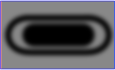
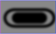
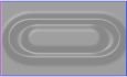
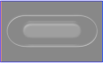

