By publishing this document, W3C acknowledges that International
Business Machines, Inc. and Novell, Inc.
have made a formal submission to W3C for discussion. Publication of
this document by W3C indicates no endorsement of its content by
W3C, nor that W3C has, is, or will be allocating any resources to
the issues addressed by it. This document is not the product of a
chartered W3C group, but is published as potential input to the
W3C Process. Publication of
acknowledged Member Submissions at the W3C site is one of the
benefits of W3C
Membership. Please consult the requirements associated with
Member Submissions of
section 3.3 of the W3C Patent Policy. Please consult the
complete list of acknowledged W3C Member
Submissions.
The purpose of this specification is to define
the schema of an XML document describing the characteristics of an
installable unit (IU) of software that are relevant for its
deployment, configuration and maintenance. The XML schema is
referred to as the Installable Unit Deployment Descriptor or
IUDD schema.
IUDDs are intended to describe the aggregation
of installable units at all levels of the software stack, including
middleware products aggregated together into a platform; and user
solutions composed of application-level artifacts which run on such
a platform. The XML schema is flexible enough to support the
definition of atomic units of software (Smallest Installable
Units) as well as complex solutions.
The IUDD provides a unique
identification of each installable unit and it supports a
declarative specification of dependencies that each IU may have on
its hosting environment and on other units of software. This
information can be leveraged by common tools and services to reduce
the human interactions required for
This document does not define how the
contents of a root installable unit, including the descriptor, are
physically packaged together. This is defined in a separate
specification [IUPACK].
This document is intended as a technical
specification for people who require an in-depth understanding of
the installable unit deployment descriptor. This includes
developers of the IUDDs themselves, and developers of the
associated tooling and applications for constructing and deploying
IUDDs. This document is not intended as an introduction to the
concepts of solution deployment or as a tutorial for
developers.
The key words “MUST,”
“MUST NOT,” “REQUIRED,”
“SHALL,” “SHALL NOT,” “SHOULD,”
“SHOULD NOT,” “RECOMMENDED,”
“MAY,” and “OPTIONAL” are to be interpreted
as described in [RFC2119].
The installable unit deployment descriptor
(IUDD) is a means for describing the components of a solution, and
for providing instructions on how to deploy and configure that
solution. The IUDD is a reusable asset that can be deployed onto
many different physical topologies, and can be aggregated into
larger solutions. It establishes knowledge of the relationships and
dependencies between components of the solution, which can then be
used for its lifecycle management.
An SIU is limited in scope to describing a
unit of software that is targeted to and is entirely contained by
the single hosting environment where it is deployed. Analogously, a
CU defines the configuration applying to a single resource (target)
in the topology.
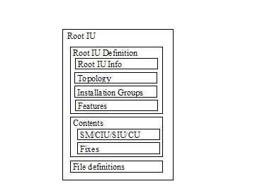
Figure 1 shows the structure of the IUDD,
effectively the structure of the associated root IU definition.
Information in the IUDD is independent from
the package format, which is covered by a separate specification
[IUPACK]. The latter describes how to construct a package including
the IUDD and all the other files that may need to be accessed in
order to deploy the root IU.
The independence of the IUDD and packaging
specifications allows an IU to be composed flexibly, and to make
packaging decisions independently from the logical definition of
the installable units.
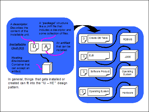
Figure 2 shows the fundamental
architectural pattern for solution deployment. An installable
unit is the fundamental building block or component from which
products or solutions are composed. An installable unit package
consists of a descriptor, which describes the content of the
installable unit, and one or more artifacts that are to be
installed. The installable unit is installed into a hosting
environment, which is a container that can accept the artifacts
in the installable unit.
This architectural pattern is reusable
at all levels of the software stack, from the operating system,
through the middleware, up to application artifacts such as EJBs
and database tables.
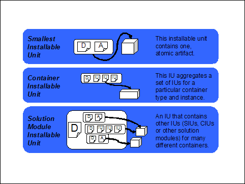
Figure 3 describes the installable unit
types introduced in section 11.
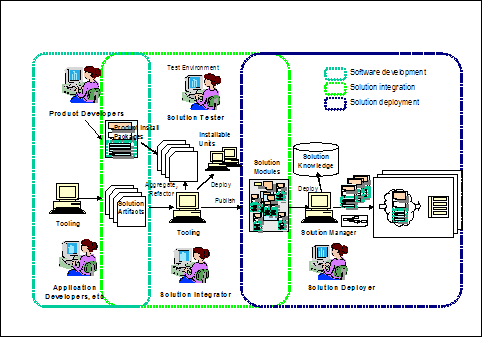
The overall process for developing and
deploying a solution is illustrated in Figure 4. A solution is
developed by application developers and/or product developers; it
is then packaged as one or more root installable units, at which
point the requirements on the target topology is defined; and
distributed to deployers. The deployer makes installation-specific
decisions about how the installable unit is to be configured, and
the solution depoyment tooling assists in mapping the logical
target topology defined in the IUDD onto the physical topology. The
solution components (installable units) are then distributed and
installed.
The IUDD schema is implemented by eight
schema files. Types defined in each file are identified by a
specific prefix, as indicated in the following:
Artifacts associated to an installable
unit (see Section 3.1 above) also have an associated XML
descriptor. However, artifacts are referenced from within the IUDD
through an identifier of the corresponding file. Since they are not
defined inline within the IUDD, the XML schema for artifacts
are independent from the IUDD schema files. See Section 14 and
Section 15 for a proposed artifact schema.
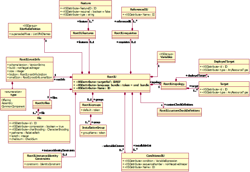
The class diagram in the following page
illustrates the composition relationships of the RootIU class with other types
defined in the IUDD schema. The following sections provide an
overview of types represented in the diagram. This provides an
introduction to the detailed XML schema definitions of those types
that are described later in this document.
Variables is an aggregate containing
the variable definitions associated with the root IU.
ConditionedIU is the generic type
describing any contained IU defined within the root IU. Two
compositions of this type are defined by a root IU: one is for the
base content (installableUnit) while the other is for features
(selectableContent).
IUs that can appear in an IU aggregate
have an associated condition. The condition is a boolean
variable expression. When the condition is false, the IU is not
selected for install. IUs defined within the aggregate may
have siblings. A sequence number may be associated to the IU to
specify the order in which the IU should be processed with respect
to its siblings.
The rootInfo element defines
characteristics of the root IU instance, such as the schema version
on which it is based and the size of all files associated to
artifacts defined in this root IU.
A root IU may define zero or more
features. Either each feature represents a top-level IUs defined
inline within the RootIU or it is a reference to a feature
in a referenced, separately packaged IU. In both cases, the IU
referred to by the feature definition MUST be defined within the
root IU selectable content composite.
The root IU may define zero or more
groups of features (installation groups). Each group represents a
combination of installable units that could be chosen for a given
configuration or role, e.g. minimal versus typical; administrator
versus developer versus client.
The root IU topology is a composite of
one or more target definitions. A target can be a hosting
environment onto which one or more IUs are to be deployed, or it
can be a generic resource that is needed for the proper functioning
of the solution. Ordinary targets pre-exist the solution
deployment. Deployed targets are defined in the topology to
represent resources that are created by instantiating an
installable unit.
The customCheckDefinitions element
includes definitions of check artifacts. Each artifact is a
descriptor of actions that need to be performed on a target to
establish if the latter satisfies some given requirements. Some of
the actions defined in a check artifact may specify the execution
of custom code. Multiple checks defined in different IUs may need
to reuse the same custom check artifact. For this reason, the
identification of check artifacts is factored out in the root
IU.
In addition to IUs that are part of the
aggregate, the root IU may define requisite IUs, i.e. bundled
packaged IUs, which may be installed on a target to satisfy a
software requirement.
The files element of the root IU is a
composite of File definitions. Each File definition includes a file
identifier. Any element within a root IU that is associated to a
physical file declares that association by means of a reference to
the corresponding file identifier. Examples of elements associated
to a physical file are Referenced IUs and bundled requisite IUs.
Actions specified within install artifacts (see Section 9.4)
may also contain references to physical files that need to be
bundled with the root IU. These files need to be defined in the
files element.
The following data-flow diagram provides a
model for the process involved in a software change. This model is
provided as an illustrative example and alternative processes MAY
be supported by an implementation of an install runtime. The
process is a sequence of five logical activities: Environment
Checks, Input, Dependency Check, Change and Register. These
activities interact with the target hosting environment, and the
installable unit database. The hosting environment (e.g. a
configured operating system image) is the actual destination of the
software being installed. The installable unit database is the
repository holding information about the installable unit
configuration for a set of hosting environments within a given
scope (for example those on a single machine, or those within a
complete administrative domain). The user provides input, in this
process, either interactively or via a response file, and that
input drives the activity of a software installer program.
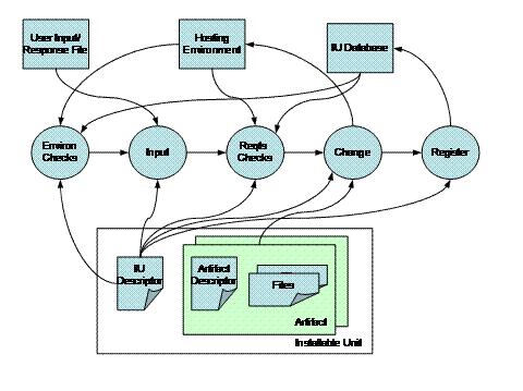
Figure 5: Model of the
software change management process
The rectangles at the bottom of Figure 5
represent entities defined in this specification:
The rectangle on the left represents the IU
descriptor, conforming to the IUDD XML descriptor defined by this specification.
The rectangles on the right side represent
artifacts associated to an SIU or to a CU. An SIU or CU may
define multiple artifacts, each one associated to a different type
of change (operation). Each artifact includes one artifact
descriptor defining actions – such as the ones for
creating or removing files on an operating system environment.
Action definitions in the artifact descriptor are interpreted on
the IU’s hosting environment to implement the change, and may
reference files that need to be available when the actions are
performed.
The following list provides a description of
the five logical activities illustrated in Figure
5:
- Environment
Checks.
Gather information about the current environment (e.g. the presence
of installed software on the target system). This activity
generally executes before entering into the interactive stage of an
attended installation or other change management operation, because
the information may be used by an installer to determine the
additional input that the user should provide during an interactive
install. The environment checks should not be affected by user
input: any variable contained in the specification of a check, if
any, should have a well-defined initial value.
- Input.
Obtain replacement values for parameters defined in a package,
either through interactive user input or from a response
file.
- Requirements
Checks.
Ensure that all requirements stated in the IU descriptor for a
given type of change are satisfied before starting the
change.
- Change.
Perform the requested change operation on the installable unit,
such as Create, Configure or Delete. The full list of change
management operations, and the corresponding states of the
installable unit, are described in section 4.2.
- Register.
Persist information about the installable unit. For a Create
operation, this information may include the identity of the newly
created IU instance, its target, its relationships to other
installable units, and the values of variables used in its
installation.
Software deployment has been
traditionally designed and implemented as a process by which a
software package (artifact) is installed on the running operating
system image on one or more physical computers. In general,
deployment of a software component (e.g. a database client) on one
target needs to be coordinated with deployment of a different
software component (e.g. a database server) onto another
target.
“Hosting Environment” is a
term used to denote the target of a software component with
specific characteristics. Therefore, the term “OS hosting
environment” is used to denote the hosting environment of
traditional software products that are installed on an operating
system, while the term “J2EE hosting environment” is
used to denote a J2EE application server hosting J2EE
applications. Other hosting environment types may be defined,
such as RDBMS databases, messaging systems, and other
middle-ware.
The following state diagram applies to
an instance of any installable unit (SIU or aggregate). During its
life-cycle an IU instance makes state transitions as a consequence
of Change Management (CM) operations being applied to it. A CM
operation MAY require an artifact specifying the actions to be
executed on the hosting environment.
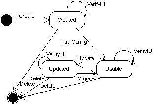
Figure 6: State diagram of an installable unit instance.
Error states that result from errors
encountered when performing any of the indicated operations are not
covered in this specification, and are not shown in the above
diagram.
The following sections 4.2.1 to 4.2.10
describe the operations that create an IU instance, apply updates
and configuration to that instance and delete the instance when it
is no longer needed. The descriptions focus on the meaning of the
operation for an SIU. Applying updates to an IU aggregate is
discussed in Section 11. Ordering of install, applying to both
Create and Update, is defined in Section 12.
The Create operation creates a new
instance of an SIU. The Install artifact associated to the SIU, see
Section 9.4, defines the actions to be executed on the hosting
environment to instantiate the SIU.
The newly created IU instance
transitions directly to the Usable state if no InitialConfig
artifact is specified and there are no sibling configuration units
defined in the same aggregate. Otherwise, the instance enters the
Created state and an InitialConfig operation is needed to bring the
instance to the Usable state.
On some hosting environments, the
operation MAY be used to overwrite an existing instance of the SIU.
The end result SHOULD be the same that would be obtained by
performing the Create operation after applying the Delete operation
to the existing instance.
An SIU may define a new base, an IU
update or a temporary fix. An update can be full, in which case it
is possible to use if for a fresh install; or incremental, in which
case it must be applied to an existing instance. The Create
operation can only be performed for an SIU defining a new base or a
full update. An SIU defining a temporary fix or an incremental
update can only be applied to an existing instance using the Update
operation.
The Update operation updates an
existing instance. The SIU defining an update or temporary
fix contains a declaration of the version range of a base IU
instance onto which it can be applied (update base). The
Install artifact associated to the SIU, see Section 9.4,
defines the actions to be executed on the hosting environment
to update the base instance.
After the update, the version of the
updated instance is changed to reflect the version specified by the
SIU update.
The updated IU instance transitions
directly to the Usable state if no Migrate artifact is specified
and there are no sibling configuration units defined in the same
aggregate. Otherwise, the instance enters the Updated state and the
Migrate operation is needed to bring the instance to the Usable
state.
The update may be applied in undo-able
mode. In this case, any resources (e.g. files) associated to
the instance being updated that are being replaced or modified need
to be saved, in order to support the roll-back of the update.
SIU updates and fixes may supersede
fixes that are already applied to the instance being updated.
The InitialConfig operation applies the
initial configuration to an instance of the installable unit that
is in the Created state, causing the transition to the Usable
state. The operation can only be performed for an SIU defining a
new base or a full update. The operation CANNOT be performed for an
SIU defining a temporary fix or an incremental update.
The InitConfig artifact associated with
the SIU, see Section 9.4, defines actions to be executed on the
hosting environment to make a created instance usable. This
artifact implements the non repeatable part of the initial
configuration.
Sibling configuration units MAY be
defined in the same IU aggregate to implement the repeatable
part of the initial configuration. These configuration units are
applied at the end of the InitialConfig operation, after the
InitConfig artifacts have been processed for all SIUs in the whole
root IU. See Section 4.3.
The Migrate operation applies
configuration to an installable unit instance that is in the
Updated state, causing the transition to the Usable state.
The operation can only be performed for an SIU defining an update
(full or incremental). The operation CANNOT be performed for a
fix.
The Migrate artifact associated with
the SIU, see Section 9.4, defines actions to be executed on the
hosting environment to make an updated instance usable. Actions in
the artifact set the configuration by using existing installable
unit instance data: the actions may implement the migration
of configuration data used in the previous version within the
instance being superseded. The Migrate artifact implements the
non repeatable part of the configuration process.
Sibling configuration units MAY be
defined in the same IU aggregate to capture the repeatable
part of the configuration process. These configuration units are
applied at the end of the Migrate operation, after the Migrate
artifacts have been processed for all SIUs in the whole root IU.
See Section 4.3.
The
Configure operation applies artifacts associated with configuration
units, see Section 10.2, which modify the configuration of a resource (topology
target). The operation can be used to re-configure an installable
unit instance. The operation can be re-applied multiple times to
change the configuration of resources.
The
Configure operation SHOULD be supported with two execution modes:
full and delta.
In
full mode, the operation applies all CUs defined in the base
IU, all updates and all of the fixes to the latest
level.
In
delta mode, the operation can be applied to process either
the set of CUs associated to the latest update level or the
CUs associated to one of the fixes that were applied to the latest
level.
When a full IU is applied as an update to an existing
instance, all CUs associated to aggregates of the base that are not
obsoleted are replaced, see Section 11.1.
The Verify IU operation performs
integrity checking of an installable unit instance with respect to
its current state (Created, Updated, Usable). The final state is
the same as the initial state unless the integrity checks fail, in
which case the unit is put in an error state.
A VerifyInstall artifact MAY be
associated to an SIU, see Section 9.4. If specified, the artifact
defines actions to be executed on the hosting environment to
perform integrity checking of the SIU instance. Some integrity
checking MAY be possible on some hosting environments without
specifying an artifact.
The VerifyConfig operation uses the
VerifyConfig artifact, see Section 10.2, to verify the
configuration of a manageable resource.
Some implementations MAY support the
repair operation to perform the repair of an installable unit
instance that failed a previous verification (VerifyIU). The
installable unit instance remains in the error state if there are
parts whose state was found in error for which a repair capability
is not implemented. The Repair operation has no associated
artifact.
The delete operation deletes an
existing IU instance from the hosting environment.
The Uninstall artifact associated with
the SIU, see Section 9.4, defines the actions to be executed on the
hosting environment to remove resources (e.g. files) created as
part of the instance.
Some hosting environments MAY support
using the install artifact for both the Create and the Delete
operation. In that case, the install artifact is processed by the
Delete operation to identify resources created during install that
need to be removed.
The IU instance may have gone through
multiple updates during its lifecycle. The semantic of the Delete
operation is that all resources created as part of the IU initial
creation and subsequent updates SHOULD be removed, unless they
already existed when the instance was first created (or updated) in
which case they SHOULD NOT be removed.
Undo support is OPTIONAL. Each hosting
environment that can be the target of IU lifecycle operations
specifies which operations, if any, can be performed in undoable
mode. The number of levels of the Undo stack are also
specified by the hosting environment. The release of backup
resources MAY be controlled by the explicit invocation of a Commit
operation. A hosting environment MAY implement an automatic Commit
(e.g. because it does not implement more that a single undoable
operation for the same IU instance).
The semantic of the Undo operation is
explained below, by contrast to the Delete operation.
The result of applying Undo to an
operation is to revert the IU instance to a previous state. For
example, applying the Undo after an Update will revert the IU
instance to its state prior to the update, while Delete would
remove the instance. The Undo applied to a new IU instance after
Create would produce the same effect of the Delete operation if the
Create did not cause any pre-existing resources (e.g. shared files
or registry entry) to be modified. While if the Create did modify
or remove some pre-existing resources, these SHOULD be restored by
Undo while Delete would leave the modified resources in their
current state.
In some cases, restoring the previous
state of a shared resource may not be desirable, namely when the
resource has been subject to further modifications after the backup
copy was created. Also, artifacts may contain actions that
cannot be executed in undoable mode. The conditions that MAY limit
Undo support on a given hosting environment are specified by each
implementation. In particular, actions that can be defined in the
install artifacts MAY support the specification of the desired
behavior when the action should be undone.
InitialConfig and Migrate artifacts
SHOULD only cover the non-repeatable part of an IU instance
configuration so that they are NOT normally re-applied.
An implementation MAY support
re-applying the InitialConfig and Migrate
artifacts on an IU instance that is already in the Usable state.
This MAY be done in an attempt to restore a configuration baseline
in case of a malfunction, although this MAY generally cause loss of
data.
Configuration units can be included at
any aggregate IU level within the root IU to define the
repeatable part of the configuration process. CUs are used
to configure resources created by installing the IU and other
resources on which the IU is dependent for being usable.
Resources created by installing an IU
may be configured by CUs targeted to the same hosting environment
where the IU was deployed, or by CUs targeted to resources that
were created by the IU install process (see deployed targets
in section 5.6.4).
When Configuration Units (CU) are
defined in an aggregate IU, that IU cannot be considered Usable
before the associated configuration have been applied. However, it
SHOULD be possible to apply all configuration units at the end of
the Create or Update process, when all the InitConfig and Migrate
artifacts have been processed.
See Section 12.5.1 for a motivation of
the above rule in a scenario where multiple chained dependencies
need to be installed during an Update.
Configuration units are applied the
first time during the InitialConfig operation. In this case,
configuration units SHOULD be applied after all InitConfig
artifacts for all SIUs in the whole root IU have been processed,
without requiring the explicit invocation of a separate Configure
operation to apply the configuration units.
Configuration units can be successively
processed multiple times by invoking the Configure operation to
change (or to re-apply) the current configuration.
Consistently, configuration units are
applied during the Migrate operation. These configuration units
SHOULD be applied after all Migrate artifacts, without requiring
the explicit invocation of a separate Configure operation.
Only the new CUs introduced by the
update or fix are applied during the Migrate process.
The Create operation leaves an aggregate
IU instance directly in the Usable state if the IU descriptor
specifies no Configuration Unit for that IU and SIUs under the
aggregate specify no InitConfig artifacts. Similarly, the Update
operation leaves the IU instance in the Usable state if no CUs are
defined for the aggregate and SIUs under the aggregate specify no
Migrate artifacts.
The Installable Unit Deployment Descriptor
(IUDD) is the XML instance document defining a root IU. The IUDD
defines a single instance of the iudd:rootIU element.
A number of attributes must be specified for
the root element iudd:rootIU in order to make it possible to locate
the schema files. The following XML fragment illustrates these
attributes for a simple root IU whose content is targeted
exclusively at the operating system hosting environment:
<?xml version="1.0"
encoding="UTF-8"?>
<iudd:rootIU
xmlns:iudd="http://www.ibm.com/namespaces/autonomic/solutioninstall/IUDD"
xmlns:sig="http://www.ibm.com/namespaces/autonomic/solutioninstall/Signatures"
xmlns:OSRT="http://www.ibm.com/namespaces/autonomic/OS_RT"
xmlns:xsi="http://www.w3.org/2001/XMLSchema-instance"
xsi:schemaLocation="http://www.ibm.com/namespaces/autonomic/solutioninstall/IUDD
iudd.xsd "
IUName="MyRootIU"
targetRef="MyTargetOperatingSystem">
The name prefix (xmlns:prefix) and
schema location (xsi:schemaLocation) are already specified in the
main schema file for all the referenced schema files except
signatures.xsd and do not need to be specified in the instance
document. The prefix and schema location attributes for
signatures.xsd need to be specified in the instance document, if
the latter includes signatures information.
OSRT is the prefix for the namespace
xmlns:OSRT defining operating system resource types. Other
namespaces are defined in the resourceTypes.xsd schema file. One or
more of these namespaces may need to be added if the topology
includes target resources of the corresponding type.
Schema diagrams are included in the following
sections to support the description of elements defined in a schema
type. These diagrams only show XML schema elements; they do
not include a graphical representation of XML schema
attributes. The latter are described in the text. The
following graphical conventions are used in these diagrams:
- A solid line border indicates a
required element (minOccurs=”1”)
- A dotted line border indicates an
optional element (minOccurs=”0”)
- Multiple rectangles beneath an
element’s name indicate that there may be multiple
occurrences. In that case, there is a label showing the
multiplicity.
- A small square with an inner “+”
symbol at the right end of a rectangle indicates that the
corresponding element is an instance of a complex type (not
expanded).
- A connector with horizontally aligned dots
indicates a sequence content model.
- A switch connector with vertically
aligned dots indicates a choice content model.
The identity element is required
for any installable unit. The element is an instance of
base:IUIdentity, which is illustrated by the following diagram.
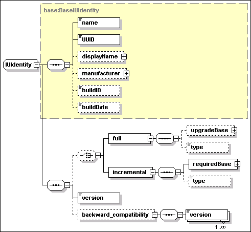
·
UUID
[type=base:UUID]
UUID is a REQUIRED element. A unique identifier for the IU type is
provided by the union of the UUID and version values.
The UUID type is defined to be compatible with existing standards
dictating the generation and string representation of universal
identifiers. The schema required representation of the UUID is by a
hexBinary XML type of length=16-octets (32 chars). Two categories
of generation algorithms have been considered, which both generate
a 16-byte binary UUID. The first category includes the ISO
compliant algorithms based on the use of IEEE 802 identifiers (MAC
address) for the “space” part, e.g. the DCE-RPC UUID
generator. The second category includes algorithms that make no use
of the MAC address.
Note: the hyphenated string version of the UUID specified by the
ISO standard cannot be used as a value of the base:UUID type. The
value must be obtained as the 16-octects hexadecimal representation
of the binary value (no hyphenation).
·
name
[type=token]
This is a REQUIRED element: both name and
UUID MUST be specified. The value is an internal, not
language sensitive name of the software component represented by
the IU. A name is needed for the following non exclusive
uses:
·
Some
implementations of a hosting environment
MAY NOT support UUIDs. However, since both name and UUID are always
available it is not necessary to use multiple IU definitions to
deploy the same IU on different hosting environments.
·
The IU
MAY be installed on a system and be registered in a legacy registry
of installed software by some printable name. This element could
specify the same printable name in the IU XML descriptor, thus
making it possible to identify an instance found in the legacy
registry as an instance of the same IU.
·
A
system providing life-cycle management of installable unit
descriptors, e.g. an IUDD library system, needs to provide means by
which an installable unit can be referred to by a user-friendly
name. As an example: when creating a new version of an existing
installable unit, a developer may need to retrieve the UUID of the
base version. The base application can be retrieved by searching
the library system with the user-friendly name.
·
One
may need to search for different products that have different UUID
yet are all members of a product family. For example, assuming
“MyProduct” version 10 does not declare backward
compatibility with “MyProduct” version 3 the two MAY
have different UUID values (see 5.1.1 below) . A management
application may need to locate all instances of
“MyProduct”, regardless of version. This can be
achieved by a name search if the name of both versions contains a
common sub-string.
·
displayName
[type=base:DisplayElement]
This OPTIONAL element
associates text labels and a description with the corresponding IU.
See Section 17 for a general description of display elements and
their localization.
·
manufacturer
[type=base:DisplayElement]
This OPTIONAL element
specifies the name and description of the IU manufacturer. See
Section 17 for a general description of display elements and their
localization.
·
buildID
[type=token]
This OPTIONAL element is provided to allow
a correlation to a build identifier used in a vendor-specific build
process.
·
buildDate
[type=dateTime]
This OPTIONAL element contains the
build date for the installable unit.
·
version
[type=vsn:VersionString]
This element defines the
IU version. The version value is a string composed of up to four
parts, according to a Version.Release.Modification.Level (V.R.M.L)
scheme. The first and second parts are required
(Version.Release). XML types used in this specifications for
version data are defined in Appendix H.
·
backward_compatibility
[anonymous type – sequence of
vsn:VersionString]
This element defines a sequence of
version elements, each one for a previous version of the same
component, that the current one declares to be backward compatible
with. These previous versions relate to the same UUID: it is not
possible to specify backwards compatibility to a different UUID.
Backwards compatibility implies that any dependency on version
“X” of component “B” stated by a component
“A” CAN be satisfied by a version “Y” of
component “B” that exists in the system if version
“Y” is declared to be backward compatible with version
“X”.
At least the first two parts of the version MUST be specified in
each of these elements. When some of the trailing version parts in
the value of one of these elements are omitted, the IU being
defined is assumed to be backward compatible with any possible
version matching the parts which are specified.
·
full
[anonymous type]
The presence of this element indicates
that the IU can be used for creating a new instance. The OPTIONAL
specification of a upgrade base indicates that it can be used also
as an update to an existing IU instance. See Section 11.
·
incremental
[anonymous type]
The presence of this element indicates
that the IU can only be used as an update to an existing IU
instance. See Section 11.
A new version of an existing
installable unit that maintains compatibility to a previous version
and that is eligible to satisfy dependencies originally stated for
that previous version MUST have the same UUID. In that case, the
backward_compatibility element of the IU identity is used to
formally declare the backward compatibility with one or more
previous versions.
An installable unit that does not
retain full backward compatibility with a previous version, MUST
still retain the same UUID of a previous level if it can install as
a full or incremental update on top of that level.
A new UUID SHOULD be created when the
component is first created or in case the component is broken apart
and pieces used to reconstruct something different.
A new UUID MAY be also created for a
new version which breaks backward compatibility with and cannot be
installed as an upgrade to the previous version.
The following XML fragment illustrates
the elements of IU identity.
<identity>
<name>Human readable name, possibly used in a
native registry</name>
<UUID>12345678901234567890123456789012</UUID>
<displayName>
<defaultLineText key="ST_01">Line text about
package</defaultLineText>
<defaultText key="LT_01"> Paragraph text about
package</defaultText>
</displayName>
<manufacturer>
<defaultLineText key="ST_02">ACME
Software</defaultLineText>
<defaultText key="LT_02">The true ACME
Software</defaultText>
</manufacturer>
<buildID>1234XYZ</buildID>
<buildDate>2001-12-31T12:00:00</buildDate>
<version>1.1</version>
<backward_compatibility>
<version>1.0</version>
</backward_compatibility>
</identity>
A temporary fix is an installable unit
that is not part of the normal sequence of released versions,
although it has a definition similar to that of an ordinary IU. In
particular, the identity of a fix is defined by the
base:FixIdentity type, illustrated by the following diagram. This
type and base:IUIdentity are both derived types of
base:BaseIUIdentity. Therefore, a fix repeats the definition of the
following elements described in the previous section (the name and
UUID elements identify the installable unit to which the fix is
intended to be applied)
·
name
·
UUID
·
displayName
·
manufacturer
·
buildID
·
buildDate
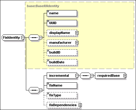
Additional elements of the fix identity
are described below.
·
incremental/requiredBase
[type=base:RequiredBase]
This is a REQUIRED element
specifying the range of versions (minVersion and maxVersion
elements, both instances of vsn:VersionString) to which this fix
can be applied.
·
fixName [type=NCName]
This is a REQUIRED element
specifying the fix name. This name MUST be unique among all fixes
that apply to installable units with the specified UUID.
·
fixType [anonymous type]
This is an OPTIONAL
element, used to categorize the fix. See Section 9.2.
·
fixDependencies [anonymous type]
This is an
OPTIONAL element, used to express dependencies (pre-requisites,
co-requisites and ex-requisites) among fixes that could be applied
to the same IU instance. This element can only be specified for an
IU deployed to a single target (SIU or CIU). See Section 9.2.
A root installable unit describes a
complete “unit of manufacture”, as shipped by the
installable unit developer. There is exactly one root IU in an
installable unit descriptor.
A root installable unit is a derived
type of iudd:AggregatedInstallableUnit, which in turn is a derived
type of siu:InstallableUnit. The relationships between these two
types are illustrated in the following diagram.
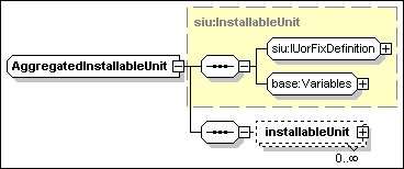
The
base type – siu:InstallableUnit – includes a definition
of the IU via the group siu:IUorFixDefinition – this can
select different contents depending on whether this is an ordinary
IU of a temporary fix – and the group base:Variables. A key
element in the first group is the IU identity whose elements are
described in sections 5.1 and 5.2. Other elements of an IU
definition are covered in Section 9 (Software Smallest Installable
Unit). Variables are covered in section 8 (Variables, Expressions
and Conditions).
The AggregatedInstallableUnit type
defines the base content of the root IU, as a set of
installableUnit elements. Each element is an instance of
type iudd:ConditionedIU, described in Section 6, and may
represent any of the following:
·
An inline IU aggregate, i.e. a Solution Module (SM) or
Container Installable Unit (CIU), respectively described in
Sections 6.1 and 6.4.
·
An inline leaf node, i.e. a Smallest Installable Unit (SIU)
or a Configuration Unit (CU), respectively described in Sections 9
and 10.
·
A bundled referenced IU, described in Section 6.2.
·
A federated IU, described in Section 6.3.
The other top-level elements of the
RootIU type are illustrated in the following diagram.
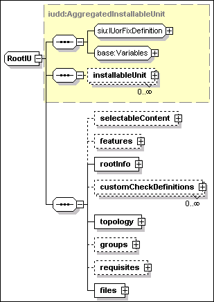
A root installable unit has the
following attributes:
·
IUName [type=ID]
A REQUIRED IUName, which uniquely identifies the IU within the
scope of the descriptor. The value MUST be unique within the
descriptor.
·
targetRef [type=IDREF]
An OPTIONAL targetRef
attribute which if specified MUST refer to one of the targets
defined in the topology. When specified, this attribute implies
that all installable units defined within this root IU MUST be
deployed onto the same target. Consistently with this declaration,
all the installable units that are part of the the root IU MUST
specify the same target.
·
language_bundle [type=token]
An OPTIONAL
attribute which has a default value of “iudd_bundle”.
This is used for the localization of display elements. See Section
17.
A root installable unit has the
following elements:
·
selectableContent [anonymous type]
This element
defines the selectable content of the root IU as a set of
installableUnit elements. These are instances of
iudd:ConditionedIU. The inclusion of installable units defined as
part of the base content is determined by the associated
condition. The inclusion of installable units defined by this
element is also dependent on the selection of features. See Section
5.4.
·
features [anonymous type]
The set of features that may be selected. See Section 5.4.
·
rootInfo [anonymous type]
The rootInfo element, which describes the product or offering
contained in the root IU. See Section 5.5.
·
customCheckDefinitions [anonymous type]
The set of custom checks that is used within the root IU and its
embedded (inline) installable units. Custom checks use artifacts
that can be executed on a target (e.g. an operating system) to
check dependencies that are not defined in this schema. See Section
7.3.8.
·
topology [anonymous type]
The target topology onto which the installable unit is to be
deployed. The target topology consists of a set of target
definitions, covering both targets that must be there before the
root IU can be installed, and targets that may be installed as part
of the install of the root IU. See Section 5.6.
·
groups [anonymous type]
The installation groups that the product or offering supports, and
the default installation group that should be selected if no other
selection is made. An installation group defines a set of features
that should be installed together. See Section 5.4.
·
requisites [anonymous type]
The bundled requisite IUs that are shipped with the root IU. These
are referenced IUs that may be used to satisfy unmet dependencies.
See Section 5.7.
·
files [anonymous type]
The set of files that comprise the root IU. These files are given a
file ID by which they can be referenced within the root IU and are
subject to integrity checks. Each file ID MUST be unique within the
root IU. See Section 5.8.
Features provide the means for external
(e.g. user) selection of the installable units within the root IU.
This is in contrast to conditions, which filter what is installed
based on environmental properties.
Installation groups provide a means of
specifying recommended selections of features, for example tailored
to a particular use, user role or resource constraints. An example
of a set of installation groups might be “Custom”,
“Typical” and “Full”. An installation group
specifies which features the user is able to select from, and which
features are selected by default. Optionally, a default
installation group can be specified.
Features may be specified as the target
of dependency checks. They are identified by a feature name that is
unique within the root IU.
The diagram above illustrates how
features are used. The root IU contains IUs, which are partitioned
into base content (always installed) and those IUs that are
selectable via features. Features contain subfeatures and/or
selectable content. The selectable content can be shared between
multiple features, but subfeatures are not shared. The features
must select the top-level of the content: they cannot arbitrarily
select subtrees.
Referenced IUs also contain features,
and the aggregating IU needs to specify what features within these
referenced IUs should be selected. There are two mechanisms for
doing this. First, the referenced IU definition may specify an
installation group and may also specify explicit selections within
the referenced IU. This will establish the features in the
referenced IU that are to be installed when that referenced IU is
selected. Second, individual features may federate features within
a referenced IU. This will cause the selection of that feature if
it is not already selected. Further, it will associate the
lifecycle of the referenced feature with the feature federating it,
so that if the federating feature is uninstalled and the referenced
feature is no longer used, it may also be uninstalled.
The
selection of features is controlled as follows:
·
As previously identified, what
the user can select and the default selections are set via
installation groups.
·
Some features are identified as
“required”. These features are always selected if their
parent is selected (a top-level required feature is always
selected).
·
Features may identify the
following selection constraints on other features:
o
Select if selected
o
Deselect if selected
o
Select if deselected
o
Deselect if
deselected
·
Referenced features may express
a set of “ifreq” relationships to other features. The
referenced feature is only selected if at least one of its
“ifreqs” is satisfied. If an “ifreq” is
subsequently installed, any features previously selected but not
installed because of the “ifreq” should now be
installed.
The
following illustrates how features and installation groups may be
used, e.g. during an interactive install.
If
the root IU defines installation groups, the user is presented with
the set of installation groups to choose from. If a default
installation group is specified, this indicates the initial
selection that should be presented. If no installation group is
defined, the user may select from any of the features.
Each
defined installation group indicates the set of default feature
selections, and indicates whether the user can change the
selection.
Within an install group, a feature’s selection can be
specified as “not changeable”. This means that the
selection state of the feature is determined entirely by internal
selection rules, and not by user selection. In this case a user
should not be allowed to change the feature’s selection
state.
The
user selects a single install group, and then makes selections from
the offered features.
When
the user had made their selections, the install program will
determine which IUs are to be installed. This will consist of the
base content, plus all IUs that are federated by the selected
features, plus the IUs that are selected in referenced IUs through
the referenced IU definition (see below) or through feature
references. These IUs are then filtered based on any conditions:
only IUs with no condition or a condition that evaluates to true
will be installed.
The
features to be selected in referenced IUs are determined as
follows:
·
An explicit install group can
be specified. If so, this install group specifies the default
selections.
·
If no explicit install group is
specified, the default install group specifies the default
selections.
·
If no explicit or default
install group is specified, no features are selected for the
referenced IU (unless referenced feature definitions are specified
in the root IU, see below).
·
Further explicit feature
selections can be specified in the referenced IU definition. These
are in addition to the selections in the install group. They are
not subject to any constraints specified in the install
group.
Features selected by feature references are then selected
in addition to the selections specified in the referenced IU
definition.
Feature selection is illustrated in the example in Section
C.
Install group and features selections determine the set of
IU that are being installed, but not the order in which these are
installed, which is determined by the IU hierarchy, sequence
numbers and intra-IU dependencies.
Install group selections and feature selection rules are
provided for use by install programs and their implementation is
OPTIONAL. It is the responsibility of those components to determine
the appropriate behavior if the constraints are violated (e.g.
ignore, warn, error).
A feature definition includes the
following attributes:
·
featureID [type=ID]
This REQUIRED attribute
provides a unique identifier to reference the feature
definition within the root IU. The value MUST be unique within the
descriptor.
·
required [type=boolean]
If this OPTIONAL
attribute is true, then the feature is always selected if it is
either a top-level feature, or if its parent feature is
selected.
·
type [type=iudd:FeatureType]
The type of this
OPTIONAL attribute is defined as a union of the XML type NCName and
iudd:StandardFeatureType. Therefore, a user defined feature type
can be specified as an NCName value. “Documentation”,
“Language” and “Samples” are the standard
enumerated values defined in iudd:StandardFeatureType.
A feature definition includes the
elements illustrated in
the following diagram.
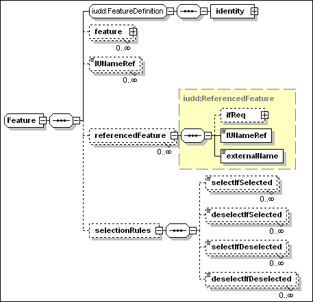
·
identity [anonymous type]
This is an instance of
a type containing the following elements
o
name [type=token]
This is a name by which the feature can be registered, and by which
it is possible to reference the feature from an external
descriptor. The value MUST be unique among features defined within
the same root IU.
o
displayName [type=base:DisplayElement]
This OPTIONAL element may be used to associate a language sensitive
name and description to the feature. See Section 17.
·
feature [type=iudd:Feature]
Zero or more feature
elements can be specified, each one describing a child feature. The
parent-child relationship between two features implies that
children SHOULD NOT be selected when their parent is
selected.
·
IUNameRef [type=IDREF]
Zero or more IUNameRef
elements, each one selecting a top-level IU defined as part of the
root IU selectable content.
·
referencedFeature
[type=iudd:ReferencedFeature]
Zero or more
referencedFeature elements, each one referencing a feature within a
referenced IU. See Section 5.4.2.
·
selectionRules [type=anonymous]
Zero or more
selection rules. Each selection
rule identifies the feature name of a different feature within the
root IU, which is the subject of the rule. The possible rules
are:
o
SelectIfSelected
[type=IDREF]
The specified feature is selected if this feature is
selected.
o
DeselectIfSelected [type=IDREF]
The specified feature is deselected if this feature is
selected.
o
SelectIfDeselected [type=IDREF]
The specified feature is selected if this feature is
deselected.
o
DeselectIfDeselected [type=IDREF]
The specified feature is deselected if this feature is
deselected.
A referenced feature is illustrated in
the diagram below:
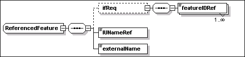
A “referenced feature”
defines a selection of a feature in a referenced IU or in a
federated IU. A referenced feature has the following elements:
·
IUNameRef [type=IDREF]
This REQUIRED element is
the identifier of the referenced or federated IU that the feature
is in. See Section 6.2 for a definition of referenced IUs,
and Section 6.3 for a definition of federated IUs.
·
externalName [type=token]
The value of this
REQUIRED element MUST match the name of the feature, within the
referenced IU descriptor, that needs to be selected. When the
feature is associated to a federated IU, any IU check in the
federated IU definition MUST identify an IU that has a feature with
the specified name.
·
ifReq [type=anonymous]
This OPTIONAL element can be used to specify one or more
featureIDRef elements. These are references of the IDREF type to
features defined within the same root IU of the feature being
defined. The selection of any of the specified features in the root
IU causes the selection of the feature in the referenced IU. See
Appendix C for an example.
A referenced feature can only
refer to a contained referenced IU or a federated IU that is
part of the base or of the selectable content. A referenced feature
CANNOT refer to a requisite IU.
The following rules apply to feature
scope and override.
·
Features are defined in the root IU. The featureID must be unique
within the descriptor.
·
Referenced IUs have a separate namespace for features. The only
interaction is via the specification of the selection of a feature
within a referenced IU or referenced feature.
An installation group is defined by the
iudd:InstallationGroup type. A group defines a set of features that
should be installed if the group is selected.
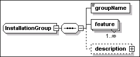
A group definition includes the elements illustrated in the above diagram.
·
groupName [type=token]
This REQUIRED element is the name of the group. The value MUST be
unique within the descriptor.
·
feature [anonymous type]
A list of the feature selections that are to be made as part of the
installation group. A feature selection element consists of the
following attributes:
o
featureIDRef [type=IDREF]
This must be a valid reference to a feature within the root IU.
o
selection [type=iudd:Selection]
This is an enumerated type whose possible values are
“selected” and “not_selected”. This
specifies whether the feature is to be selected or not selected by
default. The default value is “selected”.
o
selectionChangeable [type=boolean]
This element provides an indication of whether the selection is
externally changeable (e.g. by the user or automated install
program). If this indication is “false”, then the
feature’s selection is only changed in response to internal
selection rules. The default value is “true”.
·
description [type=base:DisplayElement]
This is an OPTIONAL human-readable description. See Section 17.
A feature may be a member of multiple
groups, or of no groups.
Groups cannot contain other groups.
The use of installation groups is
illustrated in the example in Appendix C.
The following rules apply to
installation group scope.
·
Groups are defined in the root IU. The value of the groupName
element must be unique within the descriptor.
·
Each referenced IU has a separate namespace for installation
groups. The only interaction is via the specification of the
selection of an install group within a referenced IU.
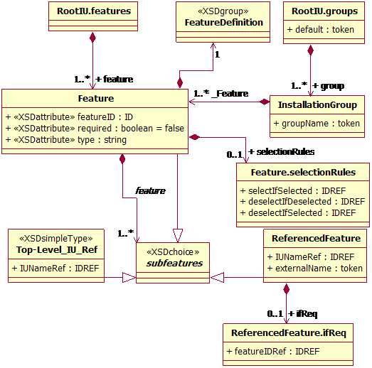
The following UML class diagram
illustrates features and installation groups.
The information included by the rootInfo
element are illustrated in the following diagram.
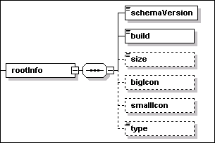
The rootInfo element is a container for
the following elements
·
schemaVersion [type=vsn:VersionString]
This REQUIRED element identifies the version of the schema being
used.
·
build [type=nonNegativeInteger]
This REQUIRED element is the root IU build number. This identifies
the version of the descriptor separately from the version of
installable units that the descriptor contains. A newer (better)
descriptor may be the result of replacing the implementation of a
custom check (external command), or of identifying a previously
unrecognized dependency, or of relaxing a previous dependency
because testing has now validated a wider range of valid
environments. The IU developer is responsible for the decision as
to whether the changes should affect the versioning of an
installable unit.
·
size [type=integer]
This OPTIONAL element defines the size of the root IU, in
Kilo-bytes (1K=1024). The value indicates the amount of disk space
required to store the whole root IU including all descriptors,
files and referenced IUs, in an unpackaged form.
·
bigIcon [anonymous type]
This OPTIONAL element has a REQUIRED attribute – fileIdRef
– of IDREF type. This is a reference to a GIF file containing
a 32x32 icon associated with the root IU.
·
smallIcon [anonymous type]
This OPTIONAL element has a REQUIRED attribute – fileIdRef
– of IDREF type. This is a reference to a GIF file containing
a 16x16 icon associated with the root IU.
·
type [type=NCName]
This OPTIONAL element can be used to categorize the root IU. One
among the following enumerated values can be specified for this
element, to support a componentization strategy:
o
Offering
o
Assembly
o
CommonComponent
5.6
Target Topology
The topology definition consists of a
set of one or more targets and an OPTIONAL set of
deployed targets. Both types define some manageable resource
that play a role in the solution being deployed. In particular,
deployed targets define resources that are created as a result of
deploying the solution.
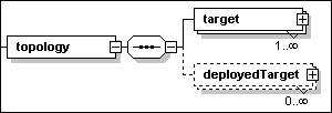
Targets are described in Section 5.6.1.
Deployed targets are described in Section 5.6.4.
A target defines a manageable resource
that plays a role in the solution. A target definition MAY be
referenced within installable units because
·
it represents the installable unit’s hosting environment,
or
·
it is the target of a property query associated to a variable
definition, or
·
it is the target on which a check must be performed, or
·
it is one end of a binary relationship that must exist between two
resources.
The target element is an instance of
the iudd:Target type, illustrated in the following diagram.
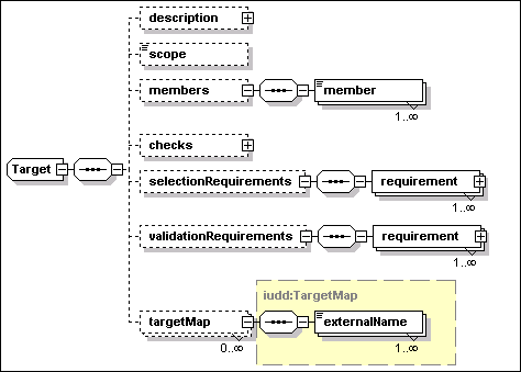
A target definition is used to identify
one or more instances of a given resource type based on
scope, selection requirements and validation
requirements. A target definition has the following
attributes:
·
id [type=ID]
This REQUIRED attribute is used as an identifier for the target.
References to a target MAY be made from within the same root IU
descriptor or they MAY be made in a target map within
another root IU which the current one is contained (or federated)
by. Targets MUST NOT be referenced from referenced installable
units: a target map MAY be used to correlate between targets in
different root IUs. See 5.6.3 for a description of target
maps.
·
type [type=iudd:AnyResourceType]
This REQUIRED
attribute is used to specify the target resource type, e.g. an
operating system type, or a J2EE application server type. The type
of this attribute is defined as a union of the XML type QName and
rtype:RType. Therefore, a user defined resource type is specified
as a QName value. Standard enumerated values for this field are
defined in rtype:Rtype.
A target definition has the following
elements:
·
description [type=base:DisplayElement]
This OPTIONAL element allows to associate text labels and a
description with the target. See Section 17 for a general
description of display elements and their localization.
·
scope [anonymous type]
This REQUIRED element identifies how to resolve the target
instances among the ones satisfying the selection
requirements (dependencies and relationships). One of the following
values can be specified (the default target scope value is
one):
o
one – the target set MUST be resolved to a
single instance;
o
all – the target set MUST include every
selected instance;
o
some – the target set MUST include one or
more selected instances.
If scope is one or some and
there is more than one match, the deployment application MAY apply
some pre-defined policy, select from matching targets based on
validation dependencies or interact with the user to make the
selection.
·
members [anonymous type]
This OPTIONAL element may be used to set the initial selection of
targets from the union of two or more other targets. The element
includes one or more member elements:
o
member [type=IDREF]
One or more member elements must be specified if the
members element is present. Each element is a reference to a
target that is part of the union being defined.
If any member elements are
present, then the selection dependencies apply only to the union of
the referenced target sets; the final target set SHALL not include
any additional targets (not part of the union) that might match the
selection dependencies. Referenced targets MUST be defined within
the same root IU.
Targets with members are useful when there are platform specific
components in the root IU and components that are platform
independent. As an example, the root IU may include versions
of a platform specific language interpreter for two different
operating systems, each one of the latter being represented by a
topology target. The root IU may also include an installable unit
for scripts that should be installed on instances of both operating
systems, on which the scripts can be run using the language
interpreter. The platform independent IU containing the scripts
could be conveniently associated to a new target which defines each
of the operating system targets as a member target.
·
checks [type=siu:CheckSequence]
The set of checks that SHOULD be performed on this target, and made
available for use in requirements specified on the target and
within any inline IU within the root IU. See Section 7.1 for a
definition of checks.
·
selectionRequirements [anonymous type]
This OPTIONAL element is used to specify the set of
selection requirements that SHOULD be used to select
resource instances in this target set. Requirements are described
in Section 7.2.
Selection requirements and the target scope attribute (one,
some orall) determine the set of instances, for a
logical target, that are expected to play the target’s role
in the solution. Examples: one instance of an operating
system with client runtime code installed to access a database; or
all J2EE application servers that are federated by a cluster
resource. A target scope of some implies that one or
more instances MUST be selected among the ones that satisfy the
selection requirements. When selection requirements are
omitted, the set of potential target instances is determined by the
target type and scope attributes.
Not all targets defined in the topology need to be resolved. As an
example, a target “T” may only be referenced as the
hosting environment of one feature that is not selected. An
implementation SHOULD be able to deploy the solution successfully
even if there are no instances satisfying the selection
requirements for target “T”. In general, an
implementation SHOULD only validate selection requirements for a
target that
o
is the hosting environment of at least one IU in the base
content, OR
o
is the hosting environment of at least one selected feature,
OR
o
is referenced by checks (see Section 7.1) defined by one
base IU or by a selected feature, OR
o
is related (transitively) by relationship checks to one or more
targets satisfying the previous criteria.
In particular, one or more
member targets of a target “U” may be not
resolved according to the above criteria. However, there MUST be at
least one member target resolved if the target “U”
itself needs to be resolved.
·
validationRequirements [anonymous type]
This OPTIONAL element is used to specify the set of
validation requirements that SHOULD be met by any target
instance that have been selected in this target set, in order for
the instance to function in the target’s role within the
solution. Requirements are described in Section 7.2.
A requirement MAY provide information that is needed to modify the
target so that the requirement can be met. Validation requirements
MAY be used to assist in further selection from the target set if
the scope is one or some.
Declaring a requirement in the validation group has a different
effect than declaring the same requirement in the selection group.
In particular the following conditions for install failure are
determined by the target’s scope and requirements:
o
Scope= “one”
Solution install fails if the selected target instance fails
to meet a validation requirement.
o
Scope= “all”
Solution install fails if any selected target instance fails
to meet a validation requirement.
o
Scope= “some”
Install fails on any selected target instance that fails to meet a
validation requirement. However, the solution can be successfully
installed if at least one target instance meets the
requirements.
·
targetMap [type=iudd:TargetMap]
This OPTIONAL element defines a correspondence between this target
and targets defined within referenced IUs. See Section 5.6.3.
The following rules apply to the
visibility of target definitions:
·
Targets and deployed targets are defined in the topology of the
root IU and are available to be referenced by any IU in the
package: each one of the targets and deployed targets that are
referenced within an IU MUST be declared in the root IU
topology.
·
Targets and deployed targets MUST have a unique identifier (id)
within the descriptor.
·
Referenced IUs have a separate namespace for targets. The only
interaction is via target maps.
Target maps provide a mechanism to map
topology in the top-level root IU to targets into the topology of
referenced IUs. A referenced IU MAY contain targets that are not
contained in the aggregating root IU, and vice versa.
A selected target SHOULD satisfy the
requirements specified in the topology, plus the requirements
specified in any selected referenced IU for which a target map to
the selected target has been specified. This applies recursively to
any referenced IUs within the referenced IU.
The target map is defined within a
given target element using the iudd:TargetMap type. The targetMap
element has the following attribute:
·
IUNameRef [type=IDREF]
This REQUIRED attribute type identifies the referenced IU, within
the descriptor, that the map refers to.
A target map includes one or more
instances of the following element:
·
externalName [type=NCName]
The value of this element must be identical to the target
identifier used in that referencedIU for the mapped target.
The following shows an example of using
target maps. In this example, the containing root IU has a topology
with only a single target (a J2EE application server). The root IU
references two other root IUs (SM1 and SM2), which also have a
target of the same type (J2EE Application Server) but which have
used different names to refer to that target. When this root IU is
deployed, the three targets tSvr, AppServer (in SM1) and tServer
(in SM2) SHOULD all resolve to the same physical target.
<topology>
<target id="tSvr" type="J2EE
Application Server">
<scope>one</scope>
<targetMap
IUNameRef="SM1">
<externalName>AppServer</externalName>
</targetMap>
<targetMap
IUNameRef="SM2">
<externalName>tServer</externalName>
</targetMap>
</target>
</topology>
The
topology may include the definition of resources, including target
hosting environments, that are created during the deployment of the
IU, and do not already exist prior to deployment. This allows an IU
to be targeted at a hosting environment that has not yet been
created. In general, deployed targets are manageable resources that
play a role in the solution and that MAY need to be configured
using Configuration Units (CU).
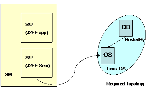
Figure 7: Example of a deployed target –
initial deployment
In
the above diagram, a solution module (SM) consists of an SIU that
deploys a hosting environment (J2EE Server), and then deploys a
J2EE application into that server. The first step is to specify the
initial required topology, which consists of a Linux operating
system, and a relational database. The J2EE Server is to be
installed into the operating system.
The
second step is to specify the deployed topology which will be
created by the first SIU, and into which the J2EE application will
be deployed. The deployed target definition associates the J2EE
server target with the SIU that instantiates the
resource.
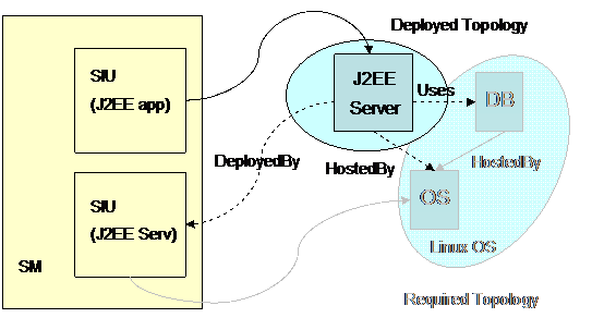
Figure 8: Example of a deployed target –
deploying into the deployed target
Each deployed target definition is an
instance of the iudd:DeployedTarget type. This type is illustrated
in the following diagram.
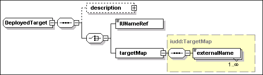
A deployed target definition has the following
attributes:
·
id [type=ID]
This REQUIRED attribute is used as an identifier for the
target.
·
type [type=iudd:AnyResourceType]
This REQUIRED
attribute is used to specify the target resource type.
A deployed target definition has the
following elements:
·
description [type=base:DisplayElement]
This OPTIONAL element allows to associate text labels and a
description with the target. See Section 17 for a general
description of display elements and their localization.
EITHER (element of a CHOICE)
·
IUNameRef [type=IDREF]
The value of this element is a reference to the IU within the root
IU that will deploy the target resource. The value MUST refer to
the IUName identifier of an IU specified within the base or
selectable contents of the root IU.
OR
(element of a schema CHOICE )
·
targetMap [type=iudd:TargetMap]
This element maps the target to a corresponding deployed
target in a referenced IU. Target maps are described in Section
5.6.3.
The
requisites element of the root IU identifies bundled requisites
that are distributed with the root IU. Bundled requisite IUs are a
form of Referenced IUs, see Section 6.2. Note that bundled
requisites need to have targeting information, so that it is known
where to install the individual SIUs. This means target maps need
to be provided in the topology section, for the bundled requisites
as well as the aggregated referenced IUs.
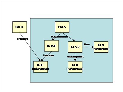
Figure
9: Federated and
bundled requisite IUs
Figure 9 illustrates a bundled requisite IU, IU “C”,
which may be used to satisfy the dependency expressed by IU
“A.2”.
A bundled requisite IU can be used to
create an instance satisfying the requirement of a contained IU
(inline or referenced) or it can be used to create an instance of a
federated IU.
In the first case, the bundled requisite IU is referenced via
the canBeSatisfiedBy element in a software check or in an IU check
within the contained IU. The created instance of the bundled
requisite IU MAY be deleted, if it is not shared by other IUs, when
the contained IU depending on that instance is deleted.
In the second case, the bundled
requisite IU is used to create an instance of the federated IU, if
one is NOT found. The created instance of the federated IU is meant
to be a shared component and SHOULD NOT be deleted before all
parent IUs are deleted.
In general, sharing of an IU MAY be
limited by specifying the maximumSharing identity constraint in its
definition. See Section 9.1.
The descriptor contains a definition for
each file that needs to be available during deployment together
with the root IU descriptor. Files in the following categories MUST
be defined in this section of the root IU descriptor:
·
A file containing the IU deployment descriptor (XML document) of a
referenced (or requisite) IU.
·
A file containing an artifact (descriptor) referenced in an SIU or
CU definition. See Sections 9.3 and 10.1 for a description of
artifacts.
·
A file referenced within any of the above artifacts.
Multiple file elements can be specified
within the files section. These are instances of the iudd:File
type, illustrated in the following diagram.
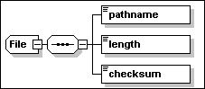
A file element definition has the
following attributes:
·
id [type=ID]
This REQUIRED attribute is used as a key to reference the file
element from other types. The value MUST be unique within the
descriptor.
·
compression [type=boolean]
An OPTIONAL
attribute specifying whether the file needs to be
automatically compressed during packaging and automatically
decompressed before use by actions (default is
“true”).
·
charEncoding [type=base:CharacterEncoding]
This is an OPTIONAL attribute. When specified it indicates that the
file contains text in the specified encoding. The code is
identified by the IANA character set name (http://www.iana.org/assignments/character-sets).
A file element definition has the
following elements:
·
pathname [type=base:RelativePath]
This REQUIRED element provides the relative path of the file image
relative to a logical source as specified in the IU Package Format
specification (see [IUPACK]). This logical source is the same for
all files defined in the root IU.
·
length [type=integer]
A REQUIRED element specifying the length of the file image as
included in the root IU, in bytes. If the file compression
attribute is specified, this is the length of the compressed
image.
·
checksum [type=base:CheckSum]
A REQUIRED element specifying the checksum of the file image as
included in the root IU. If the file compression attribute is
specified, this is the checksum calculated on the compressed
image
Installable units can be aggregated in a
tree-like hierarchy whose leaf nodes are Smallest Installable
Units (SIU) and Configuration Units (CU). The following
three aggregate types can be defined for installable units:
- Root Installable
Unit
This the top-level aggregate. As described in the previous section,
the IUDD defines a single root IU.
- Solution Module
(SM)
This IU aggregate type is the most general that can be defined
within a root IU, because installable units contained in the
solution module can be associated to different topology targets.
Solution modules are defined in Section 6.1.
- Container Installable
Unit (CIU)
This IU aggregate type contains
installable units that are associated to the same topology target.
The whole CIU is deployed onto each instance of the target.
Container Installable Units are defined in Section 6.4.
An independently packaged root IU may be
aggregated within another root IU by a reference made in the
aggregating root IU to the bundle file containing its deployment
descriptor (IUDD). An independently packaged root IU is referred to
in this specification as a referenced IU. Referenced IUs are
described in Section 6.2.
A root IU may be shared by one or more root
IUs, in which case it is referred to as a federated IU. This
relationship is declared in the federating root IU by means of
installable unit checks. Federated IUs are defined in Section
6.3.
The following restriction MUST be satisfied by
all of the IU aggregates defined in this specification:
An IU aggregate MUST NOT have two children
with the same UUID.
See Section 12.5.1 for a motivation of the
above restriction.
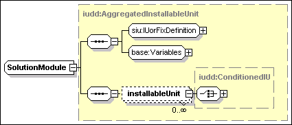
A solution module is a type of
aggregated installable unit, as described in Section 5.3.
Specifically, it is a multi-target installable unit, and therefore
SHOULD NOT specify a target reference. The structure of a solution
module is illustrated in the above diagram.
Each installableUnit element contained
in a solution module is an instance of the type iudd:ConditionedIU,
illustrated in the following diagram.
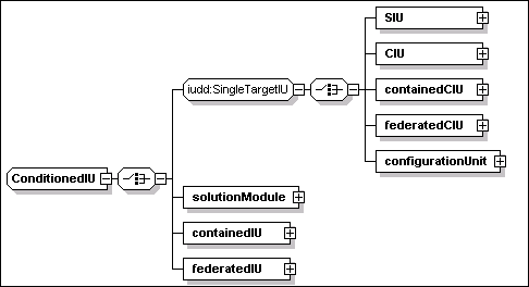
These installable units are either
targeted at a single hosting environment (SIU, CIU, containedCIU,
federatedCIU, configurationUnit), or at multiple hosting
environments (solutionModule, containedIU, federatedIU).
The installableUnit element
[type=iudd:ConditionedIU] has the following attributes:
·
targetRef [type=IDREF]
This is an OPTIONAL attribute. If specified the value MUST refer to
one of the targets defined in the topology, see Section 5.6. The
targetRef MUST be specified if the aggregating IU is a multi-target
IU and the conditioned IU is a single-target IU (e.g. a CIU or a
referenced IU with a targetRef attribute on the root IU). If the
aggregating IU is a single-target IU then the targetRef attribute
MAY NOT be specified: if it is specified, it MUST have the same
value as the aggregating IU’s target.
·
condition [type=base:VariableExpression]
This is an OPTIONAL variable expression representing a condition.
The latter determines whether the installable unit should be
installed. The default is “true”. See Section 8.3 for a
description and syntax of conditional expressions.
·
sequenceNumber [type=nonNegativeInteger]
This OPTIONAL attribute can be used to control the order of
install. See Section 12.4.
Each installableUnit element
[type=iuddConditionedIU] includes one (XML schema choice)
among the following elements:
·
SIU [type=siu:SmallestInstallableUnit]
See Section 9.
·
CIU [type=iudd:ContainerInstallableUnit]
See Section 6.4.
·
containedCIU [type=iudd:ReferencedIU]
This is a single-target referenced IU. See Section 6.2.
·
federatedCIU [type=iudd:FederatedIU]
This is a single-target federated IU. See Section 6.3.
·
configurationUnit [type=siu:ConfigurationUnit]
This element defines a configuration unit. See Section 10.
·
solutionModule [type=iudd:SolutionModule]
This is a nested solution module definition.
·
containedIU [type=iudd:ReferencedIU]
This is a multi-target referenced IU. See Section 6.2.
·
federatedIU [type=iudd:FederatedIU]
This is a multi-target federated IU. See Section 6.3.
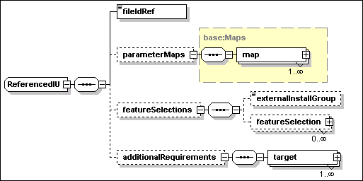
A referenced IU is defined by an
instance of iudd:ReferencedIU, the type illustrated in the above
diagram.
A referenced installable unit has the
following attribute:
·
IUName [type=ID]
This is a REQUIRED attribute by which the installable unit MAY be
referenced within the root IU. The value MUST be unique within the
descriptor.
A referenced installable unit has the
following elements:
·
fileIdRef [type=IDREF]
This element is REQUIRED. The value is a reference to the file that
contains the descriptor for the referenced installable unit.
·
parameterMaps [type=base:Maps]
This is an OPTIONAL element, defining a set of parameter maps. See
Section 6.2.1 for a definition of parameter maps.
·
featureSelections [anonymous type]
This is an OPTIONAL element, defining a set of feature selections.
It consists of the following elements:
o
externalInstallGroup [type=token]
This element is OPTIONAL. The value SHOULD match the name of an
install group in the referenced IU. If specified, this install
group specifies the initial selections for features within the
referenced IU. Otherwise, the default install group for the
referenced IU is used to determine initial feature selections. If
no explicit or default install group is specified, no features are
selected via group definitions.
o
featureSelection [anonymous type]
Zero or more instances of this element can be specified to provide
OPTIONAL further feature selections. Each selection identifies the
name of the feature in the referenced IU (externalName) and whether
it should be selected or not.
§
externalName [type=token]
This element is REQUIRED. The value SHOULD match the name of a
feature (name [type=token]) defined in the referenced IU.
§
selection [type=iudd:Selection]
This element is REQUIRED. This type allows to specify one of
the following enumerated values: “not_selected” and
“selected”.
·
additionalRequirements [anonymous type]
This element is OPTIONAL. It may be
used to specify additional requirements consisting of
solution-level checks and requirements that are to be applied in
addition to any checks and requirements defined within the
referenced IU, to the specified target. These MAY be used to
further constrain the use of an installable unit: for example to
restrict the install of a J2EE Server to use one specific database
product, where the J2EE Server may be capable of using multiple
database products. They MAY also be used to specify additional
resource requirements: for example, if a diskspace consumption
requirement of 100MB is specified within the referenced IU, and one
of 50MB is specified in the solution module, the overall
requirement for this IU in the context of the solution is 150MB.
These additional requirements do not override checks defined in the
referenced IU, so they MAY NOT be used to specify more permissive
checks. One or more instances of the following target element are
REQUIRED:
o
target [anonymous type]
This element has the following attribute:
§
targetRef [type=IDREF]
The targetRef of the target. This MUST correspond to the target
identifier of a target or deployed target defined in the
descriptor.
Each target definition has the
following elements:
§
checks [type=siu:CheckSequence]
The set of checks to be performed on the target. See Section 7.1
for a definition of checks.
§
requirements [anonymous type] (sequence of
siu:Requirement)
The set of requirements to be met on the target. See Section 7.2
for a definition of requirements.
A parameter map maps one or more
variables defined within the root IU to parameter variables of a
referenced installable unit. Input parameters in the referenced IU
that do not have a parameter map SHOULD be initialized with their
specified default value. Parameter maps MAY be used to override these default
values. These maps SHOULD NOT be used to override the value of
queries or derived variables. The type defining maps –
base:Maps – is illustrated in the following
diagram.
Each map in the set includes the
following elements to map a variable in this descriptor into a
parameter defined within the referenced IU:
·
internalName [type=IDREF]
This element is REQUIRED. The value SHOULD be a reference to a
variable that is in scope, i.e. that is defined in a parent
aggregate of the referenced IU. See Section 8.1.7 for a definition
of variable scope.
·
externalName [type=NCName]
This element is REQUIRED. The value SHOULD match the name
attribute [type=ID] of a parameter variable defined in the
referenced IU. See Section 8.1.1 for a definition of parameter
variables.
The type base:Maps is also used in different contexts for mapping
IUDD variables to artifact variables (see Section 9.5). For this
reason the map element includes an attribute – direction
– that can be used (only for check artifacts) to specify the
direction of the mapping (“in” or “out”).
Only the default value (“in”) is appropriate for a map
appearing in the context of a referenced IU definition.
During install, if an IU is specified inline, a new
dedicated IU instance will be created (unless it is an update or
fix IU). However, for a referenced IU, a decision may be taken to
share an existing IU instance. Such a shared referenced IU is known
as a federated IU. A federated IU is defined by a set of IU checks
that identify acceptable IU instances, and a bundled requisite IU
(see Section 5.7) that may be used to create a new instance if an
existing IU cannot be selected.
Figure 9 illustrates the different possible relationships
between contained IUs. IUA.1 and IUA.2 are inline and have
HasComponent relationships (i.e. dedicated containment) with SM A.
IU B is a referenced IU (i.e. it has its own root IU and a separate
descriptor), and also is dedicated. However, IU E is a referenced
IU which is federated, which means it may be shared by an external
IU such as SM D.
A federated IU is defined by an instance
of iudd:FederatedIU, the type illustrated in the following
diagram.
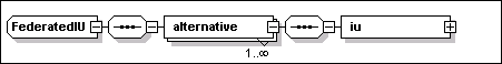
A federated installable unit has the
following attribute:
·
IUName [type=ID]
This is a REQUIRED attribute by which the installable unit MAY be
referenced within the root IU. The value MUST be unique within the
descriptor.
A federated installable unit defines a
set of one or more alternatives:
·
alternative [anonymous type]
This element is REQUIRED. Each alternative is defined by an IU
Check:
o
iu [type=base:IUCheck].
See Section 7.3.6 for a definition of IU checks. Within each IU
Check, the canBeSatisfiedBy element SHOULD be specified and MUST
identify the bundled requisite IU (declared within the requisites
element of the root IU) that could be installed to satisfy the
dependency. The IU Check SHOULD NOT specify the iuNameRef or
featureIDRef elements, which are intended for specifying
internal dependencies.
The reason for allowing a federated IU
definition to contain multiple alternatives (IU checks) is that the
required function may be provided by each member of a family of
related software units that do not share the same UUID (e.g.
different types of database).
Two alternatives in the same federated
IU definition SHOULD NOT specify the same UUID. This restriction is
necessary to support the deployment of bundled updates to federated
IUs (see Section 11.4).
Note that contained IUs (referenced or
in-line) are dedicated components of their aggregating IU and
SHOULD be deleted when their parent is deleted. By contrast,
federated IUs are shared components and SHOULD NOT be deleted
before all dependent IUs are deleted.
When a referencedFeature definition in a
feature that is selected, see Section 5.4.2, is associated to
the federated IU, an IU instance MUST have the referenced feature
installed to be eligible to satisfy an IU check in the federated IU
definition. An implementation MAY deploy a new instance if a
bundled requisite is specified via the canBeSatisfiedBy element.
Some implementations MAY support installing the requested feature
on an existing instance that does not have the feature
installed.
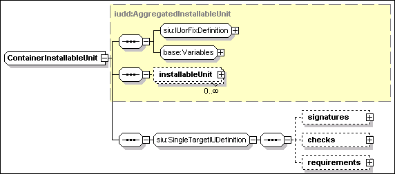
The
above diagram illustrates elements that are defined in a container
installable unit.
The
container installable unit is a type of AggregatedInstallableUnit
targeted at a single hosting environment. A definition of
iudd:AggregatedInstallableUnit is provided in Section 5.3.
A CIU has the following
attributes:
·
IUName [type=ID]
This is a REQUIRED attribute by which the installable unit MAY be
referenced within the root IU. The value MUST be unique within the
descriptor.
·
hostingEnvType [type=siu:AnyResourceType]
This OPTIONAL attribute is used to specify the resource type of the
IU target hosting environment, e.g. an operating system type, or a
J2EE application server type. When specified, the value of this
attribute SHOULD be equal to the one specified by the type
attribute of the target onto which the CIU is installed, see
Section 5.6.1. The latter is identified by the targetRef attribute
of the installableUnit element defining this SIU. The IU hosting
environment type may be specified to exploit tooling support for
the prevention of incorrect targeting. The type of this attribute
is defined as a union of the XML type QName and rtype:RType.
Therefore, a user defined resource type can be specified as a QName
value. Standard enumerated values for this field are defined
in rtype:Rtype. When specified, the value of this attribute
SHOULD be equal to the one specified by the hostingEnvType
attribute of the target onto which the CIU is installed. The latter
is identified by the targetRef attribute of the installableUnit
element defining this CIU. by the target identified hosting
environment.
Each installableUnit element in a CIU
[type=iudd:ConditionedIU] includes one (XML schema choice)
among the following elements:
·
SIU [type=siu:SmallestInstallableUnit]
See Section 9.
·
CIU [type=iudd:ContainerInstallableUnit]
See Section 6.4.
·
containedCIU [type=iudd:ReferencedIU]
This is a single-target referenced IU. See Section 6.2.
·
federatedCIU [type=iudd:FederatedIU]
This is a single-target federated IU. See Section 6.3.
·
configurationUnit [type=siu:ConfigurationUnit]
This element defines a configuration unit. See Section
10.
A
CIU CANNOT aggregate any of the multi-target installable unit types
defined by iudd:ConditionedIU, although this restriction is not
enforced in the schema.
The
schema group siu:SingleTargetIUDefinition defines additional
elements that are common to a CIU and an SIU, namely signatures,
checks and requirements. Checks and requirements are defined in
Section 7, while signatures are defined in Section 13.
Section B contains an example of a container installable unit.
A dependency is a requirement that a
certain condition involving the results of one or more elementary
checks, SHOULD be satisfied by a topology resource. A
software dependency is a requirement involving the result of
a software check, defined in Section 7.3.5, or the result of
an installable unit check, defined in Section 7.3.6.
The IUDD schema implements a separation
between checks and requirements. The result of a check may provide
information about the target resources and can be used to condition
the install behavior. Requirements formally express one or more
alternatives, one of which at least MUST be satisfied in order for
a component to be installable, or for an instance of a target to be
selected.
Checks and requirement MAY be used within the
topology target definition, illustrated in Section 5.6.1, to
declare the selection and validation criteria for the
target.
Single-target installable unit definitions,
see Section 6.4, MAY include checks and requirements defining the
IU specific dependencies. These MAY be dependencies on the
installable unit hosting environment target as well as any other
target defined by the topology.
Requirements MAY also be defined for contained
referenced IUs, see Section 6.2, in addition to those already
stated in the referenced IU descriptor.
Federated IU definitions, see Section 6.3, can
be also regarded as one form of software dependency.
The checks that can be performed on a
single managed resource fall into several categories, each of which
might imply different processing. These distinctions are made
either because different syntax or semantics apply to specifying or
evaluating the requirement or because greater flexibility is
offered to deployment application implementers to evaluate the
requirement efficiently. For example, the capacity requirements are
distinguished because they require specific syntax and
processing.
The IUDD supports the following check
categories:
·
Capacity of the hosting environment. This specifies a property of
the hosting environment, such as processor speed, which must
satisfy some minimum or maximum value.
·
Consumable resource allocation of the hosting environment. This
specifies resource, such as diskspace, that will be consumed by the
installation. Consumption requirements are cumulative across
installable units.
·
Value of named instance properties of the resource or hosting
environment.
·
Version of a resource, such as the resource software version or the
version of a supported standard or protocol.
·
Software requirements: the minimum and/or maximum version of
software identified by its UUID or name.
·
Installable unit requirement: the installation of a given IU.
·
Relationship with another manageable resource.
·
Custom checks, involving the execution of a defined command.
The element checks is an instance
of siu:CheckSequence. It can appear in a target definition (see
Section 5.6.1), in a single-target IU definition (see Section 6.4)
or in a referenced IU definition (see Section 6.2). The type
siu:CheckSequence is defined in the following diagram.
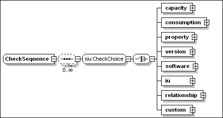
Different types of check are
supported: capacity, consumption,
property, version, software, iu, relationship
and custom.
All checks extend the base class
base:Check, which has the following two attributes that can
be specified for all types of checks:
·
checkId [type=ID]
This REQUIRED attribute associates a symbolic name to the check.
This name is used to refer to the result of the check in conditions
and requirements. The value MUST be unique within the
descriptor.
·
targetRef [type=IDREF]
This OPTIONAL attribute MAY be used to specify the target on which
the check MUST be performed. If specified, the value MUST
correspond to the target identifier of a target or deployed target
within the descriptor.
The targetRef attribute SHOULD NOT be specified for a check within
a topology target definition, or for a check within a referenced IU
definition. If it is specified, it MUST identify the target in
which the check definition itself is included.
If the targetRef attribute is NOT specified for a check within a
CIU, SIU or federated CIU, the check is applied to the target
hosting environment of the single-target IU in which it is
defined.
The targetRef attribute specified for a check within a
single-target IU MAY identify a target, TR that is
different from the IU target hosting environment, THE.
In that case, either the scope of the target TR is
“one” or there MUST be one or more relationships
connecting the IU target THE to the check target
TR, so that it is possible to navigate these
associations from any instance of THE to a single
corresponding instance of TR.
The following element is defined in the base
class base:Check. It MAY be specified for all types of checks:
·
description [type=base:DisplayElement]
This OPTIONAL element allows to associate text labels and a
description with the check. See Section 17 for a general
description of display elements and their localization.
The supported checks are described in
Sections 7.3 (Built-in checks) and 7.3.8 (Custom Check).
The result of a check is a boolean
value, which can be referenced through the checkId attribute of the
check. References to the results of a check are made in the
declaration of requirements, see Section 7.2 below, and in variable
expressions, see Section 8.2. In particular, a token
$(<checkId>) appearing in a variable expression is expanded
to the boolean value (“false” or “true”)
that is the result of the check identified by the
“<checkId>” value of the checkId attribute.
The following rules apply to check
scope.
·
Each one of the checks that are referenced within an IU MUST be
declared.
·
Check identifiers (checkId) MUST be unique within the descriptor.
They MUST also be distinct from any variable name within the
descriptor.
·
The scope of a check defined in an IU is that IU, and any inline
IUs that the IU contains.
·
The scope of a check defined on a target is any IU that is targeted
at that target. Variables definitions at the root IU level MAY
reference checks defined within a topology target.
·
Referenced IUs have a separate namespace for checks.
Requirements are specified by
identifying a set of combinations – alternatives
– that must be met. The requirement is met when any one of
these alternatives is met. Alternatives MAY have a priority
indicator, so that it is possible to determine which alternative
should be preferred when more that one satisfies the associated
checks.
The check combination in each
alternative consists of a list of the checks to be performed, which
may either be specified by reference, or included in-line. All of
the items in the check combination MUST be satisfied.
Each check reference SHOULD correspond
to a check that is within scope, i.e. it is defined within the
installable unit on which the requirement is specified; or within a
parent of that installable unit; or within the target of the
installable unit. It SHOULD NOT refer to a check in a sibling
installable unit.
Multiple requirements can be defined
within an IU or a target definition. The following criteria
determine whether a requirement should be declared in an IU or in
the target where the requirement needs to be satisfied:
·
A dependency that originates from the IU should usually be declared
in the IU and not in the target. This approach implies that if the
IU is not selected for install, the requirement is not imposed, and
a larger set of target instances is potentially eligible to install
the remaining selected IUs.
·
A requirement that is not specifically associated to a software
unit but is needed for the target to act its role in the solution
should be declared at the target level. See 4.5.1 for a discussion
of the different implications to declare a requirement for target
selection versus validation.
Each requirement element is an instance
of siu:Requirement, the type illustrated in the following
diagram.
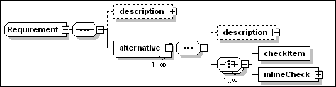
Each requirement defines one or more
alternatives. At least one alternative MUST be satisfied for the
requirement to be met. The failure to meet any requirement that is
defined by an IU should cause the IU installation to fail before
any action (with the exception of actions implementing custom
checks) is executed, unless the install program provides some form
of override policy. Both requirements and alternatives have a
description element that can be used to document the intent
of the declaration. See Section 17 for a general description
of display elements and their localization.
Within each IUDefinition, requirements
are specified against targets and installable units using the
schema described above. Further solution-level requirements may be
specified against referenced IUs, see ReferencedIU in Section
6.2.
A requirement element has the
following attributes:
- name
[type=ID]
This REQUIRED attribute provides an internal identifier of the
requirement.
- operations
[type=base:ListOfOperations]
This OPTIONAL attribute defines the list of lifecycle operations
performed on the IU for which the requirement should be evaluated.
Each item in the list MUST be one of the enumerated values defined
in base:Operation, namely:
-
- Create
- Update
- InitialConfig
- Migrate
- Configure
- VerifyIU
- VerifyConfig
- Repair
- Delete
- Undo
The assumed default, if the
attribute is not specified, is “Create”.
Each alternative element, within
a requirement, is an instance of an anonymous type with the
following attributes:
- name
[type=ID]
This REQUIRED attribute provides an internal identifier of the
alternative. The value MUST be unique within the root IU.
Each alternative has an associated boolean value. This boolean
value is “true” for an alternative that is
selected (based on the results of the associated checks and its
priority). The value is “false” for an alternative that
is not selected (either because one of the associated checks is not
met, or because there are other satisfied alternatives with a
higher priority.
References to the boolean value of an alternative can be made in
variable expressions. As an example, a token $(altName) appearing
in a variable expression is expanded to the value
(“false” or “true”) that is associated to
an alternative identified by the “altName” name
attribute.
Therefore, the boolean value of an alternative can be used in
conditional expressions to determine the selection of units, see
Section 9, or to determine the setting of a derived variable, see
Section 8.1.2.
- priority
[type=nonNegativeInteger]
This OPTIONAL attribute associates a non negative integer priority
value to the alternative. A requirement MAY define multiple,
non-exclusive alternatives. Multiple alternatives MAY be satisfied
when the unit is able to deploy and configure itself in different
ways, depending on the environment conditions. In order to
determine the “use” relationships that the IU instance
establishes with its pre-requisites it is important to know which
one of the possible configuration alternatives is implemented
during install.
The priority attribute SHOULD be specified when there are
non-exclusive alternatives in a requirement, more than one of which
can be simultaneously satisfied, unless these should be treated as
having the same priority (see below).
Specifying the same or no priority value for multiple alternatives
within the same requirement is interpreted as a declaration that
any one of the satisfied alternatives in this priority group could
be equivalently exploited. An implementation MAY request further
external input to select one or more of these alternatives, e.g.
during an interactive install.
Each alternative
is defined as a sequence of elementary checks whose result should
be verified. An elementary check is either referred to by the
checkItem element – a reference to a predefined
elementary check – or it can be defined inline by the
inlineCheck element.
A checkItem element within an
alternative has the following attributes:
- checkIdRef
[type=IDREF]
This REQUIRED attribute is a reference to the corresponding check
and, implicitly, to the variable containing the boolean result of
that elementary check.
- testValue
[type=boolean]
This OPTIONAL attribute defines the value of the check result for
which the alternative is satisfied. When the attribute is not
specified, the default value “true” is assumed.
Specifying a value of “false” means that the check
result MUST be the boolean “false” for the alternative
to be satisfied. In the case of a software check, this means that
the specified software IU is an “ex-requisite”.
An inlineCheck element MAY be used
instead of a checkItem element to specify a check directly within
an alternative element, that is, without making a reference to the
result of an elementary check that is performed before the user
input phase. An inline check is an instance of the group
siu:CheckChoice, already illustrated in Section 7.
Uses relationships are established
during install between an installable unit and other software
instances that constitute a dependency for the IU being created.
The specific relationships being established are determined by the
software dependencies declared in the IU and, in case of
requirements with multiple alternatives, by the specific
alternatives that were satisfied. The alternatives that are
satisfied at install time SHOULD continue to be met during the
unit’s life-cycle.
7.2.2
Example – Install requirements
The following example assumes that an SIU, implementing a JAVA
application can be installed on an operating system hosting
environment with the following requirements:
·
The SIU requires 0.2 Megabytes (200K) of free disk space.
·
The SIU requires 30 Megabytes of temporary disk space during
install.
·
The OS must be Windows 2000, Windows XP or Red-Hat Linux.
·
The required maintenance levels of Windows 2000 are SP3 or SP4.
·
Only the versions of Red-Hat between 7.2 and 8.1 are supported
·
The DB2 product is required.
·
The SIU supported DB2 version on Linux is 7.1
·
On Windows the SIU supports any version of DB2 between 7.2 and
8.1.
·
The ACME Personal Firewall product (any version) must not be
installed on Windows.
·
The SIU requires an IBM JRE.
·
The SIU supported JRE version on Linux is 1.3.1.
·
On Windows the SIU supports any JRE version between 1.3.1 and
1.4.1.
·
On Windows the SIU requires the IBM GS Kit v 4.0.2.49.
Here, for the sake of explaining custom checks, it is assumed that
the last requirement cannot be checked by means of a standard
software check. This situation might occur when the pre-requisite
software is deployed by a native installer and signature
information is not available to perform its discovery.
Let us assume that the following elementary checks, each one
referred to by the value of the checkId attribute, are defined
within the checks section of the IU definition.
·
Permanent_Disk_Space_Check
·
Temporary_Disk_Space_Check
·
Windows_2000_Check
·
Windows_XP_Check
·
Linux_Check
·
Windows_version_Check
·
Linux_version_Check
·
db2_for_Windows_Check
·
db2_for_Linux_Check
·
JRE_for_Windows_Check
·
JRE_for_Linux_Check
·
ACME_Personal_Firewall_Check
·
GSK4_WinRegistry_Check
Each one of these checks is explained in detail in the following
sections. With the above assumptions, the SIU requirements
can be expressed by the following XML fragment.
<requirement name="Install_Common_Reqmt"
operations="Create">
<alternative
name="isDiskSpaceAvailable">
<checkItem checkIdRef="Permanent_Disk_Space_Check"
/>
<checkItem checkIdRef="Temporary_Disk_Space_Check"
/>
</alternative>
</requirement>
<requirement name="Install_Dependencies_Reqmt"
operations="Create">
<alternative
name="isLinux_Alternative_Satisfied">
<checkItem checkIdRef="Linux_Check" />
<checkItem checkIdRef="Linux_version_Check" />
<checkItem checkIdRef="db2_for_Linux_Check" />
<checkItem checkIdRef="JRE_for_Linux_Check" />
</alternative>
<alternative
name="isWin2K_Alternative_Satisfied">
<checkItem checkIdRef="Windows_2000_Check" />
<checkItem checkIdRef="Windows_version_Check" />
<checkItem checkIdRef="db2_for_Windows_Check" />
<checkItem checkIdRef="JRE_for_Windows_Check" />
<checkItem checkIdRef="ACME_Personal_Firewall_Check"
testValue="false" />
</alternative>
<alternative
name="isWinXP_Alternative_Satisfied">
<checkItem checkIdRef="Windows_XP_Check" />
<checkItem checkIdRef="db2_for_Windows_Check" />
<checkItem checkIdRef="JRE_for_Windows_Check" />
<checkItem checkIdRef="ACME_Personal_Firewall_Check"
testValue="false" />
</alternative>
</requirement>
There are two requirements in the above
example that are both declared to apply to the “Create”
operation. The first one factors the common requirements (permanent
and temporary space) that must be satisfied on any operating system
platform. There is a single alternative in this requirement, and it
does not have an associated name. The second requirement can be
satisfied by any one of the listed alternatives (three). Of the
following checks
·
Linux_Check,
·
Windows_2000_Check and
·
Windows_XP_Check
only one is expected to be possibly
“true” on a given operating system hosting environment.
This fact makes the three alternatives mutually exclusive
and it therefore eliminates the need of assigning each alternative
a priority.
Some installable units may not need to
declare requirements for any operation other than Create. This is
the case if it can be assumed that the execution of other
operations like Configure or Delete should not require additional
resources. In general however, there may be extra consumption
resources (such as temporary disk space) that are needed during any
of the successive operations (Configure, Verify) that may be
performed during the IU life-cycle.
Requirements can be added that list the
checks that must be executed when executing one or more operations.
In the current example, let assume that there are actions, within
this unit of software, executing a configuration program during the
Configure operation. Also assume that this configuration program
need some temporary disk space to run. A second requirement can be
added to the sequence causing the following checks to be executed
during Configure:
·
Ensure there is enough temporary space for the configuration
program to execute. This requires to define a new check
(ConfigData_Temp_Space_Check)
The following XML fragment illustrates
the added requirement.
<requirement name="Configure_Reqmt"
operations="Configure">
<alternative
name="isDiskSpaceForConfigureAvailable">
<checkItem checkIdRef="ConfigData_Temp_Space_Check"
/>
</alternative>
</requirement>
In this example, an SIU MAY initially
configure itself to work with one or more database systems: DB_X,
DB_Y or DB_Z This situation might be expressed as a requirement
with three alternatives, respectively associated to the following
variables:
·
isDBX_Installed,
·
isDBY_Installed, and
·
isDBZ_Installed.
DB_X and DB_Y are the preferred choice:
there may be Create and InitialConfig artifacts in the SIU that
install and initially configure the IU to work with DB_X, DB_Y or
both DB_X and DB_Y. The SIU should only install and initially
configure the code for working with DB_Z if neither of the other
databases are installed.
Multiple artifact sets can be
associated to the SIU, see Section 9.3, each one through a different unit element.
Each unit element is conditioned, so it is possible to use the
results of checks to determine which unit should be processed
depending on the environment. Assume now that there are three
independent artifact sets associated to the SIU, each one capable
of deploying and configuring code to work with one specific
database. The units (artifact sets) associated to the above
databases are controlled by the following conditions:
·
DB_X unit condition:
“isDBX_Installed”;
·
DB_Y unit condition:
“isDBY_Installed”;
·
DB_Z unit condition:
“isDBZ_Installed AND NOT (isDBX_Installed OR
isDBY_Installed)”.
Declaring a priority for each of the
above alternatives is a means to make the installer aware of the
unit’s install and configuration intents without any need for
the installer to infer the same information from an analysis of the
conditions which depend on each alternative variable.
This is obtained by assigning the
isDBZ_Installed alternative priority = 1 (the lowest) and by
assigning the same and higher priority value – 2 – to
the other two alternatives.
<requirement name="ConfigureDatabases"
operations="Install">
<alternative
name="isDBX_Installed" priority="2">
<checkItem checkVarName="DBX_Check" />
</alternative>
<alternative name="isDBY_Installed" priority="2">
<checkItem checkVarName="DBY_Check" />
</alternative>
<alternative name="isDBZ_Installed" priority="1">
<checkItem checkVarName="DBZ_Check" />
</alternative>
</requirement>
As explained in Section 7.2.1 above,
the Uses relationships of the installable unit are determined by
the alternatives that are satisfied at install time and that are
part of the set with the highest assigned priority value. The
selected alternatives SHOULD continue to be satisfied during the
entire life-cycle of the installable unit.
A referenced installable unit
definition, see Section 6.2, MAY include additional
requirements that need to be satisfied by one or more topology
targets defined in the aggregating root IU. In that case, both the
requirements specified within the referenced IU descriptor and in
the aggregating root IU MUST be processed: these additional
specifications do NOT override any requirements stated in the
referenced IU descriptor. An implementation MAY choose to optimize
the checks it performs, e.g. it MAY only perform the most stringent
version range check or capacity check; it SHOULD check the total
consumption requirement.
Checks described in this Section can be
performed without providing user code.
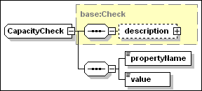
A capacity check is used to check the
value of a named property defining some capacity of the target
hosting environment. Each hosting environment type should define
the set of capacity properties that it supports and the units in
which these are expressed.
A capacity check element has the
following attributes and elements, in addition to the ones
inherited by base:Check.
·
type [anonymous type]
This OPTIONAL attribute may assume one of the following enumerated
values:
o
“minimum” (default)
The value of the named property MUST be equal or exceed the value
specified in the check definition.
o
“maximum”
The value of the named property MUST NOT exceed the value specified
in the check definition.
·
propertyName [type=base:PropertyName]
This REQUIRED element is used to specify the name of a hosting
environment capacity property.
·
value [type=base:VariableExpression]
This REQUIRED element is used to specify the threshold value
(maximum or minimum) of the property. If there are two capacity
checks for the same property and type= “minimum” only
the one with the highest value needs to be considered. If there are
two capacity checks for the same property and type=
“maximum” only the one with the lowest value needs to
be considered.
7.3.1.1
Example
In the following example,
“Processor/CurrentClockSpeed” is assumed
to be the name of a property exposing the processor frequency in
MegaHertz in the operating system hosting environment, and the
check is used to determine whether the processor speed is at least
400Mhz.
<capacity checkId="ProcessorSpeed_Check"
type="minimum">
<propertyName>Processor/CurrentClockSpeed</propertyName>
<value>400</value>
</capacity>
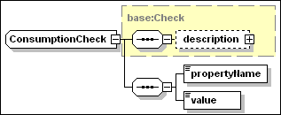
A consumption check is used to check
the availability of resources to be consumed on the hosting
environment. Typical examples of consumption properties on the
operating system hosting environment are disk space and memory. The
consumption requirement can be temporary or permanent. Multiple
consumption requirements for the same property on the same
container are automatically cumulated. Each hosting environment
type should define the set of consumption properties that it
supports and the units in which these are expressed.
A consumption check element has the
following attributes and elements, in addition to the ones
inherited by base:Check.
·
temporary [type=boolean]
When this OPTIONAL attribute has a value of “true” the
requested quantity of the named property is only needed during
installation. The default value is “false”.
·
propertyName [type=base:PropertyName]
This REQUIRED element is used to specify the name of a hosting
environment consumption property.
·
value [type=base:VariableExpression]
This REQUIRED element is used to specify the consumed amount of the
property. The value of the named consumption property MUST be equal
or exceed the sum of the values specified for the same property
over the installable units being deployed to the same hosting
environment..
7.3.2.1
Example
“TotalVisibleMemorySize”
and “FileSystem/AvailableSpace” are assumed to be
the names, in the following example, of properties exposed by the
operating system hosting environment which respectively determine
the core memory available for applications, in bytes, and available
disk space for file allocations. The checks determine if 131072
bytes of memory can be allocated to the IU, when in the running
state, and if 30.3 megabytes of temporary disk space are available
during installation.
<consumption
checkId="Memory_Check">
<propertyName>TotalVisibleMemorySize</propertyName>
<value>131072</value>
</consumption>
<consumption
checkId="Temporary_Disk_Space_Check"
temporary="true">
<propertyName>FileSystem/AvailableSpace</propertyName>
<value>30</value>
</consumption>
Note that there may be multiple filesystems in the
operating system that can satisfy the consumption requirement. The
above diskspace check will be satisfied if any of the filesystems
can satisfy the requirement. Note, however, that it is the
cumulative amount of diskspace that must be satisfied by a single
filesystem. If checks may be satisfied by multiple filesystem
instances, the requirement should be expressed using the targetRef
attribute on each check. Each check would indicate the logical
instance of a “Filesystem” resource hosted by the
operating system that is to satisfy the check.
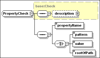
A property check is used to check the
value of a property defined for a manageable resource. Each
resource type should define the set of properties that it
supports.
A property check has the following
elements, in addition to the ones inherited by base:Check.
·
propertyName [type=base:PropertyName]
This REQUIRED element is used to specify the name of a property
being checked on a target resource.
The property check definition MUST include one of the three
following elements (members of a CHOICE)
·
pattern [type=string]
This element provides a string value to be interpreted as a regular
expression. The string value MUST be a valid instance of an XML
pattern facet. The regular expression SHOULD match the property
(string) value.
·
value [type=base:VariableExpression]
The property value MUST be identical to the one provided by this
element.
·
rootOfPath [type=base:VariableExpression]
This element provides a value to be interpreted as the full path
name of a given resource (e.g. a file), in which case the property
specified by the propertyName element should provide the
path name of a unique context for that type of resource (e.g. a
filesystem where files are stored). There is a single target
instance satisfying the check (see an example in the following
section). The name of properties that support this variant of
the check must be obtained from the documentation of each target
resource.
7.3.3.1
Examples
In the following example,
“OsType” is assumed to be the name of a property
exposing the operating system type according to the definition of
the “OperatingSystem” type in CIM 2.8, see
[CIM2.8].
<property
checkId="Windows_2000_Check">
<propertyName>OsType</propertyName>
<value>Windows
2000</value>
</property>
<property
checkId="Windows_XP_Check">
<propertyName>OsType</propertyName>
<value>Windows
XP</value>
</property>
<property checkId="Linux_Check">
<propertyName>OsType</propertyName>
<value>LINUX</value>
</property>
In
the following example, “root” is assumed to be the
property exposed by a file system type of resource, representing
the root of path names for all files and directories stored in a
file system instance. The following property check is satisfied by
the unique instance hosting the directory whose path name is
declared by the rootOfPath element.
<property checkId="FileSystem_Check"
targetRef="FileSystem_Target">
<propertyName>root</propertyName>
<rootOfPath>$(InstallDirectory)</rootOfPath>
</property>
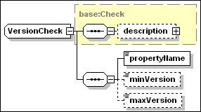
A version check is used to check the
value of a property of a target resource that has the
characteristics of a version. The actual names of properties
holding version information should be obtained from the
documentation of each specific resource.
Any version property associated to a
generic resource or hosting environment MUST have values in the
range defined for the vsn:GenericVersionString type. The format and
comparison rules for version strings are defined in Section
19.
A version check element has the
following elements in addition to the ones inherited by
base:Check.
·
propertyName [type=base:PropertyName]
This REQUIRED element is used to specify the name of a property
whose values MUST be in the format defined by the
vsn:GenericVersionString type.
At
least one of the following two elements MUST be
specified.
·
minVersion [type=vsn:GenericVersionString]
This is the minimum value that can pass the version
check.
·
maxVersion [type=vsn:GenericVersionString]
This is the maximum value that can pass the version
check.
7.3.4.1
Example
In the following example,
“version” is assumed to be the name of a property
exposing the Windows operating system version and service pack
level in a format compatible with vsn:GenericVersionString.
<version checkVarName="Windows_version_Check">
<propertyName>version</propertyName>
<minVersion>5.0.2195.3</minVersion>
<maxVersion>5.0.2195.4</maxVersion>
</version>
It should be noted that for a property
to qualify for version identification it MUST be possible to
determine which one of two possible values is an antecedent of the
other. This MAY be obtained by combining into the version property
information that may be associated to different
“native” properties. In the above example, information
relative to the Windows 2000 release (5.0) and version
(2195+ServicePack_4) is arranged in four version parts. A
definition of the actual structure of the version property being
checked should be obtained from the documentation of each specific
resource.
A software check is used to determine
whether a software resource is hosted in the target hosting
environment. Software resources include software that has been
installed by means other than the descriptor defined in this
specification. This contrasts with the installable unit check
described in the following section, which is intended to determine
the presence of a deployed installable unit in the hosting
environment.
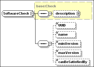
A software check has the following
attributes, in addition to the ones inherited by
base:Check.
·
type [type=base:RequisiteType]
This OPTIONAL attribute can assume one of the following two
values:
o
“pre_requisite” (default)
A “pre_requisite” must be installed before the
dependent IU is installed.
o
“requisite”
A “requisite” must be installed before the dependent IU
is Usable.
·
exactRange [type=boolean]
This OPTIONAL attribute determines whether the check may be
satisfied by a backwards-compatible version of the software
resource. This attribute SHOULD NOT be specified – it SHOULD
be ignored if it is specified – when the UUID element is NOT
specified (see below). The value defaults to “false”,
which means that the check CAN be satisfied by a
backwards-compatible version: i.e. the check will be passed when a
newer version than maxVersion is found which declares itself to be
backward compatible with a version level comprised between
minVersion and maxVersion.
A software check has the following
elements, in addition to the check description element
inherited from base:Check. All the elements are OPTIONAL. However
at least one of UUID and name MUST be specified.
·
UUID [type=base:UUID]
The UUID of an installable unit, if one exists, that defines the
required unit of software.
·
name [type=base:PatternOrValue]
The type of this element has an OPTIONAL boolean attribute
– pattern.
o
pattern [type=boolean]
When the element does NOT
specify this attribute, OR the element does specify the pattern
attribute with a value of “false” –
“false” is the default – the content string is
used to perform an equality comparison test with the name of
a software resource hosted by the target.
When the element is
specified with the pattern attribute value of “true”
the string content MUST be a valid instance of an XML pattern facet
and it is interpreted as a regular expression to match the
name associated to an installed unit of software hosted by the
target.
·
minVersion [type=vsn:GenericVersionString]
This is the minimum value that can pass the version
check.
·
maxVersion [type=vsn:GenericVersionString]
This is the maximum value that can pass the version
check.
·
canBeSatisfiedBy [type=IDREF]
Reference to the IUName of a bundled requisite in the root IU, see
Section 5.7. The bundled requisite SHOULD be installed on the
target instance if needed to satisfy a requirement associated to
this check.
A software check MAY specify only the
name of the software unit to be checked, OR it MAY specify
both the UUID and name.
A software check MAY specify
only the UUID of the software unit to be checked, in which
case the name of the software resource to be checked SHOULD be
retrieved from an IUDD descriptor associated to that resource. See
also the following Section 7.3.6 for a definition of installable
unit checks.
A software check SHOULD be used when
the required software resource MAY NOT have an IUDD or it MAY have
been deployed by means of a legacy installer, not enabled to
process and register IUDD information. Both UUID and name SHOULD be
provided when the IUDD for the software dependency is available, in
order to enable the use of a backward compatible hosted resource
that MAY have a different name (see below).
Different hosting environments may
support different types of software resources (e.g. installed
programs in the operating system; J2EE applications in the J2EE
environment), or may not host any form of software resource.
The software resource may be recorded
in a legacy registry that also includes version information. For
that reason, the version elements in a software check are instances
of the type vsn:GenericVersionString, and NOT of the
vsn:VersionString type, which defines a strict V.R.M.L
format (see Section 19).
A software check establishes a
dependency to a hosted software resource and not to an IU
instance.
The UUID information, when specified,
SHOULD be used to locate a matching IU descriptor. If an IU
descriptor matching the UUID is found whose version and backward
compatibility declarations make a corresponding IU instance a
candidate to satisfy the software dependency, the name
specified in that descriptor is used to perform the search over the
hosting environment hosted resources. An exact version matching is
required (a backward compatibility declaration is ignored, if
present) when the exact_range attribute is specified by the
software check. Note that the search on hosted resources would fail
if the IU was installed and registered with its UUID but it is not
known to the hosting environment by the name specified in the
descriptor. The diagram of Figure 10 illustrates the UUID
processing. In this example, it causes the selection of a
hosted resource with a later version and a different name.
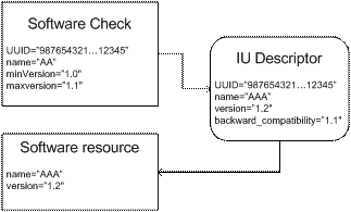
Figure 10: Use of UUID in a software
check
7.3.5.1
Example
<software checkVarName="db2_for_Linux_check">
<UUID>12345678901234567890123456789012</UUID>
<name pattern="true">(DB2|Universal
Database)</name>
<minVersion>7.1</minVersion>
</software>
<software checkVarName="db2_for_Windows_check">
<UUID>22345678901234567890123456789012</UUID>
<name pattern="true">(DB2|Universal
Database)</name>
<minVersion>7.2</minVersion>
<maxVersion>8.1</maxVersion>
</software>
<software checkVarName="JRE_for_Linux_check">
<UUID>13345678901234567890123456789012</UUID>
<name pattern="true">(IBM+.*J2RE)</name>
<minVersion>1.3.1</minVersion>
<maxVersion>1.3.1</maxVersion>
</software>
<software checkVarName="JRE_for_Windows_check">
<UUID>12445678901234567890123456789012</UUID>
<name pattern="true">(IBM+.*J2RE)</name>
<minVersion>1.3.1</minVersion>
<maxVersion>1.4.1</maxVersion>
</software>
<software
checkVarName="ACME_Personal_Firewall_Check">
<name pattern="true">(ACME+.*Personal
Firewall)</name>
</software>
The installable unit check differs from the
software check (see above section 7.3.5) in that it is
intended to perform checks on installable units based on identity
and other information declared in their IU descriptor. This
information SHOULD be persisted for an IU instance that is created
or modified. Ideally, this
information would be periodically verified against the actual
resources held in hosting environments.
The
IU check tests that an instance of a named IU, feature or fix
exists within a given hosting environment. If the IU spans hosting
environments, this check tests for the existence of any
subcomponent within the target hosting environment.
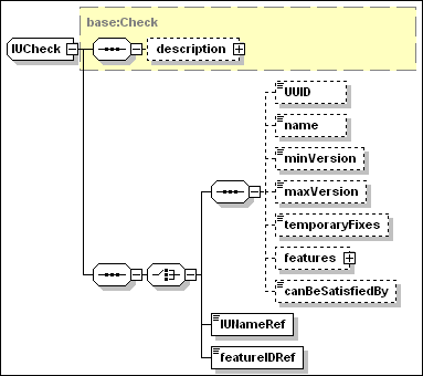
An
IU check supports different ways to identify the IU whose
availability needs to be checked. In particular, when the IUNameRef
OR the featureIdRef element is specified, the IU check is intended
to represent an internal dependency check. This type of
check does NOT require to be verified against a hosting environment
during Create. Note that an internal dependency does NOT cause an
implicit selection of a feature or an inline IU: the semantic is
that the dependent IU must be selected – if conditioned, the
condition MUST be satisfied – for the IU check to be
positively verified.
An installable unit check has the same
attributes as a software check, defined in the previous
Section 7.3.5.
·
type [type=base:RequisiteType]
This OPTIONAL attribute can assume one of the following two
values:
o
“pre_requisite” (default)
o
“requisite”
·
exactRange [type=boolean]
This OPTIONAL attribute determines whether the check may be
satisfied by a backwards-compatible version of the IU.
An installable unit check inherits a
description element from the base type base:Check. The IU check consists of either a
standard IU check, an internal IU dependency check,
or an internal feature dependency check. These three
variants of the check correspond each to an element of an XML
schema choice construct, and are separately described below, each
in a separate sub-section.
7.3.6.1
Standard IU Check
A standard IU check has the following
elements, in addition to the check description element
inherited from base:Check. All the elements are OPTIONAL. However
at least one of UUID and name MUST be specified.
·
UUID [type=base:UUID]
This is the UUID of the installable unit, as defined in the IU
identity.
·
name [type=token]
This is the name of the installable unit, as defined in the IU
identity.
·
minVersion [type=vsn:VersionString]
This is the minimum V.R.M.L. value that can pass the version
check.
·
maxVersion [type=vsn:VersionString]
This is the maximum V.R.M.L. value that can pass the version
check.
·
temporaryFixes [type=base:ListOfIdentifiers]
This is a list of NCName type of items. Each item identifies a
required temporary fix by a value that MUST correspond to the fix
name as specified by the fixName element in the fix
definition.
This element MUST list all the names of fixes that are REQUIRED to
be applied to the IU.
·
features [anonymous type]
If specified, this element contains a sequence of one or more name
elements, each one identifying a required IU feature:
o
name [type=token]
The value of this element MUST correspond to the name element in
the feature identity definition.
·
canBeSatisfiedBy [type=IDREF]
Reference to the IUName of a bundled requisite in the root IU, see
Section 5.7. The bundled requisite SHOULD be installed on the
target instance if needed to satisfy a requirement associated to
this check.
7.3.6.2
Internal IU Check
An
internal IU check specifies the internal identifier of an IU,
within the root IU. The check is verified – i.e. the check
result is “true” – if the identified IU is also
installed. The identified IU MAY be defined among the selectable
contents, in which case the result of the check depends on feature
selections, see Section 5.4. The identified IU MAY have an
associated condition, in which case the result of the check depends
on variables – including parameters, derived variables, check
results and requirement alternative results – that MAY be
referenced by the condition.
·
IUNameRef [type=IDREF]
This is a reference to the IU that MUST be installed for the check to be verified. The
value MUST match the IUName attribute of an IU within the
descriptor.
7.3.6.3
Internal Feature Check
An
internal feature check specifies the internal identifier of a
feature within the root IU. The check is verified – i.e. the
check result is “true” – if the identified IU is
already installed or is selected to be installed. The identified IU
MAY be defined among the selectable contents, in which case the
result of the check depends on feature selections, see Section 5.4.
The identified IU MAY have an associated condition, in which case
the result of the check depends on variables – including
parameters, derived variables, check results and requirement
alternative results – that MAY be referenced by the
condition.
·
featureIDRef [type=IDREF]
This is a reference to a feature that MUST be installed for the check to be verified. The
value MUST match the featureID attribute of a feature defined
within the descriptor.
Relationship checks describe a specific
relationship that MUST exist between a target and another
manageable resource. The structure of the relationship check is
illustrated in the diagram below:
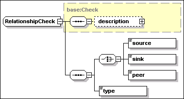
The relationship check inherits the
checkId and targetRef attributes from the base type
base:Check. In particular, the targetRef attribute identifies the
topology target that MUST satisfy the relationship check. The check
is specified in two parts.
1.
The identifier of the related target participating in the
relationship.
Exactly one of the following three elements MUST be specified
depending on whether the relationship has an implied direction
(such as Hosts) or is a peer relationship. The referenced target
MUST be defined within the root IU descriptor.
·
source [type=IDREF]
This element indicates that the target identified by the targetRef
attribute of the relationship check is the source of a
directional relationship with a related target identified by this
element.
·
sink [type=IDREF]
This element indicates that the target identified by the targetRef
attribute of the relationship check is the sink of a
directional relationship with a related target identified by this
element.
·
peer [type=IDREF]
This element indicates that the target identified by the targetRef
attribute of the relationship check and the one identified by this
element are in a peer relationship.
2.
The name of the required relationship type, specified by the
following element.
·
type [type=rel:Relationship]
This element is an instance of rel:Relationship, a type which
defines the range of admissible relationship types. This type is a
union of rel:StandardRelationship – defining a set of
standard association stereotypes – and the Name XML
type. An association stereotype defines a category of associations
(relationships) with a common semantics.
For example, if target A is to be the host of another target B,
then the relationship is specified as:
<target id="A" …>
…
<relationship
checkId=”AHostsB”>
<sink>B</sink>
<type>Hosts</type>
</relationship>
…
</target>
Conversely, if target A is to be hosted
by target B, then the relationship is specified as:
<target id="A" …>
…
<relationship
checkId=”BHostsA”>
<source>B</source>
<type>Hosts</type>
</relationship>
…
</target>
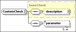
A custom check defines the execution of
a check artifact on a target.
Like any artifact (see Section 9.5)
check artifacts may have their variables initialized via a
parameter map. The same check artifact could be referenced by
multiple custom checks testing different sets of conditions, each
set of conditions being associated to the values of variables
passed into the artifact. The actual definition of the custom check
artifact to be executed is not included within each individual
check. Artifacts referenced by custom checks are defined within the
root IU element customCheckDefinitions introduced in Section 5.3,
and illustrated in the following diagram.
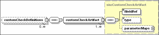
Custom check definitions in the rootIU
element are OPTIONAL.
A customCheckArtifact element –
instance of siu:CustomCheckArtifact, derived from the siu:Artifact
type described in Section 9.5 – includes the same
elements that are common to all artifact definitions, namely:
·
fileIdRef [type=IDREF]
This REQUIRED attribute
is a reference to a file element in the root IU defining the
bundled artifact descriptor file. It MUST be a valid reference to a
file element within the root IU files element.
·
type [type=siu:ArtifactFormat]
This OPTIONAL
attribute is used to declare whether the artifact defines actions
or resource property definitions. The supplied default value
(“ActionDefinition”) is appropriate for a custom check
artifact and it SHOULD NOT be overridden with a different value.
This restriction SHOULD be enforced by the implementation; although
it is not enforced by the schema.
·
parameterMaps [type=base:Maps]
This OPTIONAL attribute is used to declare mappings between
variables in the IUDD and variables defined in the artifact. This
is a sequence of map elements, each one associating an IUDD
variable (internalName) to an artifact variable
(externalName). Parameter maps are explained in Section 9.5
for SIU and CU artifacts. Each map element has a direction
attribute. SIU and CU artifacts only support the default value
(“in”) meaning that the IUDD variable is used to
initialize the artifact variable. However, a map associated to a
check artifact can specify the direction attribute to be
“out” thus requiring that the value of the artifact
variable MUST be obtained at the end of the check artifact
execution and used to set the corresponding IUDD
variable.
It is REQUIRED that a check artifact
define a “checkResult” variable whose value at the end
of the check artifact execution MUST indicate the boolean result
(“true” or “false”) of the custom check. A
parameter map for the “checkResult” artifact variable
SHOULD NOT be defined (the result boolean value is used to set
the variable implicitly associated to the check, see Section
7.1.1). As a “side-effect” of executing a custom check
with parameter maps specifying the “out” value of the
direction attribute, one or more IUDD variables may have their
values changed.
While most of the semantic associated
to a custom check depends on the above custom check artifact
definition, the behavior of the check also depends on the values of
IUDD variables that are passed (direction “in”) into
the artifact variables. As explained below, the custom check
(invocation) allows to specify new values for these IUDD variables,
whose change MUST be effective prior to the mapping.
A custom check has the following
attribute in addition to the ones inherited from
base:Check.
·
artifactIdRef [type=IDREF]
This REQUIRED
attribute is a reference to a custom check command definition. It
MUST be a valid reference to a CustomCheckArtifact element within
the root IU element customCheckdefinitions.
A custom check may include one or more
instances of the following element
·
parameter [anonymous type]
The type of this element is derived from base:VariableExpression.
This element is used to to specify a value for a variable which
must be set with the specified value before any parameter map
with direction “in” is processed in the corresponding
check artifact definition. The element includes the following
attribute
o
variableNameRef [type=IDREF]
This attribute is used to identify the variable for which a value
if provided.
Some IUDD
variables appearing with direction “in” in the artifact
definition may not need to be set for each specific check, i.e they
retain the same value across different checks, in which case these
variables do not need to be set by a parameter element in the
custom check.
Note that implementing software
pre-requisite checking through custom checks (external commands)
makes it impossible for an implementation to record a relationship
between the unit being installed and the pre-requisite software
resources.
The following is an example custom
check declaration:
<custom artifactIdRef="winRegCustomCheck"
checkId="GSK4_Win_Registry_Check">
<parameter
variableNameRef="Win_Reg_Hive">HKEY_LOCAL_MACHINE</parameter>
<parameter
variableNameRef="Win_Reg_Key">SOFTWARE\IBM\GSK4\CurrentVersion\Version</parameter>
<parameter
variableNameRef="Win_Reg_Type">REG_SZ</parameter>
<parameter
variableNameRef="Win_Reg_Value">4.0.2.49</parameter>
</custom>
The above example assumes that
“winRegCustomCheck” is the identifier of a check
artifact defined in the IU descriptor, checking the value of a
specified registry key for equality against a specified
value. The check artifact definition corresponding is given
below:
<customCheckArtifact
artifactId="winRegCustomCheck">
<fileIdRef>WinRegistryCheckArtifact</fileIdRef>
<parameterMaps>
<map>
<internalName>Win_Reg_Hive</internalName>
<externalName>Reg_Hive</externalName>
</map>
<map>
<internalName>Win_Reg_Key</internalName>
<externalName>Reg_Key</externalName>
</map>
<map>
<internalName>Win_Reg_Type</internalName>
<externalName>Reg_Type</externalName>
</map>
<map>
<internalName>Win_Reg_Value</internalName>
<externalName>Reg_Value</externalName>
</map>
</parameterMaps>
</customCheckArtifact>
In this example, the parameter
elements in the custom check (invocation) assign values to the four
parameter variables that are mapped to artifact variables within
the custom check artifact definition.
Variables support late binding of additional
information to an IU descriptor. This information may be obtained
from user input, from a target property query or from other
sources. Variables can be referenced within a schema when defining
the value of an attribute or element that is an instance of
base:VariableExpression. Symbolic references to a variable are
substituted by the variable value when the expression is evaluated.
Expressions producing a boolean result value are used in
conditions. Conditions MAY be associated to an installable unit
definition. They MAY be also associated to expressions within a
derived variable definition.
A variable can be one of several types,
as described below:
·
It is a parameter, provided by user input, response file or from an
encapsulating installable unit (see Section 8.1.1).
·
It is derived from a variable expression (see Section 8.1.2).
·
It is defined as a query against a target (see Section 8.1.3).
·
It is defined as a query against an IU instance, returning the IU
instance discriminant. This is the value that uniquely identifies
an IU instance within a hosting environment, for example, the
install location for an IU installed into the operating system (see
Section 8.1.4).
·
It is specified as a resolved target list (see Section 8.1.5).
·
It is specified by an IU update as a variable inheriting its value
from a variable that was defined in a previous level of the same IU
instance (see Section 8.1.6).
In addition to the above variables,
which are explicitly declared, a variable expression MAY contain a
reference to the boolean result of a check, see Section 7.1.1, or
to the boolean result of a requirement alternative, see Section
7.2.
One or more variables MAY be defined by
the element variables within an IU. This is a sequence of
one or more variable elements, instances of base:Variable. Each one
identifies a named variable that is needed to deploy the
installable unit. The variable MAY have a locale-sensitive
description.
The above six forms of a variable
definition are all represented in the following diagram for the
schema type base:Variable
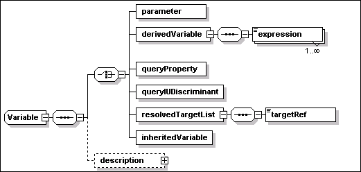
A variable MUST specify the following
attribute
·
name [type=ID]
This REQUIRED attribute is an identifier that can be used to refer
to the variable. The value MUST be unique within the
descriptor.
A variable MAY specify the following
element
·
description [type=base:DisplayElement]
This OPTIONAL element allows to associate text labels and a
description with this variable. See Section 17 for a general
description of display elements and their localization.
A variable MUST specify one of the six
elements defined by the XML schema choice construct. These
are defined in the sections below.
The parameter element defines a
parameter variable. The value MAY be provided by user input,
response file or from an encapsulating installable unit descriptor
via a parameter map.
·
parameter [anonymous type]
The following attributes MAY be specified for this
element
o
defaultValue [type=base:VariableExpression]
This OPTIONAL attribute provides a default initial value for the
parameter variable. If no default value is specified, and no value
is provided by user input, response file or parameter map from an
aggregating IU, the value of the parameter variable is undefined.
An error SHOULD be generated when trying to access a parameter with
an undefined value.
o
transient [type=boolean]
This OPTIONAL attribute is used to indicate that this variable
contains information (e.g. a password) that SHOULD NOT be
permanently stored, either because it is transient – the
current value may become invalid – or because the current
value represents sensitive user information. If needed on
successive life-cycle operations associated to a deployed IU
instance, the current value will have to be supplied.
8.1.1.1
Example
<variable
name="installToAllUsers">
<parameter
defaultValue="true"/>
</variable>
In the absence of an overriding value,
the above definition of a variable named
“installToAllUsers” causes the default value
(“true”) to be retained.
The derivedVariable element
defines a derived variable.
·
derivedVariable [anonymous type]
The element MUST include one or more instances of the following
elements, each one defining a candidate value for this
variable:
o
expression [anonymous type]
The type of this element is derived from base:VariableExpression,
and it includes the following OPTIONAL attributes:
§
condition [type=base:VariableExpression]
This attribute is used to specify a condition for this expression.
If more than one variable expression is provided, each one SHOULD
be qualified using a condition. The value of this expression should
be assigned to the derived variable if this condition is
“true”. The variable expression for this attribute may
include references to the boolean result value of a check or
to the boolean result of a requirement alternative. A derived
variable depending on the outcome of checks and alternatives may be
made available within artifacts, through parameter maps, to
determine the appropriate behavior of actions.
§
priority [type=nonNegativeInteger]
The attribute specifies a priority for this expression. A priority
MUST be specified when multiple expressions are defined. If
multiple expressions have their conditions satisfied, the variable
will be set to contain the value of the expression with the highest
priority value (where “5” is a higher priority than
“1”). Two expressions SHOULD NOT specify the same
priority.
8.1.2.1
Example
<variable
name="install_root">
<derivedVariable>
<expression condition="$(Windows_Check)">C:\Program
Files</expression>
<expression
condition="$(Linux_Check)">/usr/opt</expression>
</derivedVariable>
</variable>
In the above example, the variable
named “install_root” is set to the value
“C:\ProgramFiles” or to the value “/us/opt”
depending on alternative conditions. In this example, it is assumed
that the variable expression associated to each condition is the
boolean result (“true” or “false”) of an
elementary check. It is also assumed that the two checks
cannot be simultaneously satisfied on the same hosting environment,
therefore there is no need to specify a priority.
The queryProperty element
defines a variable whose value is the result of a query. Queries
MAY be specified against a target that resolves to multiple
physical instances, based on the scope value (“all” or
“some”).
When the variable is defined within a
single-target IU and the target T is identical to the IU hosting
environment, the IU instance being deployed to a physical instance
Ti of the IU target T SHOULD “see” the
variable to contain the property value obtained from the same
instance.
A query property variable defined
within a multi-target IU SHOULD result in a comma-separated list of
values when the target resolves to multiple physical instances. All
lists associated to different query property variables defined for
the same target SHOULD have the value associated to a given target
instance in the same position. The ordering of values in the list
SHOULD be consistent with the sequence of target identifiers
associated to a resolvedTargetList variable defined for the same
target, see Section 8.1.5.
·
queryProperty [anonymous type]
This element defines the name of a property to be queried, and
optionally the target on which the query SHOULD be performed.
o
propertyName [type=base:PropertyName]
This REQUIRED attribute defines the name of the property to be
queried.
o
targetRef [type=IDREF]
This OPTIONAL attribute may be used to specify the target on which
the query SHOULD be performed. A variable definition within a
single target IU is NOT REQUIRED to specify the target: if a target
is not specified, the query is performed on the IU target hosting
environment. This attribute SHOULD be specified if the variable
definition is NOT within a single target IU. If the attribute is
specified, the value MUST be a valid reference to a target of a
deployed target within the root IU.
If targetRef is specified for a single target IU and it is
different from the IU target, then EITHER the target has a scope of
“one” OR it SHOULD be possible to navigate
relationships connecting the IU target to the query target so that
one and only one instance of the query target is reached from the
IU target. In the first case, the single target instance SHOULD be
queried. In the second case, the instance of the single target IU
being deployed to an instance “X” of the IU target will
“see” the variable to contain the property value from
the instance “Y” of the query target that is
reached by navigation of the existing relationships.
8.1.3.1
Example
<variable name="database_name">
<queryProperty property="name"
targetRef="tDatabase" />
</variable>
In the above example, a query variable
is defined to obtain the name of a database. The example assumes
that the topology target “tDatabase” defines a
manageable resource that exposes the needed database name via the
“name” property.
The queryIUDiscriminant element
defines a variable whose value is the IU discriminant of an
installed IU instance. The IU instance discriminant is the value
that uniquely identifies an IU instance within a hosting
environment, for example, the install location for an IU installed
into the operating system.
·
queryIUDiscriminant [anonymous type]
This element defines the IU instance to be queried by reference to
an IU check, see Section 7.3.6, within the scope of the IU.
Use of a discriminant variable requires that the specific instance
of an IU satisfying the IU check MUST be identified. When multiple
IU instances satisfy the check, the user or the install runtime
MUST select one instance. The returned discriminant value MUST be
the one associated with the instance that is used within the root
IU to satisfy the check.
The check referenced by a variable defined at the root IU level
MUST be defined within a root IU topology target, as these are the
only checks in scope for a variable in the root IU. However, the
variable MUST not be referenced outside the scope of an IU that is
aimed on that target.
o
iuCheckRef [type=IDREF]
This REQUIRED attribute MUST correspond to the checkId of an IU
check defined in the descriptor: it SHOULD correspond to the
checkId of a check that is in scope, see Section 7.1.1.
8.1.4.1
Example
<variable name="Linux_JRE_Home">
<queryIUDiscriminant
iuCheckRef="JRE_for_Linux_check" />
</variable>
In the above example, the variable
named “Linux_JRE_Home” is set to the value of the
install location of the installable unit instance satisfying the IU
check named “JRE_for_Linux_Check”.
A resolvedTargetList is a variable
whose value consists of the manageable resource IDs (handles) of
the actual resource or resources corresponding to a specified
target. It is assumed that a manageable resource id can be
represented by a string that does NOT contain a comma character.
Where a target resolves to more than one actual resource, the
result is a comma-separated list. In that case, the ordering of
identifiers in the list SHOULD be the same applied to the sequence
of values of any property query on the same target that produces a
list result, see Section 8.1.3.
A typical usage scenario for this
capability is when a deployment application delegates some aspects
of deployment or configuration. In this case, the hosting
environment to which deployment is delegated needs to be aware of
the target topology for the components within its domain. Example:
an SIU represents a J2EE application that is targeted at
TDM – a topology target representing the domain
manager of a J2EE administrative domain. However, one of the
deployment parameters that needs to be specified for the SIU
artifact is the list of servers within the domain onto which the
application needs to be deployed. Another topology target
TAS is defined in this example to represent the specific
set of J2EE application servers in the J2EE domain. A
“Hosts” relationship is required between
TDM and TAS, and additional requirements may
be defined for TAS. A resolvedTargetList variable
defined for TAS provides the needed list of
servers that the SIU can pass into the artifact using a parameter
map, so that it can be processed by the hosting environment
TDM.
·
resolvedTargetList [anonymous type]
The resolvedTargetList element defines a variable whose value is
set to contain a list of manageable resource IDs, one for each
selected instance of a topology target identified by the targetRef
attribute.
o
targetRef [type=IDREF]
This REQUIRED attribute is used to specify the target whose
resolved instances are identified by this variable. The value MUST
be a valid reference to a topology target or deployed target in the
root IU.
8.1.5.1
Example
<variable name="Actual_Targets">
<resolvedTargetList targetRef="Solution_Server" />
</variable>
The inheritedVariable element
specifies a variable that SHOULD inherit its value from a variable
defined in a previous level of the same IU instance. An
inheritedVariable SHOULD only be defined within an IU update or
within a temporary fix.
·
inheritedVariable [anonymous type]
This element does NOT specify any content. The name of this
variable, as defined by the corresponding attribute, SHOULD be used
to locate the corresponding persisted value associated with an
existing IU instance.
8.1.6.1
Example
<variable name="definedInBase">
<inheritedVariable/>
</variable>
The following rules apply to variable
scope and override.
1.
Variable names MUST be unique within the descriptor.
2.
The scope of a variable is the IU in which it is defined, and any
inline IUs and CUs that the IU contains.
3.
Variables defined in the root IU have global scope within the
descriptor. An iuDiscriminant variable defined in the root IU can
be referenced only within IUs that are associated to the same
target whose check definition is referenced by the variable
definition.
4.
Referenced IUs have a separate namespace for variables. The only
interaction is via parameter maps. An IU aggregating referenced IUs
MAY use a parameter map to redefine a variable in the referenced
IU.
Some elements of the IUDD schema are
instances of base:VariableExpression. The latter is a simple XML
type derived by restriction from the XML base string type:
<simpleType
name="VariableExpression">
<restriction
base="token">
<pattern
value="([^$]*($[^(])*($\([a-zA-Z_]+[0-9a-zA-Z_]*\))*)*"/>
</restriction>
</simpleType>
The restriction forces the substring
“xxxx” contained within an enclosing substring
“$(xxxx)” to be a valid variable identifier, as defined
by the type NCName.
The consumer of an element that is an
instance of the base:VariableExpression type MUST resolve the
variables in the string and substitute each “$(xxxx)”
token appearing in the variable expression with the value of the
corresponding variable.
A conditional expression MAY appear as
the value of a condition attribute in the following schema
elements within the IUDD:
·
An expression element, defined within the
derivedVariable element of a variable definition, see
Section 8.1.2;
·
An installable unit definition within the base or selectable
content of the root IU, see Section 6;
·
A unit element within an SIU or CU defining an artifact set,
see Section 9.3.
Conditional expressions also appear in
artifacts where they are used to condition actions and action
groups, see Section 14.
Check variables, property queries and
derived variables based on property queries MAY be used in
conditions. The use of parameters is permitted but discouraged, as
a condition is intended to represent an environmental constraint
and not a user selection. Resolved target lists and IU discriminant
variables SHOULD NOT be used in conditions.
A condition element is an
instance of base:VariableExpression, see Section 8.2. Once
variable substitution has
occurred in a condition, the resulting conditional expression MUST
be a (constant) XPath boolean expression, with the following
restrictions:
1.
When all the variable substitutions have been completed, the string
value of a condition element must be a valid XPath boolean
expression. The format of the XPath expressions is defined by the
XML Path Language (XPath) Version 1.0 (http://www.w3.org/TR/xpath).
2.
The boolean expression to which the condition element reduces after
variable substitutions SHOULD NOT contain any of the following:
·
Variables References
·
Node Sets Expressions, including functions returning a node
set.
·
Function calls.
These constraints SHOULD be enforced by
the tooling and validated by the installer.
condition="('$(win_drive)' != 'C:') and
('$(win_drive)' != 'Z:')"
Note that string literals can appear
within single quotes if the conditional expression attribute is
enclosed within double quotes, and vice versa. Note that operators
like “<” and “>” cannot be directly
typed within the conditional expression and MUST be escaped by, for
example using < and > respectively. Syntax details
are described at http://www.w3.org/TR/xpath.
Any variable that is declared in an
installable unit and which is first used in the Create or
InitialConfig operations, see Section 4.2, SHOULD have its
value set during the operation in which it is first used. The value
SHOULD then be saved and restored on successive lifecycle
operations.
A variable declared in a configuration
unit or that is declared in an installable unit and first used in
the Configure operation SHOULD be re-evaluated during each
Configure operation. The value MAY be saved for use on successive
VerifyConfig operations.
Conditions on IUs SHOULD be evaluated
during the Create or Update operation, in order to determine which
IUs should be installed. Subsequent life cycle operations SHOULD
NOT add or remove an installable unit based on the current
evaluation of a condition.
Conditions on configuration units SHOULD
be re-evaluated during each Configure and VerifyConfig
operation.
All checks SHOULD be re-evaluated in any
operation for which their value is needed to evaluate a
requirement.
This section defines the Smallest Installable
Unit (SIU) of software. This is specified in the schema file
siu.xsd. The aggregation of such elementary units into larger
aggregates is described in Section 6.
An SIU instance is defined by the
siu:SmallestInstallableUnit schema type illustrated in the
following diagram.
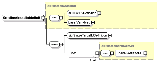
The SIU definition is an instance of the above
type. It includes the following attributes:
·
IUName [type=ID]
This REQUIRED attribute is an identifier of the IU element in the
instance document. It SHOULD NOT be confused with the IU identity
name, see Section 5.1. This attribute MAY be used to refer
to the IU from other elements within the descriptor.
·
hostingEnvType [type=siu:AnyResourceType].
This OPTIONAL attribute specifies the type of the SIU hosting
environment. When specified, the value of this attribute SHOULD be
equal to the one specified by the type attribute of the
target onto which the SIU is installed, see Section 5.6.1. The
latter is identified by the targetRef attribute of the
installableUnit element defining this SIU. The IU hosting
environment type may be specified to exploit tooling support for
the prevention of incorrect targeting. The type of this attribute
is defined as a union of the XML type QName and rtype:Rtype.
Therefore, a user defined hosting environment resource type can be
specified as a QName value. Standard enumerated values for resource
types are defined in rtype:Rtype. Tooling MAY constrain this
attribute to known valid hosting environment types (NOT all
resources are hosting environments).
The schema constructs
IUorFixDefinition, SingleTargetIUDefinition and
Variables are common to an SIU as well as to other
installable unit types defined in Section 6:
- IUorFixDefinition
This
element contains information about the identity,
constraints, obsoletedIUs and supersededFixes
of the installable unit. This information is relevant to both
single- and multi-target installable units. See Section 9.1.
- SingleTargetIUDefinition
This element contains information specific to single-target
installable units, such as signatures, checks and
requirements. Signatures are described in Section 13, while
the latter two elements – checks and requirements – are
described in Section 7.
- Variables
This element
contains information about variables, defined within the context of
the SIU. See Section 8 for a definition of variables and variable
expressions. Any variable that is referenced by a variable
expression within an SIU MUST be declared within the SIU. See
Section 8.1.7 for a definition of variable scope. The most
important use of variables, in an SIU, is in artifact parameter
maps, which associate variables defined in the SIU with variables
defined within the artifacts. See 9.5.
The SIU definition includes the following
element in addition to the above constructs:
- unit
[type=siu:InstallArtifactSet]
At least one instance of this element MUST be specified. The
content of this element defines one set of artifacts –
artifacts are separately bundled descriptors for actions OR
resource property definitions – associated to this SIU.
Artifact sets are described in Section 9.3.
The unit element may specify the following condition
attribute:
§
condition [type=base:variableExpression]
This OPTIONAL attribute defines a condition that, controls
the selection of the artifact set associated to the unit
element. At most one artifact set will be selected. This attribute
SHOULD NOT be specified when a single unit element is defined. The
attribute MUST be specified when multiple unit elements are
specified, in which case the conditions defined for each of them
SHOULD be constructed so that they are mutually exclusive: if they
are not, then an arbitrary selection between qualified artifact
sets MAY be made.
The main elements of an IU definition
are grouped by the siu:IUorFixDefinition XML group. The latter
contains information which is applicable to both single-target and
multi-target installable units: part of the elements apply to an
ordinary IU while other apply to a temporary fix. The following
diagram illustrates the part that applies to an ordinary IU (the
part of the diagram related to a temporary fix definition is not
expanded: it contains only the element fixIdentity, already
defined in Section 5.2).
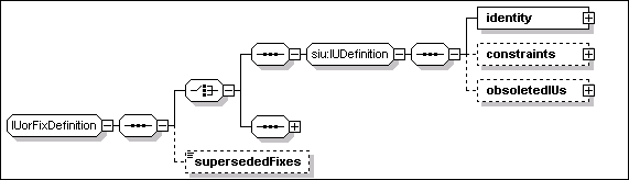
The identity element is defined
in Section 5.1. This section describes the other elements that can
be specified as part of an IU definition, namely
constraints, obsoletedIUs and supersededFixes.
Superseded fixes can be specified both in the context of an IU
definition and in the context of a fix definition.
- constraints [anonymous type]
This OPTIONAL element may be specified to include one or both of
the following two elements:
o
maximumInstances [type=nonNegativeInteger]
This
OPTIONAL element is the limit to the number of instances of the IU
that can be simultaneously present onto the same instance of a
target hosting environment. The number is unbounded when this
element is NOT specified.
o
maximumSharing [anonymous type]
This OPTIONAL
element is an instance of a complex anonymous type, extending
the XML nonNegativeInteger type. The numeric value of this element
is the maximum number of IU instances that MAY have a dependency on
one instance of this IU. Containment and software dependencies by
other IUs in the same IUDD MUST NOT be considered. Dependencies
from outside of the root IU MUST be considered. These include
simple “Uses” relationships (when this IU satisfies a
software dependency) as well as “Federates”
relationships (when this IU satisfies a federated IU
definition).
The following attribute MAY be used to further restrict the
use of this IU only by instances of an identified set of IUs.
§
sharedBy_List [type=base:ListOfUUIDs]
This OPTIONAL attribute is a list of UUID values
corresponding to IUs whose instances are allowed to make
shared use of this IU (within the sharing limits set by the numeric
value of the element).
- obsoletedIUs
[anonymous type]
This OPTIONAL element of the IU definition consists of a sequence
of one or more elements, each one defining one IUs that is made
obsolete by this installable unit. When installed in the
context of an Update operation, this IU deletes the obsoleted IUs
that are part of the same root IU instance. An IU SHOULD NOT
declare itself obsoleted (e.g. to have an instance of a previous
version removed).
o
obsoletedIU [anonymous type]
This element is used to specify the IU to be obsoleted. An
obsoleted IU SHOULD be physically deleted after installing
the IU which contains the obsoletedIU declaration. Deleting
obsoleted IUs at the end of the update process makes it possible to
migrate configuration data that the IU may hold. However,
this implies that there should be no intersection between resources
(files, objects, etc.) deployed by the obsoleted IUs and content
deployed by the updating IU, otherwise some of the new
content would be uninstalled when the obsoleted IU is deleted. If
multiple instances of the obsoleted IU exists within the root IU
instance being updated, these SHOULD be all deleted. This elements
contains an XML choice construct to select one OR the other among
the following two elements:
§
UUID [type=base:UUID]
The UUID to be used to locate the obsoleted IU instances.
§
name [type=token]
The identity name of the obsoleted IU instances.
-
supersededFixes [type=base:ListOfIdentifiers]
This OPTIONAL element can be specified for both an IU and a fix
definition. The type of this element is defined as an XML list of
NCName typed items. Each item in the list is used to specify a
value matching the name of the fix that is superseded. The fixName
element is part of a fix identity and it is described in Section
5.2.
Updates and temporary fixes, see Section 11, MAY consolidate the
contents of a previously applied fix into their content. This
information MAY be used by the change management system to
determine the appropriate action to take regarding the currently
installed fixes. If a fix or an update is applied that supersedes
another fix, then a check for the superseded fix may be satisfied
by the superseding fix. If an upgrade is applied and there are
fixes on the previous level that are not superseded by the upgrade,
it may be necessary to reapply those fixes.
Declaring a fix as superseded SHOULD NOT require an implementation
to take any action other than eliminating the IU-Fix association
after the superseding IU (or Fix) has been applied to the
target IU instance. That is, fixes declared as superseded by a Fix
or by an IU update are NOT REQUIRED to be rolled-back when the fix
or update is installed. The assumption is that a fix (or IU update)
B that supersedes a fix A must be robust enough to handle both the
case in which fix A is installed and the case in which it is not
installed. The system SHOULD be left in a consistent state in both
cases. See Section 11.3 for a discussion of updates to an
instance with non superseded fixes.
<constraints>
<maximumInstances>1</maximumInstances>
<maximumSharing
sharedBy_List="1234567890...123456789012">100</maximumSharing>
</constraints>
The above sample XML fragment defines
constraints for an IU of which there MUST be no more than one
instance. It also specifies that there could be a maximum of 100
dependent instances sharing the same instance of the IU. All of
these dependent IUs are instances with the specified UUID (the
sharedBy_List attribute has only one element).
<obsoletedIUs>
<obsoletedIU>
<UUID>12345678901234567890123456789000</UUID>
</obsoletedIU>
<obsoletedIU>
<UUID>12345678901234567890123456789001</UUID>
</obsoletedIU>
<obsoletedIU>
<name>ThisIUname</name>
</obsoletedIU>
</obsoletedIUs>
The
above sample XML fragment defines three obsoleted IUs. The first
two are identified by their respective UUID. The last one is
identified by its name.
<supersededFixes>PTF012345 PTF123456
PTF234567</supersededFixes>
The above sample XML fragment contains
a declaration that three temporary fixes are superseded by the IU
or fix whose definition contains the declaration.
A temporary fix is an installable unit
that is not part of the normal sequence of released versions. A
temporary fix MAY be a root IU, or an SIU, or any other type
of installable unit that MAY be defined as part of a root IU. What
makes it possible to distinguish a temporary fix from an ordinary
IU is the identity. The identity of temporary fixes is described in
Section 5.2.
Any IU
aggregate, including root IUs, that defines a temporary fix SHOULD
only aggregate IUs that are themselves temporary fixes.
When performing an installable unit
check that includes checks on temporary fixes, the check MUST list
all of the required fix names. See Section 7.3.6. Although one fix
may explicitly supersede another fix, there is no concept of the
“latest” fix superseding all previous fixes.
A fix MAY consolidate one or more of the
current temporary fixes. These are listed by the
supersededFixes element, which is described in the context
of an IU definition in Section 9.1.3.
Fixes MAY be categorized, by specifying the fixType
element in the fix identity.
·
fixType[anonymous type]
This OPTIONAL element may be used to specify one of the following
enumerated values:
o
“InterimFix”
Tested and verified fix available to customers. It may contain
fixes for one or several product defects and fixes for internally
discovered defects. It is typically made available to the
registered users.
o
“TestFix”
A temporary or uncertified fix with limited testing that is
supplied to one or several customers for testing, but is typically
not available for the general public. Typically, this type of fix
has little or no packaging, i.e. may be file
replacements.
o
“ProgramTemporaryFix”
An individual fix that is typically made available to all
customers. A PTF resolves one customer reported problem.
Two temporary fixes applying to the
same single-target IU instance MAY be subject to the following
relationships, which pose constraints on their installation:
·
ex-requisite
An instance SHOULD NOT have the two fixes simultaneously
applied;
·
co-requisite
An instance SHOULD have the two fixes simultaneously applied OR
none applied;
·
pre-requisite
This is a directional relationship. The fix declaring another fix
as a pre-requisite SHOULD NOT be applied if the latter is NOT
applied first.
In
principle, it is possible to express the above relationships using
IU checks, see Section 7.3.6. In practice, this results in complex
descriptors. For this reason the fix definition includes the
fixDependencies element. This element is expanded at the bottom of
the following diagram, whose other elements have been described in
Section 5.2.
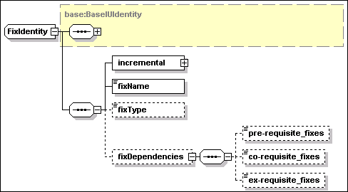
·
fixDependencies [anonymous type]
This OPTIONAL element may be specified to include one or more of
the following elements:
o
pre-requisite_fixes
[type=base:ListOfIdentifiers]
This OPTIONAL element is
used to specify a space separated list of fix names. Every one of
the listed fixes SHOULD be applied before this temporary fix can be
applied.
o
co-requisite_fixes
[type=base:ListOfIdentifiers]
This OPTIONAL element is
used to specify a space separated list of fix names. Every one of
the listed fixes SHOULD be available to be applied with this
temporary fix. The order in which the fixes are physically applied
is NOT specified and it SHOULD be irrelevant. This fix and all the
ones listed by this element SHOULD be applied before the updated IU
achieve the usable state.
o
ex-requisite_fixes
[type=base:ListOfIdentifiers]
This OPTIONAL element is
used to specify a space separated list of fix names. This temporary
fix SHOULD NOT be applied if any of the listed fixes is already
applied to the IU being updated.
<installableUnit>
<SIU IUName="PTF_1"
hostingEnvType="OSCT:Operating_System">
<fixIdentity>
<name>MyPDF Reader</name>
<UUID>12345678901234567890123456789012</UUID>
<incremental>
<requiredBase>
<minVersion>5.0.1</minVersion>
<maxVersion>5.0.4</maxVersion>
</requiredBase>
</incremental>
<fixName>PTF123456</fixName>
<fixDependencies>
<pre-requisite_fixes>PTF001234
PTF012345</pre-requisite_fixes>
</fixDependencies>
</fixIdentity>
<unit>
<installArtifacts>
<installArtifact>
<fileIdRef>PTF_1Actions</fileIdRef>
</installArtifact>
</installArtifacts>
</unit>
</SIU>
</installableUnit>
The above sample XML fragment contains
a complete definition of a temporary fix SIU. The identity element
defines the name and UUID of the IU to which the fix can be
applied. The fix name is “PTF123456” and it has fixes
“PTF001234” and “PTF012345” as
pre-requisites. The unit element describes artifacts associated to
this temporary fix SIU.
The unit element in an SIU
defines the artifacts to be used when performing life cycle
operations on the installable unit, see Section 4.2. An artifact is
a descriptor containing the definition of actions to be performed on
the hosting environment, or a definition of a set of resource
properties to be configured. The separation of the action
definition from the declarative IU dependency information permits a
supporting implementation where the IU descriptor is interpreted by
a generic change management component, whereas the actions are
interpreted by a hosting-environment specific component.
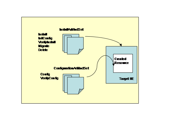
The above diagram illustrates the artifact sets.
There are two defined sets of artifacts. The first set handles the
lifecycle operations that are performed to install an IU. The
second set of artifacts handles the operations to configure or
reconfigure the IU.
An SIU contains one or more artifacts, each one
intended for use with a specific life cycle operation. As an
example, an Install artifact is needed for the Create and Update
operations, while an Uninstall artifact is needed for Delete. The
artifact is REQUIRED to be an XML document, but its exact content
beyond that is constrained only by the hosting environment,
although this specification does provide recommended formats
– the Action Definition and Resource property Definition
– that may be extended, see Sections 14 and 15. The intended
implementation is that the appropriate artifact is passed to the
hosting environment, which then uses the artifact to performing the
life cycle operation.
As SIU unit is an instance of
siu:InstallArtifactSet, and it describes the artifacts related to
the installation of software. Units are also defined for
configuration units (CU) units that are instances of
siu:ConfigurationArtifactSet, describing artifacts related to
configuration. This section describes the artifacts related to
installation. Those related to configuration are described in
Section 10.
The type siu:InstallArtifactSet is
illustrated in the following diagram.
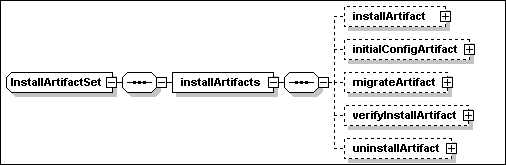
The following OPTIONAL elements
are instances of siu:UndoableArtifact – which is an
extension of the base type siu:Artifact, defined in Section
9.5, including the following attribute:
o
undoable [type=boolean]
This OPTIONAL attribute – default is “false”
– is used to identify whether the associated life cycle
operation can be performed in an “Undo” mode. Where
supported, an undoable operation supports a rollback operation,
where the installable unit is rolled-back to its state prior to
applying the operation. An implementation SHOULD support at least
the Update operation in “Undo” mode An implementation
MAY support only a single level of undoable Update, in which case
it MAY automatically commit a previous level.
The artifact types described by each one of the elements
illustrated in the above diagram are described in the Section 9.4
below.
·
installArtifact [type=siu:UndoableArtifact].
This OPTIONAL element SHOULD define an Install
artifact.
·
initialConfigArtifact [type=siu:UndoableArtifact]
This OPTIONAL element SHOULD define an InitialConfig
artifact.
·
migrateArtifact [type=siu: UndoableArtifact]
This OPTIONAL element SHOULD define a Migrate artifact.
The following OPTIONAL elements are
instances of the siu:Artifact type, described in Section 9.5
·
verifyInstallArtifact [type=siu:InstallArtifact]
This OPTIONAL element SHOULD define a VerifyInstall
artifact.
·
uninstallArtifact [type=siu:InstallArtifact]
This OPTIONAL element SHOULD define an Uninstall
artifact.
Artifacts are either applied to a
hosting environment to implement a software life-cycle operation;
or they are applied to a manageable resource to set or to verify a
specified configuration. Artifacts of the first type will be
generally referred to as “install artifacts”, while
artifacts of the second type will be referred to as
“configuration artifacts”.
Install artifacts are part of the
definition of a Smallest Installable Units (SIU) while
configuration artifacts are part of the definition of a
Configuration Unit (CU). Note that there are no artifacts
associated with an IU aggregate.
|
Artifact type
|
Description
|
|
Install
|
If the install artifact is
associated to a base SIU (or a full update SIU, see Section 11.1)
it can be used by the Create operation to create an instance of the
SIU.
If the artifact is associated
to an update (full or incremental) or to a fix, it can be used by
the Update operation to install the update (or the fix) to an
existing instance of the required base SIU.
A software instance is
initially created and then it is possibly modified by successive
update operations, each one applying the install artifact
associated to an update or fix SIU.
Actions defined in the install
artifact MAY refer to bundled files provided with the
packaged solution. Access to the bundled files referenced by the
install artifact is only supported by the Create, Update and Repair
operations. Other operations that MAY access the install artifact
(Delete, Undo, VerifyIU) do NOT have access to the referenced
bundled files. Other artifacts MUST NOT contain references to
bundled files.
|
|
InitialConfig
|
The initialConfig artifact is
used only for a base or a full update SIU, see Section 11.1.
A fix or an SIU defining an
incremental update MUST NOT specify an initialConfig artifact.
The artifact defines actions
that are needed to bring a newly created IU instance in the Usable
state. When this artifact is specified, the Create operation leaves
a newly created instance in the “Created” state,
to indicate that a successive InitialConfig operation is needed to
bring the instance to the Usable state. Otherwise, the newly
created instance transitions directly to the Usable state.
Actions defined in the
initialConfig artifact MUST NOT contain references to bundled
files.
|
|
Migrate
|
The artifact defines actions
that are needed to configure an updated IU instance.
The migrate artifact is used
only for a full update or an incremental update.
A fix or an SIU that cannot be
used to upgrade a base instance MUST NOT specify a migrate
artifact.
When this artifact is
specified, the Update operation leaves a modified instance in the
“Updated” state, to indicate that a successive Migrate
operation is needed to bring the instance to the Usable state.
Otherwise, the updated instance transitions directly to the Usable
state.
Actions defined in the migrate
artifact MUST NOT contain references to bundled
files.
|
|
VerifyInstall
|
The verifyInstall artifact is
used by the VerifyIU operation to perform integrity checking of an
SIU instance.
On some hosting environments
the VerifyIU operation MAY process the install artifacts
successively applied to the instance by updates and fixes.
Access to the actions defined
by the install artifact for creating or updating the SIU instance
may be exploited to identify resources, created as part of the SIU
instance, that need to be verified. As the SIU instance may have
passed through multiple updates, the VerifyIU MAY need to examine
multiple install artifacts.
Some hosting environments MAY
allow the SIU definition of the verifyInstall artifact to be a
reference to the SIU install artifact. In that case, the VerifyIU
operation SHOULD use the install artifact to identify the resources
(e.g. files) created as part of the install that need to be
verified.
Actions defined in the
verifyInstall artifact MUST NOT contain references to bundled
files.
|
|
Uninstall
|
The uninstall artifact is used
by the Delete operation to perform the removal of an SIU or
fix.
An update or fix that does not
introduce new resources as part of an existing instance (only
modifies pre-existing resources) SHOULD NOT specify an uninstall
artifact.
On some hosting environments
the Delete operation MAY process the install artifacts successively
applied to the instance by updates and fixes.
Access to the actions defined
by the install artifact for creating or updating the SIU instance
may be exploited to identify resources, created as part of the SIU
instance, that needs to be removed. As the SIU instance may have
passed through multiple updates, the Delete MAY require to examine
multiple install artifacts in reverse order.
Some hosting environments, MAY
allow the SIU definition of the uninstall artifact to be actually a
reference to the SIU install artifact. In that case, the Delete
operation SHOULD use the install artifact to identify the resources
(e.g. files) created as part of the install that need to be
removed.
Actions defined in the
uninstall artifact MUST NOT contain references to bundled
files.
|
As illustrated in the above table, a
single artifact can be accessed in the context of different IU
lifecycle operations. The following table lists the primary
artifact accessed by each operation.
|
Lifecycle Operation
|
Artifact Type
|
|
Create
|
Install artifact
|
|
InitialConfig
|
InitialConfig
artifact
|
|
Update
|
Install artifact
|
|
Migrate
|
Migrate artifact
|
|
Delete
|
[Uninstall artifact]
[Install artifact]
|
|
VerifyIU
|
[VerifyInstall
artifact] [Install artifact]
|
|
Repair
|
[Install
artifact]
|
|
Undo
|
[Install
artifact]
|
Note that the Undo operation MAY need to
access the install artifact to roll-back the last update applied to
an instance, but that MAY NOT be required on all hosting
environments. Analogously, the Repair operation MAY NOT need to
access the install artifacts of the IU instance being repaired. An
artifact type between square brackets, in the above table, MAY NOT
be accessed by the corresponding operation.
The type siu:Artifact, illustrated by
the following diagram, is the base type for all artifacts defined
within an artifact set.
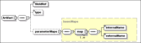
The only REQUIRED content of an artifact
definition, within the IUDD, is a reference to a bundled file
containing the actual artifact. The latter is itself a descriptor
of variables and actions or properties that MAY contain references
to other bundled files.
An artifact definition has the following
attributes:
·
HE_restart_required [type=boolean]
This OPTIONAL attribute – default is “false”
– specifies whether a hosting environment restart (in
case of an operating system hosting environment this would
correspond to a reboot) is REQUIRED after processing the
actions in the artifact. See Section 9.5.1.
An
artifact definition has the following elements:
·
fileIdRef
[type=IDREF]
This REQUIRED element is used to identify the bundled file
containing the artifact (XML descriptor). The value MUST be a valid
reference to a bundled file, see Section 5.8.
·
type [type=siu:ArtifactFormat]
This element is OPTIONAL. The assumed value, if the element is NOT
specified, is “ActionDefinition”. The type of
this element is a union of siu:StandardArtifact Format and NCName,
where the former enumerates the names of two standard artifact
formats. Any value in the range of NCName MAY be assigned to the
element to specify a user-defined artifact format.
The standard enumerated values are:
o
“ActionDefinition”.
See Section 14 for a definition of the proposed format for
artifacts of this type.
o
“ResourcePropertiesDefinition”.
See Section 15 for a definition of the proposed format for
artifacts of this type.
·
parameterMaps
[type=base:Maps]
This OPTIONAL elements maps variable names in the descriptor to
variable names that are meaningful in the context of the hosting
environment. The use of these variables is hosting-environment
specific. These MAY be used to initialize variables defined within
the artifact, see Section 14, OR they MAY be used directly by the
hosting environment. In particular, some of the external
variable names, in these maps, MAY identify variables that have a
special meaning to the hosting environment (e.g. install path).
Each map element can be used to specify the following
elements:
o
internalName
[type=IDREF]
This REQUIRED element is a reference to a variable defined within
the IUDD whose value is used to initialize a corresponding artifact
variable identified by the externalName element.
o
externalName
[type=NCName]
This REQUIRED element is used as a reference to avariable defined
within the artifact that MUST be initialized with the value of the
IUDD variable identified by the internalName element.
The map element also includes an attribute –
direction – that can be used to specify a reverse mapping
where the value of an artifact variable is used to set an IUDD
variable. The default value of this attribute
(“in”) is appropriate for an SIU or CU artifact,
as it corresponds to the above stated semantic of the internalName
and externalName mapping. A different value (“out”) can
be only specified for a check artifact (see Section 7.3.8). In
other terms, there is no provision for variables to be set as a
result of executing a SIU or CU artifact.
A restart of the hosting environment
runtime, e.g. an operating system reboot, SHOULD NOT be
directly invoked by actions in the artifact. The need for a restart
of the hosting environment MAY be indicated using the
HE_restart_required attribute (default “false”)
in the artifact definition. If this attribute is set to
“true”, the hosting environment SHOULD be restarted
after processing of the artifact has been completed.
The restart is NOT conditioned to the
occurrence of specific conditions (e.g. the presence of
locked files on an operating system hosting environment). However,
the restart MAY be postponed until after further IUs within the
same life cycle operation have also been processed within the same
hosting environment, provided that none of the IUs with a pending
restart are required as pre-requisites.
A pre-requisite IU MUST be brought to
the Usable state by performing the pending restart before other
dependent installable units can be installed.
In some cases it is possible and
preferable to determine the need for a restart while the target
hosting environment is processing the artifact. In order to support
this capability, a hosting environment MAY provide interfaces
– that actions supported within an artifact MAY leverage
– to notify the need if a restart. After notification, the
restart would be properly sequenced with other pending operations.
In that case the requirement for restart SHOULD NOT be normally
declared in the artifact definition.
A
configuration unit (CU) is an atomic unit of configuration. Like an
SIU, a CU can be specified as part of an aggregated installable
unit. The following differences exist between a configuration unit
and an SIU:
·
A CU does NOT have a unique identity and does not represent a
distinct entity with a defined lifecycle (e.g. that might be
recorded in a registry).
·
Configuration units can be targeted NOT only to hosting
environments, but also to any type of managed resource.
·
The life cycle operations applying configuration units to the
target managed resources are described in Section 4.3.
A configuration unit is an instance of
siu:ConfigurationUnit, the type illustrated in the following
diagram.
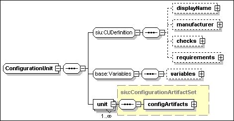
A configuration unit has the following
attributes:
- CUName [type=ID]
This REQUIRED attribute is an identifier of the CU definition
within the IUDD. This attribute MAY be used to refer to the CU from
other elements within the descriptor. It does NOT provide a
persistent global identifier.
- resourceType [type=siu:AnyResourceType]
This REQUIRED attribute is used to specify the resource type of the
CU target managed resource. The type of this attribute is defined
as a union of the XML type QName and rtype:RType. Therefore, a user
defined resource type can be specified as a QName value. Standard
enumerated values for this field are defined in
rtype:Rtype.
A configuration unit has the following
elements:
- displayName [type=base:DisplayElement]
This OPTIONAL element allows to associate text labels and a
description with the corresponding CU. See Section 17 for a general
description of display elements and their localization.
·
manufacturer [type=base:DisplayElement]
This
OPTIONAL element allows to specify the name and description of the
CU manufacturer. See Section 17 for a general description of display
elements and their localization.
- checks [type=siu:CheckSequence]
This OPTIONAL element includes a sequence of checks, see Section
7.1.
-
requirements
[anonymous type]
This OPTIONAL element includes a sequence of requirements, see
Section 7.2.
-
variables
[anonymous type]
This OPTIONAL element includes a sequence of variables, see Section
8.1.
-
unit
This REQUIRED element defined the configuration
artifact set for the CU. Artifact sets are introduced in Section
9.3. This element is an instance of siu:ConfigurationArtifactSet,
described in Section 10.1 below.
The type siu:ConfigurationArtifactSet is
illustrated in the following diagram.
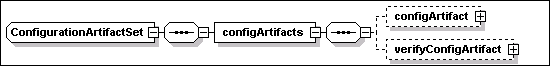
The following OPTIONAL elements
are instances of the type siu:Artifact, defined in Section 9.5. The
artifacts described by each one of the elements illustrated in the
above diagram are described in the Section 10.2 below.
·
configArtifact [type=siu:Artifact].
This OPTIONAL element SHOULD define a Configure
artifact.
·
verifyConfigArtifact [type=siu:Artifact]
This OPTIONAL element SHOULD define a VerifyConfig
artifact.
Each one of the above
artifact declarations MAY include information on its format through
the OPTIONAL type element. Standard enumerated values, see Section 9.5, are:
·
“ActionDefinition”
The artifact defines actions to be executed on a target hosting
environment. This format MAY be appropriate for a CU that
configures an IU instance through its hosting environment.
See Section 14 for a definition of the proposed format for
artifacts of this type.
·
“ResourcePropertiesDefinition”
The artifact defines property values. This is the preferred
format to define the configuration of a manageable resource.
See Section 15 for a definition of the proposed format for
artifacts of this type.
The artifacts
described in the following table are applied to a manageable
resource to set or to verify a specified configuration.
|
Artifact type
|
Description
|
|
Configure
|
The configure artifact is associated to a CU and it defines actions
to configure a resource. The artifact is processed by the Configure
operation acting on a manageable resource.
Actions defined in the configure artifact MUST NOT contain
references to bundled files.
|
|
VerifyConfig
|
The verifyConfig artifact is used by the VerifyConfig operation to
verify the configuration of a manageable resource. Actions defined
in the verifyConfig artifact MUST NOT contain references to bundled
files.
|
Both fixes
and updates are considered to be a form of installable unit, which
can occur at any level of aggregation, including as a root IU.
Fixes and updates follow a hierarchy that must match the hierarchy
of the original root IU, so that a consistent set of rules applies
to both fixes and updates.
Only
one fix can be defined within an update or fix root IU for
each inline IU in the base. Specifically, only one fix per
SIU can be defined. The fixName element (see Section 5.2)
identifying a fix aggregate IU logically represents all fixes
applied to any of the aggregated children IUs.
A fix
aggregate IU applying to an aggregate in the base that included a
referenced or federated IU, may include multiple fixes for that referenced or
federated IU. The order of applying multiple fixes to the same
referenced IU is determined by sequence numbers or by fix
dependencies.
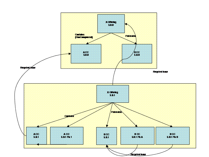
Figure 11: Fixes and updates in an aggregated
IU
Figure 11
illustrates the use of fixes and updates. An offering X, consisting
of two components A and B, is shipped at Version 5.0.0 and deployed
as a fresh install. A subsequent update to X is shipped at version
5.0.1. It contains an incremental update to both A and B, and fixes
which apply to those incremental updates.
If an
aggregating IU contains an update to a child IU, then that
aggregating IU must also be updated. However, a root IU MAY be
independently installed and it MAY be federated by multiple
aggregating IUs. Fixes and updates applied to the federated IU
outside of the context of an aggregating IU would NOT be reflected
as an update (version change) of the aggregating IU. This process,
MAY cause the dependencies of the aggregating IU to be invalidated,
if the dependencies specify a maximum version for the federated IU:
an implementation of the deployment system may warn if this is the
case. A similar situation MAY occur when a federated IU is updated
as part of an aggregated IU, and is also shared by another
aggregated IU.
Installable units are categorized as "Full" or
"Incremental". A full IU always has a unique version number, and
MAY either be a base install, which installs a new version of a
product; or an upgrade, which MAY either install a new version, or
upgrade an existing a version to a new version. The remainder
of this section considers only incremental IUs, and Full IUs that
can be applied as updates.
An
incremental update IU MAY contain only the subtrees of its original
content containing the modified SIUs. An incremental update MAY
also introduce new IUs and fixes. It MAY specify that certain IUs
have been “obsoleted” and are no longer
needed.
A full
update MAY totally replace the previous version of the installable
unit. Since a full IU MAY be installed independently of an existing
base, it MUST include all the content that is part of the required
base and that is NOT being obsoleted.
A full IU
MUST aggregate only full IUs, or full IUs plus updates and fixes to
those IUs. It MUST NOT aggregate an update or fix on its own.
However, it MAY contain fixes and updates as bundled
requisites.
An
incremental update IU MAY aggregate full IUs, update IUs and fixes.
However, for each one of the aggregated updates or fixes, the IUs
to which these are applied MUST be defined in the IUDD of the base
root IU. Each one of these updates or fixes is applied to a
corresponding IU instance within the root IU instance being
updated. In particular, the update process relies on the
restriction stated in Section 6 that an aggregate IU cannot have
two children with the same UUID, to associate each IU update to a
single instance of its required base that is located within the
corresponding aggregation level within the updated root IU, see
Section 12.5.1.
A fix is a
form of incremental update, but SHOULD only aggregate other
fixes.
Characteristics of the fix/update support
include:
·
It is possible to place
requirements on a fix at the SIU or CIU level.
·
Fixes and updates are applied
in a given context (within their aggregating IU).
·
A set of fixes for a solution
can be provided, that are to be installed together.
·
In-line IUs within a solution
cannot be updated by fixes for the same IU in another
solution.
Elements of the identity definition for
installable units are described in Section 5.1. In particular, one
of the two elements illustrated in the following diagram MAY be
specified to indicate whether the IU is an update to another base
IU. When no elements are specified, the IU is assumed by default to
be a “full” IU with no upgrade base.
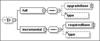
- full [anonymous type]
When specified, this element declares the IU to be a full IU, which
requires no pre-existing upgrade base to be installed. The
following elements further qualify the nature of the full
IU.
-
- upgradeBase [type=base:requiredBase]
This OPTIONAL element indicates that the full IU MAY be applied as
an upgrade to an existing base. It also defines the range of prior
versions to which this IU MAY be applied as an update. The
following elements define the version range:
-
- minVersion [type=vsn:VersionString]
This OPTIONAL element defines the minimum required
version.
- maxVersion [type=vsn:VersionString]
This OPTIONAL element defines the maximum required
version.
- type [anonymous type]
This OPTIONAL element can be use to categorize full IUs. The value
can assume one of the following enumerated values:
-
- “BaseInstall”
A deliverable that contains the initial release of a
product.
- “ManufacturingRefresh”
A deliverable that is a product replacement, containing all
previously delivered maintenance plus, optionally, new fixes not
delivered previously. This type of update may be provided as new
media, and may be packaged to install as an upgrade or as a new
install. It may apply to one or multiple products but can only
apply to one release of a product or bundle of products. It
optionally may not contain fixes previously shipped that have been
found to be in error and have not yet been fixed by available
maintenance. If it contains new function, other than any small new
function (such as a new device driver) already contained in a
previously shipped fix that is included in this Manufacturing
Refresh, then "M" in V.R.M SHOULD be incremented
- “RecommendedServiceUpgrade”
Cross product tested recommended service upgrade (RSU). A cross
product/component consolidated, tested, and recommended set of
service to a platform (or multi-platforms for distributed).
Contains all latest product/component interim fixes (distributed),
fix packs, PTFs, and refresh packs. Any previously shipped fixes
may not be included in an RSU if they have been found in error and
a correcting fix is not yet available when the RSU is built. If new
function is included in a RSU, then "M" in V.R.M SHOULD be
incremented.
- incremental [anonymous type]
When specified, this element declares the IU to be an
“incremental” update, that MAY only be applied to an
existing update base. The following elements further qualify the
nature of the full IU.
-
- updateBase [type=base:requiredBase]
This REQUIRED element defines the range of prior versions to which
this IU can be applied as an update. This element is an instance of
the same type – base:RequiredBase – discussed above for
the upgradeBase element of a full IU.
- type [anonymous type]
This OPTIONAL element can be use to categorize incremental updates.
The value can assume one of the following enumerated
values:
-
- “FixPack”
A fix pack is cumulative, i.e. contains all the fixes shipped in
previous maintenance to the release including previous fix packs.
Contains all fixes made to the original V.R.M. (i.e. 5.0.0)
delivery or to the most recent manufacturing refresh/refresh pack
(cumulative deliverable applying to one V.R.M., i.e. 5.0.1). MAY be
applied on top of any previously shipped maintenance to bring the
system up to the current fix pack level. It MAY include additional
fixes not previously shipped. It MAY span multiple products or
components.
- “RefreshPack”
Same definition as fix pack, but a refresh pack also contains new
function. The deliverable SHOULD increment the "M" of
V.R.M.
- “CriticalFixPack”
Similar to fix pack except that this deliverable consists of a
collection of selected fixes (test fixes, interim fixes, etc.)
which are usually fixes of defects with high severity.
- “DeltaFixPack”
Similar to fix pack except this deliverable is not cumulative since
GA, refresh pack, or manufacturing refresh.
- “CriticalDeltaFixPack”
Similar to a delta fix pack except that this deliverable consists
of a collection of selected fixes (test fixes, interim fixes, etc)
which are usually fixes of defects with high severity.
Elements of the identity definition for
temporary fixes are defined in Section 5.2. In particular, the
element incremental/requiredBase is an instance of
base:RequiredBase and it defines the admissible version range for
the IU to which the fix can be applied.
A
full IU can be used to create a new instance (fresh install) or to
upgrade an instance of the associated upgrade base. Therefore, the
descriptor of a full update IU can be used by the Create and the
Update operations. During the Update operation it MUST be possible
to identify IUs, including aggregates, that are already defined in
the base descriptor and that SHOULD NOT be installed as part of the
update.
A
full IU specifying an upgrade base SHOULD declare obsoleted all IUs
in the base that are not represented in the full IU
descriptor. When used as an update,
the full IU establishes a new base, i.e. the history of previous
updates applied to an existing IU instance in the upgrade base that
is not obsoleted SHOULD be ignored. The IUDD of the full IU and its
associated artifacts are used for the life cycle management of any
IU instance that is part of the updated root IU after the
update.
It
is recommended that an update descriptor use the same IUName
internal identifier for IUs that are also defined in the base
descriptor. If the same IUName internal identifier is used in an
update, it SHOULD apply to the corresponding IU in the base.
However, there is no requirement to be able to associate the IUName
internal identifier with an installed IU instance. As a result,
identification of the IU instances MUST be based on
UUID.
The
following constraint MUST be imposed on IUDD documents to support
the above identification method:
An aggregate IU CANNOT include two sibling IUs that have
the same UUID.
With
the above restriction, identification can proceed top-down from the
root IU. When corresponding aggregates have the same version no
update is required. Otherwise, for any IU definition in the current
aggregate level, the following alternatives may occur:
·
An IU found in the update
descriptor does not have a UUID match with an IU instance in the
corresponding level within the root IU instance being
updated. The IU represents new content that MUST be deployed
as part of the update, either because:
o
although defined in the base
IUDD, the IU was not selected in the base due to different feature
selections or conditions; OR
o
this is a new IU introduced in
the update IUDD.
The Create operation is performed to
create an instance of the new child IU.
·
For the IUs that have a UUID
match, the version must be compared:
o
A matching version means that
an IU was already deployed as part of the base, hence nothing needs
to be done.
o
When an instance with a
lower version is found, the corresponding IU in the update
MAY be an update (or fix) to the base instance OR it MAY be a new
base that obsoletes the current instance. An Update, or a Delete
followed by a Create is performed, depending on which one of the
above occurs.
o
An instance with an equal or
higher version may be found when this is a federated IU that
has been updated outside of the context of this aggregating IU. In
that case, no update is required.
The IU descriptor of a full update may
include CUs within aggregates that are also part of the upgrade
base, as well as CUs that belong to new aggregates. When the full
IU is applied as an update to an existing instance, it causes CU
definitions to be reset, i.e. the CUs that are associated in the
full IU to an aggregate that already exists in the base SHOULD
replace the old ones and constitute a new base for CUs in that
aggregate.
By contrast, CUs defined within an
incremental update are simply added to the ones already defined for
a corresponding aggregate of the base. An aggregate IU that is an
incremental update SHOULD NOT contain a CU with the same CUName
internal identifier of a CU defined in the corresponding base IU.
If one such CU is defined, the definition SHOULD be ignored –
it SHOULD NOT be interpreted as a definition superseding the CU
definition in the base.
The sub-set of topology targets
specified for the base root IU that are targeted by updates MUST be
defined in the topology element of the update root IU. The target
“id” attribute, see Section 5.6.1, is used to associate
targets in the update with targets in the base. The topology in the
update IU MAY include also additional targets, associated to new
features. Any IU within the update root IU that defines an update
to a base IU must be associated to the same target.
Selection requirements of a
target declared in the topology section of the base SHOULD be
omitted in the descriptor of an incremental update. If specified,
they SHOULD be ignored.
An update is deployed onto the target
instances that were selected during install of the base: a
candidate target instance that was not selected when the base IU
was deployed SHOULD not be targeted by the update. Different
implementations may have different methods to determine the range
of target instances where the base IU was installed and onto which
the update can be applied.
An updated IU – or a new IU that
is part of the update – MAY introduce new requirements to be
satisfied on a topology target. For example, a new service pack
needs to be installed on an operating system target. However, it
SHOULD be possible to satisfy the new requirements on all instances
of the target that were selected when the base instance was
created. This can be achieved for new software requirements by
specifying the canBeSatisfiedBy clause in the check.
Requirements on the target that are
introduced by a new or updated IU MAY be declared in that IU OR
they MAY be defined as additional validation requirements on
the corresponding target.
The value of a variable defined within
the descriptor of the base IU may have been passed through a
parameter map for use by actions defined in the install artifact.
The actions in the install artifact of an update IU MAY need this
information in order to implement the update in a consistent
manner. Therefore, it SHOULD be possible to access the value
of a variable defined in a previous level.
Variables defined by an IU and used
during install SHOULD retain their value across operations (see
8.4). Moreover, variables defined within multiple updates of the
same IU MUST share the same namespace:
·
a specific variable declaration – inheritedVariable –
can be used within an update to create a reference to a variable
declared in some previous level, including the base level (see
Section 8.1.6).
·
a variable name SHOULD NOT be reused in a new level other than via
inheritedVariable. The behavior is undefined if the variable name
is re-used, although some implementations MAY detect the error.
An update or fix SHOULD contain a
complete definition of its requirements.
Therefore it is expected that some
requirements would duplicate the same already expressed in the IU
descriptor of the update base. While it is a good practice to
use the same internal identifiers for checks, requirements and
alternatives that have a correspondence with the ones declared in
the update base, this is NOT required.
An update or fix MAY have more
stringent requirements on a software dependency (i.e. a
dependency associated to a software or an IU check) that was also
declared in the base IU. In that case the update MAY include
bundled requisite IUs to satisfy those requirements.
An example is as follows. An update is
required to IU “B” because of an update being applied
to another IU “A”, on which “B” depends. It
is desired to ship both updates in a single root IU, in order to
apply updates to both IUs at the same time. The synchronized update
of an IU and its dependencies can be specified as follows:
·
the check specified by IU “BUPD” (update to
B) identifies the software dependency by the same UUID (and/or
name) and a newer version;
·
a bundled requisite IU containing “AUPD”
(update to A) is specified by the canBeSatisfiedBy element
of the check.
When installing the update, the
requisite SHOULD only be applied to upgrade an instance that is
already in use by the base IU.
<iu
checkId="A_check_in_Bupdate">
<UUID>12345678901234567890123456789012</UUID>
<minVersion>8.1.1</minVersion>
<canBeSatisfiedBy>bundled_A_FixPack</canBeSatisfiedBy>
</iu>
An implementation of the Update
operation needs to ensure that, in presence of software
dependencies declared in multiple alternatives of a requirement,
the same instance of an external software dependency is selected
that is already in use by the base. See Section 7.2 for a
definition of requirements with alternatives.
To facilitate this, the following
assertion is made:
One IU MUST NOT have a dependency on
more than one IU instance with a given UUID or name.
If an IU update declares a software
dependency to an IU with the same UUID (or name) as a dependency
already satisfied in the base, the same instance already in use
SHOULD be selected. Because of the above assumptions, the following
process can be applied to the evaluation of alternatives for
each requirement declared in the IU update:
·
Software dependencies that are in use by the IU instance being
updated are identified;
·
Any software dependency within an alternative that matches a
dependency already in use – by UUID or name, not necessarily
version – is restricted to be satisfied by the same instance,
possibly after applying an update if the corresponding check
specifies a newer level – or temporary fixes – and a
bundled requisite. See Section 11.4 below;
·
If a software dependency in a selected alternative in the
base appears in more than one alternative in an update, then this
needs to be resolved to one alternative in the update. This
resolution MAY be performed automatically, based on criteria such
as the number of satisfied dependencies in the alternative, or
priority. The resolution MAY also be made by an external decision,
e.g. by a user selection.
One application requires one database
for its internal use and another one for customer data, and there
are separate requirements for each one: the customer data could be
on database IUs “dbXX” or “dbYY”, while the
private application data should be on “dbZZ” or
“dbXX”. When the application is first created,
“dbXX” is selected for both customer data and for
private data (e.g. because “dbYY” and
“dbZZ” were not available or were lower priority
alternatives). Where the two requirements are declared in the same
IU, the rule stated in the previous section prevents the
application to be installed having the same CIU or SIU dependent on
two different instances of “dbXX”. Therefore it can
assumed that in this case the base IU instance will have two
software dependencies satisfied by the same instance of
“dbXX”.
The following XML fragments illustrates
how the requirements may be defined in the base IU:
<requirements>
<requirement name="customer_data_database"
operations="Create">
<alternative name="dbXX_found" priority="2">
<checkItem checkIdRef="db2_check"/>
</alternative>
<alternative name="dbYY_found" priority="1">
<checkItem checkIdRef="oracle_check"/>
</alternative>
</requirement>
<requirement name="private_data_database"
operations="Create">
<alternative name="dbZZ_found" priority="2">
<checkItem checkIdRef="db2_check"/>
</alternative>
<alternative name="dbXX_found" priority="1">
<checkItem checkIdRef="oracle_check"/>
</alternative>
</requirement>
</requirements>
An update for the above IU could
specify the same requirements for the above databases, apart from a
new update level that is required on “dbXX”. At the
time when the update is applied, “dbZZ” is found to
exist in the system and that is the preferred choice for the
application private data. However, the process illustrated in the
previous section will still select the “dbXX”
alternative on both requirements, because there is one instance of
“dbXX” already in use by the required base.
As explained in Section 9.1 for the
supersededFixes element of an IU definition, updates and
fixes MUST be able to handle superseded fixes. However, nothing can
be assumed about the compatibility of an update or a temporary fix
with fixes that are already applied to the IU instance being
updated, when
·
these fixes are NOT listed as being superseded by the update or
fix; e.g. because these fixes were released after the update
was manufactured
·
fixes already applied are NOT listed among fix dependencies, see
Section 9.2.1, of a new fix that is being applied.
The following SHOULD apply to fixes
identified by the above conditions:
·
A fix “B” MAY be applied without rolling-back an
applied fix “A” that is not superseded by
“B”. However, “B” SHOULD NOT be applied if
“A” supersedes “B”.
·
When installing an update, full or incremental, all fixes that are
NOT listed as superseded by the IU SHOULD be rolled back before
processing the update.
·
In the previous situation, if there are fixes NOT superseded by the
update that cannot be rolled back, the update SHOULD NOT be
installed. A new level update will be required, that includes the
installed fix among superseded fixes, OR that declares updated fix
dependency information.
A federated IU may be defined in an
update with the intent to apply maintenance to an IU instance
federated by the base IU. The following conditions MUST be met for
the update to be possible:
·
The federated IU definition appears in the update descriptor in the
same relative location with respect to the root IU where the
corresponding federated IU appears in the base.
·
for each alternative in the base federated IU definition that
requires an update, there is an alternative in the update
definition whose IU check specifies the same UUID; see Section 6.3
for a definition of federated IUs;
·
the canBeSatisfiedBy element of each IU check in the federated IU
definition refers to a bundled requisite that can be installed as
an update on top of the corresponding IU in the base
declaration.
Updates and fixes applied to a root IU
instance may introduce new configuration units, which are processed
initially during the Migrate process. See Section 4.3. After the
Update is applied, CUs associated to obsoleted IUs and superseded
fixes are not applicable any more. However, when a Configure
operation is re-applied in full mode, see Section 4.2.5, to
an IU instance that was subject to one or more incremental updates
or fixes, all the configuration units defined in the IU descriptor
of the base and the ones defined in the IU descriptors of the
updates/fixes are re-applied.
The order in which CUs are applied is
determined by depth-first rule and sequence numbers, as discussed
in Section 12. As an example, a CU defined with the highest
sequence number in a top-level IU will be the last to be applied
within that context.
All CU definitions introduced by an
incremental update are intended to be incremental. In order to cope
with the problem of CUs possibly causing undesired effects, an
implementation MAY support selecting CUs that should not be applied
during the InitialConfig, Migrate and Configure operations.
As explained in see Section 11.1,
applying a full IU update to an existing base has the effect of
establishing a new base for configuration units, thus effectively
replacing any CUs associated to a non obsoleted IU instance.
The following guidelines illustrate the
expected order of evaluation for targets, dependencies and
variables. The guidelines are intended to facilitate a consistent
interpretation of IUDDs by different management applications.
This section also defines how to determine the
order of installation of IUs.
Variables MAY be evaluated on-demand.
Variables MUST be evaluated before they are used.
The return from a query MAY be affected
by the installation of other IUs. The “nominal” value
of a query is its value when the query is performed immediately
before the installation of the IU in which it is defined: a query
SHOULD NOT be evaluated prior to this point, although it MAY be
evaluated any time before first use. To avoid unexpected
differences in behavior, its value SHOULD NOT be modified by any
installation actions before its first use. Once evaluated,
the value of a query SHOULD NOT be re-evaluated.
Variables that are NOT used, e.g.
because they are used inside a condition which evalutes to
“false”, MAY NOT be evaluated.
The candidates for a given logical
target SHOULD satisfy all of the selection dependencies
specified in the root IU and in all referenced IUs, recursively,
that have a target map for that target. The members of the resolved
target list SHOULD satisfy all of the selection and validation
dependencies in the root IU and in all referenced IUs, recursively,
that have a target map for that target. See Section 5.6.1.
Targets SHOULD only be evaluated if they
correspond to hosting environments for selected IUs, to the targets
of checks for selected IUs; OR to resources whose existence is
required by required relationships of other targets.
Custom checks SHOULD NOT be used in
topology requirements, because to evaluate them would typically
require installation and execution of code on the candidate
targets, and an implementation is not REQUIRED to support this. If
an implementation does support this, then variable expressions
involving variables based on queries SHOULD NOT be used within the
custom check, as the queries may be against targets that have not
yet been resolved.
Evaluation of IU checks and software
checks SHOULD take into account the list of IUs that are selected
for install, as well as the list of IUs that are already
installed.
All of the requirements on child IUs and
referenced IUs SHOULD be evaluated before installing a given
IU.
Order of installation is defined to be depth-first. The
schema supports specifying a sequence number on installable units
and configuration units. This sequence number can be used to
control ordering of immediate children within a parent: child IUs
are ordered by increasing sequence number. If an explicit sequence
number is not specified, the IU MUST be installed after any IU with
a specified sequence number. Where two siblings have the same
sequence number, the dependency checker MAY choose to order them as
best meets any dependencies, or can install them in
parallel.
For
the top level of IUs and CUs in a root IU, the sequence numbers
span both required content and selectable content. Sequence numbers
associated to configuration units are processed during the
Configure operation.
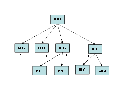
Figure 12: Sequencing of install
In
the above example, one possible order for completion of install
would be: IUG, IUD, IUE, IUF, IUC, IUB. During configuration, the
order of configuration would be: CU3, CU1, CU2. Note that IUB
completes install after all of its children, although it
effectively starts its install prior to its first child
(IUD).
The
use of sequence numbers is primarily intended for situations where
the aggregate consists of a set of tightly coupled inline IUs,
where the details of actual dependencies may not be fully
understood or may be very numerous. For relatively loosely coupled
IUs, the preferred mechanism is to specify internal dependencies
within the root IU. In particular, if there are dependencies
between different selectable content IUs, these should be expressed
using IU checks, because this will allow checking of the
consistency of selections and the order of install. However, note
that the existence of an internal dependency between the IUs does
not cause the implicit selection of a feature containing dependent
IUs.
These internal dependencies should be expressed using an IU
Check, specifying the internal IU name of the IU that must be
installed first, see Section 7.3.6.
The
presence of a dependency between two installable units MUST be
consistent with the sequencing of their install as determined by
their position in the aggregate tree and, if siblings, by their
sequence numbers.
An
IU “Y” – base install, update or fix – MAY
have a pre-requisite (default) or requisite dependency on another
IU “X”. That dependency is expressed by an IU check or
by a software check. A pre-requisite dependency must be satisfied
before install, while a requisite dependency must be satisfied
before install is completed. This information may be used by the
install runtime in determining the appropriate install order, not
only within a root IU, but also between requisites and
prerequisites.
The
lifecycle operations for an installable unit are described in
Section 4.2. This section describes how these lifecycle operations
apply to aggregated IUs.
When
performing a change management operation on an aggregated IU, the
lifecycle operation for each child IU will depend on:
·
The lifecycle operation being
performed by the root IU.
·
Whether the child IU already
exists.
·
The existence of any
prerequisite dependencies.
In
particular, a pre-requisite IU “X” that is being
created (new instance) MUST be in the Usable state, thus requiring
the Create and InitialConfigure operations to be applied, before a
dependent IU “Y” can be installed. Analogously, a
pre-requisite IU “X” that is being updated MUST be in
the Usable state, thus requiring the Update and Migrate operations
to be applied, before a dependent IU “Y” can be
installed.
For
example, consider the update A’ illustrated in the following
figure.
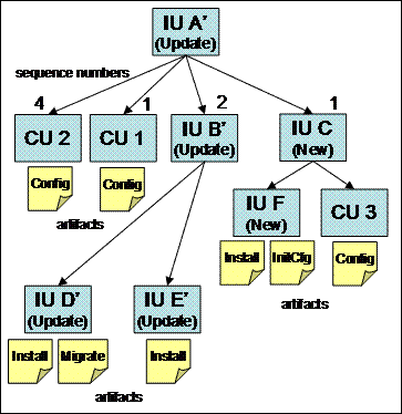
Figure 13:
Update with new content
In
this case all IUs are updates other than IUC and IUF, which are new
IUs. This IU can be installed in the context of an Update operation
to an existing instance of IU A, the required base onto which IU
A’ can be applied. Installing this IU will cause the Update
lifecycle operation on IUA, IUB, IUD and IUE; and a Create
lifecycle operation on IUC and IUF.
The
following principles determine the sequence of operations when
installing an update:
·
each IU instance to which an
update/fix is applied MUST be in the Usable state;
·
both new and updated IU
instances SHOULD be left in the Usable state at the end of the
update process (error conditions are NOT discussed
here).
If
there are no pre-requisite relationships specified between
resources, a lifecycle operation on an aggregated IU will cause its
child IUs to perform the same lifecycle operation. In this case,
all of the IUs will be brought to the “Created” or
“Updated” state, and then to the “Usable”
state. The initial creation or update lifecycle operations are
initiated from the child IUs according to the sequencing rules
described in the previous section. The sequence of lifecycle
operations for the above example will be (IU state changes listed
at each step between square brackets):
1.
IUF.Create
[IUF Created, IUC
Created]
2.
IUD.Update
[IUD Updated]
3.
IUE.Update[IUE.Usable, IUB Updated]
4.
IUF.InitialConfig[F Usable]
5.
IUD.Migrate [IUD Usable, B Usable]
6.
CU3.Configure
[IUC Usable]
7.
CU1.Configure
8.
CU2.Configure
[IUA Usable]
In
the above sequence, step 4 does NOT cause IUC to become Usable,
because there is a new configuration unit that needs to be applied.
As explained in Section 4.3, configuration units define the
repeatable part of the initial configuration, and the
new CUs introduced by the update are automatically applied at the
end of the update process. This
is represented by steps 6-8 in the above sequence.
When
there are pre-requisite relationships, the prerequisite IU must be
in the “Usable” state before a dependent IU can be
installed. As an example, let assume that a pre-requisite
dependency exists between IUE and IUD. This means that IUD must be
fully configured before IUC can be installed. Steps 1-5 in the
above sequence would change as follows:
1.
IUF.Create
[IUF Created, IUC
Created]
2.
IUD.Update
[IUD Updated]
3.
IUD.Migrate[IUD Usable]
4.
IUE.Update[IUE.Usable, IUB Usable]
5.
IUF.InitialConfig[F Usable]
The diagram in Figure 14 illustrates in
more detail the case of an aggregate (IU A’) including
updates (E’, F’ and F”) to installable units (E
and F) within the base IU A.
In
this example, the dashed boxes represent a target IU that is being
updated when the aggregate update A’ is installed on an
existing instance of A.
Multiple incremental updates to the same base can be
chained together, as shown in the example for F, F’ and
F”. In this example, F” is applied to the instance that
is created by applying F’ to F. As a general rule, the
presence of a sibling update X’ satisfying the required base
definition for an update X” is always restricted to apply to
the same instance of X which X’ is applied to. This is
consistent with the general rule stated in Section 6 that an
IU aggregate cannot have two
children with the same UUID.
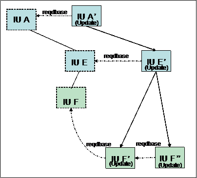
Figure 14: Multiple
updates within the same aggregate
The
following general applies to the update process:
The required base specified in update and fix definitions
MUST be treated as a pre-requisite type of
dependency.
A pre-requisite type of dependency implies that the
required resource MUST be in the Usable state before a dependent IU
can be installed.
In
the above example, F” has a pre-requisite dependency on
F’. As a consequence, update and migrate operations (if
migration is required) are required to bring F’ to the Usable
state before F” can be installed.
A
slightly different example is one where the aggregate E is a
new IU, itself part of the update. In that case, F should be
installed and initially configured before F’ can be
applied.
The
case in which E and F are IU aggregates containing configuration
units can be treated similarly because of the general rule stated
in Section 4.3, namely that it SHOULD be possible to apply
configuration units after all InitConfig and Migrate
artifacts for the whole root IU have been processed. In the above
example: it would be possible to install F” on top of the
updated instance where F’ has been installed, that is after
the F’ Install and Migrate artifacts have been processed, but
before any configuration unit that MAY be contained in F’ are
applied.
The diagram shown in Figure 15
illustrates the case in which F is a federated IU in the base
aggregate (E). In that case, also the updated aggregate (E’)
specifies the new required level of the IU (F’) as a
federated IU. In this case, the new desired level of the
federatedIU for the update is identified by the IU checks in the
federated IU definition.
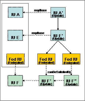
Figure 15: Bundling
updates to a federated IU
In
order to ship updates to a federated IU within the same update
aggregate, the IU check defining the federated IU must
contain the canBeSatisfiedBy declaration pointing to a
bundled requisite, see Section 7.3.6 for a definition of IU
checks.
The
following logic SHOULD be applied to deploy bundled updates to an
IU instance federated by the base root IU.
·
Federated IU instances are
located within an aggregation level of the base root IU,
corresponding to the one where the updated federated IU definition
is located. In the above example, in order to target the
federated IU update F’, federated instances associated to the
E aggregate will be located.
·
The IU check specifed in the
update MAY be already satisfied in case the federated IU F has been
independently updated, e.g. as part of another root IU in which it
is contained. In that case, there is no need to apply any
update.
·
Where there is one partial
match (UUID and name only) and there is a bundled update
(canBeSatisfiedBy element in the IU check), the update is
applied to the instance, after positive checking that the required
base declaration in the bundled update are satisfied by that
instance. In the above example: the required base declaration in
the bundled update F’ is verified against the federated IU
instance F in E. A single matching instance SHOULD be found,
consistently with the general rule stated in Section 6 that
an IU aggregate cannot
have two children with the same UUID.
·
Multiple incremental updates to
the same federated IU can be also chained together. In the above
example, the bundled updates F’ and F” can be applied
in sequence to F. As a general rule, the presence within an update
(E’) of sibling federated IUs F” and F’ whose IU
checks have matching identity is interpreted as the intent to apply
the corresponding bundled requisites (F” and F’) to the
same instance (F). The order in which the bundled updates are
applied is determined by the required-base declarations in their
descriptors. Similarly to the case discussed in Section 12.5.1, the
required base MUST be usable before the update can be
applied.
Installable unit instances may be identified
by their identity fields (UUID, version, name). Therefore,
the IU identity should be considered as the primary signature of an
installable unit. However, an IU instance could also be
detected by the presence of specific signatures (files, registry
entries, etc.). IU developers are the most reliable source of
accurate signature information for an IU, so there is an advantage
to have this information readily available from the IU descriptor,
instead of having to create this information a-posteriori.
The signature information provided within an
IU definition serves the following purposes:
- A third party Inventory or License Management
application that does not rely on the installable unit registry MAY
use the IUDD as a reliable source of signatures.
- Tools to provide a signature software catalog
for consumption by third party applications or by the installation
runtime can assemble signatures from multiple descriptors.
- An IU descriptor could be defined for a
software component that is also distributed as a legacy package.
The installation runtime may use a signature software catalog to
discover instances that are not known to the runtime, for example
because they were not installed as an IU via the runtime.
A hosting environment MAY use the IU name, see
Section 5.1, and detect an IU instance by the presence of a
matching entry in a platform registry, e.g. an operating system
registry of installed software products. When the signature
information is available, using a specified signature SHOULD be
considered the preferred method for reliably detecting an
instance.
The signatures element is an OPTIONAL
element of an IU Definition, see Section 9.1. This element includes
an unbounded sequence of signature elements whose type
– sigt:Signature – is abstract. This abstract type
defines only one OPTIONAL attribute that is common to
all signatures:
- keySignature
[type=boolean]
A value of “true” – this is the default –
indicates that the presence of the signature is a necessary
condition for an instance of the IU to be considered installed.
Specifying more than one signature element with this attribute as
“true” implies that all of them must be detected for
the IU to be considered installed.
When this attribute is specified with a value of
“false” the signature indicate an additional element,
e.g. a file, whose existence MAY be checked for other purposes,
e.g. license management or integrity checking.
Being an instance of an abstract type, each
signature element MUST specify a concrete derived type. Different
signature types MAY be appropriate on different hosting
environments, and could be defined by one or more concrete
signature types derived from sigt:Signature. The following
signature types are defined for support on an operating system
hosting environment:
·
FileSignature [type=sigt:FileSignature]
·
WindowsRegistrySignature [type=sigt:WindowsRegistrySignature]
·
OsRegistrySignature [type=sigt:OsRegistrySignature]
The type sigt:FileSignature is illustrated in
the following diagram.
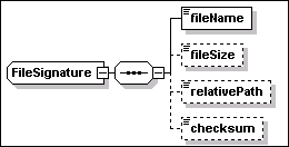
File signatures have the following
attributes, in addition to the keySignature attribute
inherited from the base abstract type:
·
platform [type=sigt:PlatformType]
This OPTIONAL attribute is used to specify the operating system
platform. Different characteristics may need to be specified
for a file on different platforms. This attribute restricts the use
of the associated file signature to a specific platform. The type
of this attribute is defined as a union of the XML type QName and
rtype:OS_RT. Therefore, a user defined operating system type MAY be
specified as a QName value. Standard enumerated values for the
operating system are defined in rtype:OS_RT.
- keyExecutable
[type=boolean]
This OPTIONAL attribute is used to identify a file as a key
executable of the application for license management purposes.
File signatures have the following
elements:
·
fileName [type=string]
This element is REQUIRED. It specifies the name of the file.
·
fileSize [type=nonNegativeInteger]
This element is OPTIONAL. It specifies the size of the file in
bytes. The size of the signature file is not a mandatory element of
the signature, because there MAY be products whose key files are
actually built during install using object-code and libraries
available in the underlying hosting environment and whose size
cannot be pre-determined in advance. In this case, one SHOULD
specify multiple key files in order to increase the reliability of
a matching based only on file names.
·
relativePath [type=base:RelativePath]
This element is OPTIONAL. It is used to specify the file location
with respect to the installable unit’s install location. When
this attribute is specified it is possible to compare the file
actual location with the relative path and determine the IU install
location. The value “.” indicates that the file is
located immediately below the install location directory.
·
checksum [type=base:CheckSum]
This element is OPTIONAL. If specified, the value can be used to
verify the file integrity or to improve the safety of matching. The
element defines the digest of the file in a string format. The
content can be interpreted knowing the hash algorithm type used to
compute the digest. The algorithm is specified by the following
attribute
o
type [anonymous type]
This attribute is OPTIONAL. The default, if the checksum is
specified without a type, is “CRC32”. The decimal
representation is used for a CRC32 checksum. Other possible
enumerated values are:
§
“MD2”
§
“MD5”
§
“SHA-1”
§
“SHA-256”
§
“SHA-584”
§
“SHA-512”
<signature xsi:type="sig:FileSignature"
keySignature="true"
platform="OSCT:Windows">
<fileName>myAppLibrary.dll</fileName>
<fileSize>123456789</fileSize>
<relativePath>lib</relativePath>
<checksum type="CRC32">4010203041</checksum>
</signature>
<signature
xsi:type="sig:FileSignature" keySignature="true"
platform="OSCT:Linux">
<fileName>myAppLibrary.so</fileName>
<fileSize>121111111</fileSize>
<relativePath>lib</relativePath>
<checksum type="CRC32">4010203042</checksum>
</signature>
<signature xsi:type="sig:FileSignature"
keySignature="false"
platform="OSCT:Windows" keyExecutable="true">
<fileName>myAppExecutable.exe</fileName>
<fileSize>234567890</fileSize>
<relativePath>bin</relativePath>
<checksum type="CRC32">4010203043</checksum>
</signature>
<signature xsi:type="sig:FileSignature"
keySignature="false"
platform="OSCT:Linux" keyExecutable="true">
<fileName>myAppExecutable</fileName>
<fileSize>234567890</fileSize>
<relativePath>bin</relativePath>
<checksum type="CRC32">4010203044</checksum>
</signature>
The above example illustrates the
elements and attributes of a file signature. In particular, a
scanner detecting a match for the key file in the first signature
with the
“C:\MyCompany\MyApplication\lib\myAppLibrary.dll”
file, can determine that the file belongs to an instance of that
IU. The scanner would be also able to determine, based on the
signature relativePath declaration, that
“C:\MyCompany\MyApplication” is the IU instance install
location.
The type sigt:WindowsRegistrySignature
is illustrated in the following diagram.
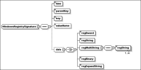
This type of signature detects entries
in the registry of a Microsoft Windows operating system. The only
attribute of this type – keySignature – is inherited
from the base type sigt:Signature.
The elements are all instances of the
string type and define a key to be found in the Windows registry:
·
hive
[type = sigt:WinRegHive]
This element is REQUIRED. It is used to specify the name of the
hive to which the signature key belongs. One of the following
enumerated values MUST be specified
o
“HKEY_CLASSES_ROOT”
o
“HKEY_CURRENT_USER”
o
“HKEY_LOCAL_MACHINE”
o
“HKEY_USERS”
o
“HKEY_CURRENT_CONFIG”
·
parentKey [type=string]
This REQUIRED element is used to specify the parent key of the
signature key.
·
key [type=string]
This REQUIRED element is used to specify a key whose existence is
part of the signature.
·
valueName
[type=string]
This OPTIONAL element is used to specify the name of the entry. If
omitted, the signature is assumed to refer to the default
entry.
·
data [anonymous type]
This elements is
used to specify the value data content. The element MUST be
specified if the valueName element is specified. Content is
specified by one of the following nested data elements:
o
regDword [type=int]
o
regString [type=string]
o
regMultistring
This is a sequence of one or more of
the following elements.
§
regString [type=string]
o
regBinary [type=hexBinary]
o
regExpandString [type=string]
The following XML fragments illustrate
Windows registry signatures.
<signature
xsi:type="sig:WindowsRegistrySignature" keySignature="true">
<hive>HKEY_LOCAL_MACHINE</hive>
<parentKey>SOFTWARE</parentKey>
<key>Adobe/Acrobat Reader/5.0</key>
</signature>
<signature
xsi:type="sig:WindowsRegistrySignature" keySignature="true">
<hive>HKEY_LOCAL_MACHINE</hive>
<parentKey>SOFTWARE</parentKey>
<key>IBM/GSK4/CurrentVersion</key>
<valueName>Version</valueName>
<data>
<regString>4.0.2.49</regString>
</data>
</signature>
This type is similar in structure to the
Windows Registry signature type. However the intent is to be able
to define the registry information for generic operating system
registries. The primary use of this registry based signature is to
be able to identify installed legacy software without having to
perform a full file-system scan, which can take a considerable
amount of time.
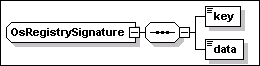
OS generic registry signatures have the
following attribute, in addition to the keySignature
attribute inherited from the base abstract type:
·
platform [type=sigt:PlatformType]
This OPTIONAL attribute is used to specify the operating system
platform. See Section 13.1 above, for a description of the
same attribute in a file signature.
The
elements are all instances of the XML string type.
The following list includes, for the specified operating systems,
the platform type (between square brackets), the source of this
information (e.g. “rpm” on Linux) and the names of the
supported key values:
·
IBM AIX [OSRT:IBMAIX] (lslpp)
o
FileSet
o
Description
·
SUN Solaris [OSRT:SunSolaris]
(pkginfo)
o
NAME
o
PKGINST
·
HP HPUX [
OSRT:HPUX] (swlist)
o
tag
o
product
·
Linux [
OSRT:Linux] (rpm)
o
package_name
o
NAME
<signature
xsi:type="sig:OsRegistrySignature" keySignature="true"
platform="OSRT:Linux">
<key>package_name</key>
<data>abiword-2.0.99.0.20031031-1.i386</data>
</signature>
13.4 Signature
definitions in a temporary fix
A temporary fix MAY include a
declaration of signatures for the following purposes:
·
Applying the fix MAY cause a signature (e.g. a file signature) that
had been declared for the fixed IU to become out of date. A
software scanner using the original signature would fail to detect
an IU instance after the fix has been applied. A signature declared
in the temporary fix definition that provides updated values for a
corresponding signature item (file, registry entry, etc.) in the
fixed IU can be used to detect both the base IU and the fix.
·
A temporary fix that does not modify any key signature of the base
IU MAY define one or more signatures for itself, by which a
software scanner could detect the presence of the fix. In case of a
file signature, the scanner MAY be able to determine the install
location of the IU to which the fix has been applied.
This section proposes a standard
format for an artifact containing action definitions. A standard
format has advantages in terms of consistency and potential reuse
across different hosting environments, both of the artifacts
defined using the standard format, and of the implementation code
that processes the artifacts and implements the action. Further,
for certain categories of hosting environment (e.g. operating
system, J2EE, RDBMS), it is proposed that a set of standard actions
should be defined. These actions will differ by hosting
environment category. It is also expected that there will be
additional actions that are either specific to a particular
product, or that are provided by different install product vendors,
and so it is recommended that an implementation support the
pluggability of different action sets.
The schema for the action definition
format – action.xsd, see Appendix L – is independent
from the main schema files. A complete schema for actions supported
by a hosting environment, e.g. the operating system, would be
provided as a further schema file. This would provide concrete
types for each of the abstract schema types defined in
action.xsd.
The content of an action definition
artifact is a single element, of type action:Artifact. The content
of this element is illustrated below:
An Artifact may contain a set of
Variables, see Section 14.1 and BuiltInVariables, see
Section 0. The other elements of an Artifact are as
follows.
|
Element
|
Description/Use
|
|
artifactType
|
type = base:ArtifactType –
use=optional
The artifact type is one of:
Install, InitialConfig, Update, Migrate, VerifyInstall, Uninstall,
Configure, VerifyConfig, and CustomCheck. It defaults to
Install.
The artifact type is used to
determine how to process the artifact. For example, an Install
artifact may be used to uninstall an IU, by undoing each of the
actions in the definition. It may also be used to verify an IU, by
checking that the relevant actions have been applied.
|
|
hostingEnv
|
type=siu:AnyResourceType –
use=optional
This element specifies the type of
hosting environment to which the artifact can be applied.
|
|
artifactSchemaVersion
|
Type=vsn:VersionString
This element specifies the version
of the schema, which is fixed.
|
|
requiredActionSet
|
Type=action:RequiredActionSet
– use=optional
This element specifies an action set
from which the actions in this artifact derive. See Section
14.3.
|
|
actionGroup
|
Type=action:UnitActionGroup
(abstract)
This element specifies a set of
actions to be performed, see Section 14.4
|
Variables of the following types can be defined within
artifacts:
·
parameter
·
derivedVariable
·
result (no
variable content is specified in its definition).
The
first two are as described in Section 8.1.1 and in Section 8.1.2,
respectively. The result type is used to hold the result of an
action, which can then be used in subsequent actions.
Variables
defined within an artifact cannot be used to modify variables
defined in the IUDD where the artifact is referenced, or in a
different artifact.
In actions that consume variable values, the action
definition must provide a means to specify how these variables are
used within the action. Similarly, in actions that provide result
variables, the action definition must provide a means to specify
how variables can be set from the action
results.
Built-in variable types may be defined for a given hosting
environment action set. These variable types allow the definition
of a variable instance in an artifact that takes a value returned
from a “function like” expression, to be
evaluated by the hosting environment.
The
builtInVariables element defines an OPTIONAL set of
variables of abstract type BuiltInVariable. Each variable
has a required name attribute of type NCName.
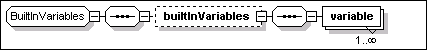
Concrete derived types for a buil-in variable need to be
defined for each hosting environment.
The following schema fragment
illustrates how a concrete built-in variable may be
defined.
<complexType
name="OsBuiltInVariable">
<complexContent>
<extension base="action:BuiltInVariable">
<choice>
<element name="systemVariableValue">
<complexType>
<attribute name="sysVarName"
type="base:VariableExpression"/>
</complexType>
</element>
…
</extension>
</complexContent>
</complexType>
The schema defines
OSBuiltInVariable, which extends
action:BuiltInVariable.
The semantic of the built-in variable
is to return the value of the specified system environment
variable. The following XML fragment illustrates how the above
built-in variable may be used.
<builtInVariables>
<variable
xsi:type="osac:OsBuiltInVariable"
name="ProgramFilesDir">
<systemVariableValue sysVarName="ProgramFiles" />
</variable>
</builtInVariables>
As illustrated in the above example,
the non abstract type of the action group must be specified for the
unit element via the xsi:type attribute. In this example, the
variable is chosen to be an instance of osac:OsBuiltInVariable. The
example defines a variable named ProgramFilesDir, which is set to
the value of the ProgramFiles system variable.
The requiredActionSet element of
the artifact supports pluggability of action sets for any hosting
environment. The requiredActionSet may be used to declare
the action sets that are required by a specific artifact, for the
artifact to be deployable. An implementation MAY perform a check to
determine if the artifact can be handled by a hosting environment,
before invoking the associated change management operation to apply
the artifact to the hosting environment.
Two action sets may 'overlap' and define
a common subset of actions. Therefore, in order to unambiguously
associate an action to a definition of the required action set
implementation, all action instances derived from
action:BaseAction contain a reference to the implementing
action set through the actionSetIdRef attribute.
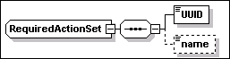
The elements of the
RequiredActionSet are defined in the following table:
|
Element
|
Description/Use
|
|
UUID
|
type = base:UUID
– use=required
This element is
a globally unique UUID that identifies the action set.
|
|
name
|
type=token– use=optional
This element is
used to specify the name of the action set.
|
|
Attribute
|
Description/Use
|
|
actionSetId
|
Type=ID –
use=required
This attribute
is used to associate an action in the artifact to a defined action
set.
|
An action artifact MAY include multiple
action groups. Each group is a container for actions that is
controlled by a condition. The element actionGroup is an instance
of the abstract type action:UnitActionGroup. This type only defines
the following condition attribute:
|
Attribute
|
Description/Use
|
|
condition
|
type =
base:ConditionalExpression – use=optional –
default=”true”
This attribute,
inherited from the base type, is used to specify a conditional
expression. The action group is ignored when the result that is
obtained by evaluating the condition is
“false”.
|
All actions defined in an artifact
SHOULD be derived from the base type action:baseAction.

The following attributes are
inherited by all actions:
|
Attribute
|
Description/Use
|
|
Condition
|
type =
base:ConditionalExpression – use=optional –
default=”true”
This attribute
is used to specify a conditional expression. The action is ignored
when the result that is obtained by evaluating the condition is
“false”.
|
|
actionSetIdRef
|
type=NCName
– use=optional
This optional
attribute is used to qualify the action set from which this action
is derived. If it is not specified, a hosting-environment specific
mechanism for resolving the appropriate action set MAY be applied.
This mechanism SHOULD by default select actions from the standard
set defined for the hosting environment.
|
The following element is
inherited by all actions:
|
Element
|
Description/Use
|
|
displayName
|
type=base:DisplayElement –
optional
Description of
the action. Example of usage: the short_default_text element for
the current locale may be used as a label of the corresponding
object in an IDE GUI.
See Section 17
for a general description of display elements and their
localization.
|
The following schema fragment
illustrates how a concrete action set may be defined.
<complexType
name="OsActionGroup">
<complexContent>
<extension base="action:UnitActionGroup">
<sequence>
<element name="actions">
<complexType>
<choice maxOccurs="unbounded">
<group ref="osac:OsActionChoice" />
</choice>
</complexType>
</element>
</sequence>
</extension>
</complexContent>
</complexType>
A type is defined which extends the
UnitActionGroup abstract type. It specifies that an
OSActionGroup contains a set of actions defined in
OSActionChoice.
<complexType
name="OsActionChoice">
<choice
maxOccurs="unbounded">
<element name="addDirectory"
type="osac:AddDirectoryAction"/>
…
</choice>
</complexType>
<complexType
name="AddDirectoryAction">
<complexContent>
<extension base="action:BaseAction">
<sequence>
<element name="directory"
type="command:DirectoryDefinition"/>
</sequence>
</extension>
</complexContent>
</complexType>
AddDirectoryAction is one of the
actions defined in OSActionChoice. This action extends the
action:BaseAction abstract type. It contains a definition of
the directory to be added.
The following XML document illustrates
what an artifact conforming to the SI action definition format may
look like.
<?xml version="1.0"
encoding="UTF-8"?>
<action:artifact
xmlns:action="http://www.ibm.com/namespaces/autonomic/solutioninstall/action"
xmlns:OSRT="http://www.ibm.com/namespaces/autonomic/OS_RT"
xmlns:osac="http://www.ibm.com/namespaces/autonomic/solutioninstall/OsActions"
xmlns:xsi="http://www.w3.org/2001/XMLSchema-instance"
xsi:schemaLocation="http://www.ibm.com/namespaces/autonomic/solutioninstall/OsActions
osActions.xsd">
The
namespace of the concrete action definition schema (osac) and the
namespace for the relevant resource types are defined.
<artifactType>Install</artifactType>
This is an Install artifact. It may be used to drive the
following IU lifecycle operations: Create, VerifyIU, Delete,
Repair.
<artifactSchemaVersion>1.2.0</artifactSchemaVersion>
<requiredActionSet
actionSetId="osIBMBase">
<UUID>12345678901234567890123456789012</UUID>
<name>com.ibm.solutioninstall.ostp.BaseActionSet</name>
</requiredActionSet>
Information is provided to allow implementations to
identify the action set from which the actions derive.
<actionGroup xsi:type="osac:OsActionGroup">
<actions>
…
<addDirectory actionSetIdRef="osIBMBase">
<directory create="true" delta_compressed="true">
<location>/usr/local</location>
<name>MyProduct</name>
<source
descend_dirs="true">
<source_archive format="jar">
<fileIdRef>file_00097</fileIdRef>
</source_archive>
</source>
<directory create="true">
<name>Docs</name>
<file>
<name>Readme.First</name>
<source>
<fileIdRef>file_0099</fileIdRef>
</source>
</file>
</directory>
</directory>
</addDirectory>
</actions>
</actionGroup>
</action:artifact>
As illustrated in the above example,
the non abstract type of the action group must be specified for the
unit element via the xsi:type attribute. In this
example, the group is chosen to be an instance of
osac:OsActionGroup.
The format
of the resource properties definition artifact is shown below. This
artifact format SHOULD be supported for both Config and
VerifyConfig operations. Other artifact formats MAY be
supported.
<?xml
version="1.0" encoding="UTF-8"?>
<schema
xmlns="http://www.w3.org/2001/XMLSchema"
targetNamespace="http://www.ibm.com/namespaces/autonomic/solutioninstall/config"
xmlns:config="http://www.ibm.com/namespaces/autonomic/solutioninstall/config">
<element name="configArtifact"
type="config:ConfigArtifact"></element>
<complexType
name="ConfigArtifact">
<sequence>
<element name="propertyValues">
<complexType>
<sequence>
<any maxOccurs="unbounded" minOccurs="0"
processContents="skip" namespace="##any"></any>
</sequence>
</complexType>
</element>
</sequence>
</complexType>
</schema>
The resource properties definition artifact
consists of an outermost delimiting element –
propertyValues – followed by an unbounded sequence of
any element. The elements MUST correspond to properties exposed by
the target resource, with the element values specifying the values
that are to be set or verified.
For example, a resource properties definition
artifact might contain the following:
<?xml
version="1.0" encoding="UTF-8"?>
<config:configArtifact
xmlns:config="http://www.ibm.com/namespaces/autonomic/solutioninstall/config"
xmlns:xsi="http://www.w3.org/2001/XMLSchema-instance"
xsi:schemaLocation="http://www.ibm.com/namespaces/autonomic/solutioninstall/config
config.xsd ">
<propertyValues>
<NumberOfLicensedUsers>5</NumberOfLicensedUsers>
</propertyValues>
</config:configArtifact>
This would set the number of licensed users to
5, or validate this value. Multiple property values MAY be
specified, and these properties MAY be structured.
For properties which may have multiple
instances, if any instance of that property is specified,
all instances of that property are replaced with the set of
instances specified in the resource properties definition
artifact.
Variable substitutions SHOULD be supported.
Any expression of the form $(varName), where “varName”
matches the “externalName” element of a parameter map
entry, SHOULD be substituted with the corresponding
“internalName” element value in the parameter map. See
Section 9.5.Variable substitution SHOULD be performed before
the artifact is applied to the managed resource being
configured.
An SIU defines sets (units) of install
artifacts, each one potentially including references to five
bundled artifact descriptor files (see Section 14). Analogously,
each unit in a CU may reference two bundled artifact descriptor
files. In some cases, it may be desirable to reduce the number of
individual (small) files that are bundled in a package. In order to
address this requirement without changing the current definition of
SIU and CIU units, a general format is introduced to support the
definition of multiple artifact descriptors in the same XML
instance document (single file). This format is defined by an
independent XML schema describing the aggregation of multiple
artifacts.
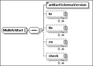
The element artifactSchemaVersion is used to
specify the version of the schema being used. One instance document
may contain any number of the following elements:
- iu
This
element contains one inline definition for each SIU artifact type
(Install, InitialConfig, Migrate, VerifyInstall and Uninstall). An
artifact can be retrieved by knowing its type and the UUID and
version of the referencing IU.
- fix
This element contains one
inline definition for each SIU artifact type. An artifact can be
retrieved by knowing its type and the name of the fix in which it
is referenced.
- cu
This element contains one
inline definition for each CU artifact type (Configure and
VerifyConfig). An artifact can be retrieved by knowing its type and
the CUName internal identifier of the CU.
- check
This element contains the
inline definition of one custom check artifact. A check artifact
can be retrieved by knowing the artifact identifier (artifactId)
specified in the corresponding customCheckArtifact definition
in the root IU.
An iu element is an instance of the
anonymous type illustrated in the following diagram.
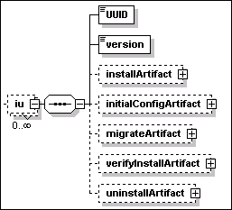
A fix element is an instance of the
anonymous type illustrated in the following diagram.
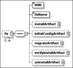
A cu element is an instance of the
anonymous type illustrated in the following diagram.
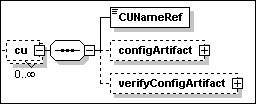
A check element is an instance of the
anonymous type illustrated in the following diagram.
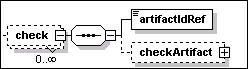
Each one of the OPTIONAL elements under
iu, fix, cu and check illustrated in the above
diagrams are instances of the type ma:ArtifactDefinition. This type
defines a choice among two elements – ActionDefinition and
ResourceProperties Definition – as illustrated in the
following diagram:
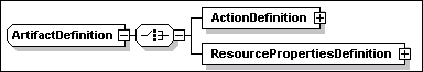
The first element is an instance of
action:Artifact, described in Section 14. The second element is an
instance of config:ConfigArtifact, described in Section 15.
For artifacts defining actions –
instances of action:Artifact – the artifactType element
(instance of action:Artifact) SHOULD match the value of the
type element that is specified by the referencing artifact
element – instance of siu:Artifact – within the SIU or
CU unit element, see Section 9.
Textual information may be associated to
several types defined in the schema. This is possible because those
types include one or more elements that are instances of the
base:DisplayElement type. This type is illustrated by the following
diagram.
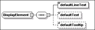
The element provides the ability to specify
the following text elements
·
defaultLineText [type=string]
This element MUST be specified. It should provide text suitable for
display in a single row, e.g. in a table. 200 characters is
the maximum length of the text string that can be
specified.
·
defaultText [type=string]
This element is OPTIONAL and has no restriction of length with
respect to the base XML string type. It should provide text
suitable for display as one or more paragraphs.
·
defaultTooltip [type=string]
This element is OPTIONAL and has a length limit of 60 characters.
It should provide text suitable for display as a short line or a UI
tooltip.
The text specified in the above elements is
the default text and it is always available through the descriptor.
Translated text MAY be available in a resource bundle. Therefore,
each of the above elements MUST specify the following
attribute for binding to the text in the resource
bundle:
·
key [type=NCName]
This element is required. The value can be used to retrieve the
corresponding translated text from the resource bundle.
The
resource bundle, if present, is defined by the
language_bundle attribute of the rootIU element, see Section
5.3. When the language_bundle element is not specified, the default
“iudd_bundle” is used. The value of this attribute
provides the base name for the bundle files, one for each
language. These are text files in the Java property file format, as
described by the java.util.PropertyResourceBundle class in the JAVA
SDK documentation.
This section summarizes the validation rules
within the schema.
The
following identifiers must be unique within the
descriptor:
- IUName in all
IUs and CUName in all
configuration units
- featureID in all
features
- name
in all variables and
checkId in all checks
- customCheckId in
all custom check definitions
- name in
all alternatives (if specified)
- name in
all requirements
- id
in all files
- id
attribute in all targets and
deployed targets
- groupName attribute in all installation groups
- constraintName in all identity constraints
The
following constraints must be respected on references to
identifiers within the descriptor:
- fileIdRef throughout the schema must reference a file
id
- featureIDRef in
groups and IU checks must reference a featureID
- customCheckIdRef in custom checks must reference a customCheckId
- IUNameRef in
deployedTarget must reference an IUName
- IUNameRef in IU
checks must reference an IUName
- CUNameRef in
configuration checks must reference a CUName
- IUNameRef in a
target map must reference an IUName for a
referenced IU. This may be a contained or federated referenced IU,
or a bundled requisite.
- targetRefs throughout the schema must reference a target
id. The targetRef attribute
must be specified if the aggregating IU is a multi-target IU and
the aggregated IU is a single-target IU (e.g. a CIU or a referenced
IU with a targetRef attribute
on the root IU). If the aggregating IU is a single-target IU then
the targetRef attribute
may not be specified: if it is specified, it must have the same
value as the aggregating IU’s target.
- source,
sink and peer
in relationship checks must
reference a target id.
- IUNameRef in a
referenced feature must reference an IUName for a
referenced IU. This may be a contained or federated referenced IU.
It must not be a bundled requisite.
- IUNameRef in a
feature must reference the IUName of a
top-level IU in the selectableContent.
- The list
of identifiers in an identity constraint must reference
checkId.
- softwareCheckRef in an IU discriminant query refers to the
checkId of an IU check.
- IUCheck and SoftwareCheck should contain at least one of the name or
UUID.
- canBeSatisfiedBy in any check or federated IU must reference the
IUName of a bundled requisite IU.
The key uniqueness and key reference
constraints described in this section are not all represented in
the schema. An implementor of tooling for the IU descriptor may
provide additional validation to enforce these constraints.
Version information is defined in the IUDD
schema in one of the two following string formats:
- vsn:GenericVersionString
This type is used for interpreting existing version information
that does not conform to the VRML representation, e.g. in software
checks (see Section 7.3.5).
- vsn:VersionString
This type supports the version/release/modification/level
(VRML) representation, the preferred method used for
specifying new version information. This type is used to specify
the IU version (see Section 5.1) and version information in IU
checks (see Section 7.3.6).
The above types are defined in the schema file
version.xsd reproduced in Appendix H.
The vsn:GenericVersionString representation is
designed to accommodate multi-part, multi-type version
representations (for example, version 5.0 Build 2195 service pack 3
and version 6.0.2600.0000CO). This representation accomplishes the
“interpret liberally” design guideline. The VRML
representation accommodates numeric major/minor version
representation (for example, version 1.3). The VRML representation
accomplishes the “generate strictly” design
guideline.
To compare versions, each version part (a
version part is the version substring between separators, which are
ignored for version comparison) is evaluated from left to right
using either numeric or alphabetic comparison (alphabetic
comparison MUST use a non-Unicode, locale-insensitive,
case-insensitive collating sequence). For version parts that
consist of a number followed by a letter, the numeric part is
compared first: a version part “4a” is greater than a
version part “4”. Comparison stops when the version
parts are different (in this case, the greater version is the one
with the greater version part), when no corresponding version part
exists in one of the versions being compared (in this case, the
greater version is the one with remaining version part(s)) or when
the versions are equal.
A.
Solution Module IUDD example
This is a sample IUDD where root IU
content is a solution module aggregate.
<?xml
version="1.0" encoding="UTF-8"?>
<iudd:rootIU
xmlns:iudd="http://www.ibm.com/namespaces/autonomic/solutioninstall/IUDD"
xmlns:xsi="http://www.w3.org/2001/XMLSchema-instance"
xmlns:OSRT="http://www.ibm.com/namespaces/autonomic/OS_RT"
xmlns:J2EERT="http://www.ibm.com/namespaces/autonomic/J2EE_RT"
xmlns:RDBRT="http://www.ibm.com/namespaces/autonomic/RDB_RT"
xsi:schemaLocation="http://www.ibm.com/namespaces/autonomic/solutioninstall/IUDD
iudd.xsd"
IUName="MySoln">
<identity>
<name>My
Solution</name>
<UUID>11111123456789012345678901234567</UUID>
<displayName>
<defaultLineText key="ST_01">My
Solution</defaultLineText>
</displayName>
<manufacturer>
<defaultLineText
key="ST_02">IBM</defaultLineText>
</manufacturer>
<buildID>MyApp_5.1.abc</buildID>
<buildDate>2001-12-31T12:00:00</buildDate>
<version>1.0.1</version>
</identity>
The root IU identity information includes
a name, UUID and version.
<variables>
<variable
name="BusinessServers">
<resolvedTargetList>
<targetRef>tBusinessSvr</targetRef>
</resolvedTargetList>
</variable>
</variables>
The root IU has one variable, which is
set to the list of resolved targets for the business servers. The
value of this variable is a comma-separated list of the manageable
resource IDs.
<installableUnit>
<containedIU
IUName="myApp">
<fileIdRef>MyAppDescriptor</fileIdRef>
<parameterMaps>
<map>
<internalName>BusinessServers</internalName>
<externalName>TargetServerList</externalName>
</map>
</parameterMaps>
</containedIU>
</installableUnit>
The root IU contains two IUs. The first
is a J2EE application, which is packaged in a referenced IU. The
list of application servers within the cell onto which the
application is to be deployed is passed into the IU as a parameter.
The targeting of this referenced IU will be handled through target
maps, see the tCell target.
<installableUnit
targetRef="tDatabase">
<SIU
IUName="myAppTable">
<identity>
<name>My App Table</name>
<UUID>0F000F000F000F000F000F000F000F00</UUID>
<version>1.0.1</version>
</identity>
<unit>
<installArtifacts>
<installArtifact>
<fileIdRef>MyAppTableArtifact</fileIdRef>
</installArtifact>
<uninstallArtifact>
<fileIdRef>MyAppTableArtifact</fileIdRef>
</uninstallArtifact>
</installArtifacts>
</unit>
</SIU>
</installableUnit>
The second is an inline SIU, which will
install a database table. The SIU is targeted at the tDatabase
target.
<rootInfo>
<schemaVersion>1.2.0</schemaVersion>
<build>157</build>
<size>0</size>
</rootInfo>
Addional root IU information is
provided.
<topology>
<target id="tCell"
type="J2EERT:J2EE_Domain">
<selectionRequirements>
<requirement name="dr1">
<alternative name="alt_1">
<inlineCheck>
<property checkId="IsWebSphereCell">
<propertyName>productName</propertyName>
<value>IBM WebSphere Application
Server</value>
</property>
</inlineCheck>
</alternative>
</requirement>
</selectionRequirements>
<targetMap IUNameRef="myApp">
<externalName>J2EEDomain</externalName>
</targetMap>
</target>
The topology is described. The first
target is a WebSphere cell. A target map is specified, to map this
target into the target named “J2EEDomain” within the
referenced IU. The EAR file will be installed into this target.
<target id="tBusinessSvr"
type="J2EERT:J2EE_Server">
<scope>one</scope>
<selectionRequirements>
<requirement name="dr_3">
<alternative name="alt_3" priority="0">
<inlineCheck>
<property checkId="IsWASServer">
<propertyName>productName</propertyName>
<value>IBM WebSphere Application
Server</value>
</property>
</inlineCheck>
<inlineCheck>
<version checkId="WASVersion">
<propertyName>version</propertyName>
<minVersion>5.1</minVersion>
</version>
</inlineCheck>
<inlineCheck>
<relationship checkId="IsComponentOfCell">
<source>tCell</source>
<type>HasComponent</type>
</relationship>
</inlineCheck>
</alternative>
</requirement>
</selectionRequirements>
</target>
The second target is a subset of the
servers in the cell. The relationship check specifies that they
must be components of the cell; the scope of some indicates that a
selection may be made from the candidates, for example by the
user. These servers must be at least WAS Version 5.1.
When specifying a relationship check,
care needs to be paid to the target with which it is associated.
The target should be the one that is being selected based on the
relationship check. In this example, the requirement is to select
application servers that are components of the selected cell. The
intent is not to select a set of application servers and then
validate whether they are in the same cell.
<target
id="tOperatingSys" type=" OSRT:Operating_System">
<selectionRequirements>
<requirement name="dr_6">
<alternative name="alt_6" priority="0">
<inlineCheck>
<relationship checkId="IsServerOS">
<sink>tBusinessSvr</sink>
<type>Hosts</type>
</relationship>
</inlineCheck>
</alternative>
</requirement>
</selectionRequirements>
<validationRequirements>
<requirement name="dr_5">
<alternative name="alt_5" priority="0">
<inlineCheck>
<software checkId="OracleDriverInstalled">
<UUID>11111123456789012345678901234567</UUID>
<minVersion>7.2</minVersion>
<canBeSatisfiedBy>OracleDriver</canBeSatisfiedBy>
</software>
</inlineCheck>
</alternative>
</requirement>
</validationRequirements>
<targetMap IUNameRef="OracleDriver">
<externalName>OS</externalName>
</targetMap>
</target>
The fourth target is the operating
systems that the application servers in the third target are
running on. The validation requirement tests whether an Oracle
driver is installed. If the driver is not installed, the
canBeSatisfiedBy
reference identifies an IU that will satisfy the dependency, if
installed on the operating system, as indicated by the targetMap.
<target id="tDatabase"
type="RDBRT:Database">
<scope>one</scope>
<selectionRequirements>
<requirement name="dr_7">
<alternative name="alt_7">
<inlineCheck>
<relationship checkId="UsedByCell">
<source>tCell</source>
<type>Uses</type>
</relationship>
</inlineCheck>
</alternative>
</requirement>
</selectionRequirements>
</target>
</topology>
The fourth target is a database that is
being used by the cell.
<requisites>
<referencedIU
IUName="OracleDriver">
<fileIdRef>OracleDriverIUDD</fileIdRef>
</referencedIU>
</requisites>
The root IU ships with the Oracle driver
that is one of its bundled requisites.
<files>
<file
id="MyAppDescriptor">
<pathname>solution/referenced/myApp/IUDD.xml</pathname>
<length>5011</length>
<checksum
type="MD5">1234567890azsxqwedcrfvtgnyhbuij123</checksum>
</file>
<file
id="MyAppTableDDL">
<pathname>solution/artifact/myAppTable/myAppTable.ddl</pathname>
<length>5249</length>
<checksum
type="MD5">5555567890azsxqwedcrfvtgnyhbuij123</checksum>
</file>
<file
id="MyAppTableArtifact">
<pathname>solution/artifacts/myAppTable/Artifact.xml</pathname>
<length>5432</length>
<checksum
type="MD5">5555567890azsxqwedcrfvtgnyhbuij123</checksum>
</file>
<file
id="OracleDriverIUDD">
<pathname>solution/requisites/oracle8.1.1.0/driver/IUDD.xml</pathname>
<length>5249</length>
<checksum
type="MD5">5555567890azsxqwedcrfvtgnyhbuij123</checksum>
</file>
</files>
</iudd:rootIU>
The root IU defines the following
files:
·
The IUDD for the J2EE application
·
The DDL file containing the table definition
·
The artifact descriptor for the table
·
The IUDD for the Oracle Driver
B.
Example of a container installable unit
This is a sample IUDD where root IU
content is a CIU aggregate.
<?xml
version="1.0" encoding="UTF-8"?>
<iudd:rootIU
xmlns:iudd="http://www.ibm.com/namespaces/autonomic/solutioninstall/IUDD"
xmlns:xsi="http://www.w3.org/2001/XMLSchema-instance"
xmlns:OSRT="http://www.ibm.com/namespaces/autonomic/OS_RT"
xsi:schemaLocation="http://www.ibm.com/namespaces/autonomic/solutioninstall/IUDD
iudd.xsd "
IUName="MyAggregatedCIU" targetRef="os" >
<identity>
<name>My Aggregated
CIU</name>
<UUID>41111111111111111111111111111110</UUID>
<version>1.0</version>
</identity>
This
example is a root container installable unit, targeted at the
operating system.
<installableUnit
sequenceNumber="1">
<containedCIU
IUName="xxx">
<fileIdRef>xxx_iudd</fileIdRef>
</containedCIU>
</installableUnit>
The
base content of the CIU is a referenced CIU “xxx”. This
IU has a sequence number of “1”, which means it must be
installed before any of the other top-level IUs (which do not have
a sequence number).
<selectableContent>
<installableUnit>
<containedCIU IUName="yyy">
<fileIdRef>yyy_iudd</fileIdRef>
</containedCIU>
</installableUnit>
<installableUnit>
<containedCIU IUName="zzz">
<fileIdRef>zzz_iudd</fileIdRef>
</containedCIU>
</installableUnit>
<installableUnit>
The
selectable content of the CIU includes two referenced CIUs,
“yyy” and “zzz”.
The
selectable content of the CIU also includes an inline CIU, which
contains two referenced CIUs, “ttt” and
“vvv”.
<CIU
IUName="tttvvv">
<identity>
<name>token</name>
<UUID>0F000F000F000F000F000F000F000F00</UUID>
<version>1.0</version>
</identity>
<installableUnit sequenceNumber="2">
<containedCIU IUName="ttt">
<fileIdRef>ttt_iudd</fileIdRef>
<additionalRequirements>
<target>
<requirements>
<requirement name="ttt_additionalReqt">
<alternative name="isDiskSpaceAvailable">
<inlineCheck>
<consumption checkId="tttDiskSpace">
<propertyName>Filesystem/availableSpace</propertyName>
<value>10</value>
</consumption>
</inlineCheck>
</alternative>
</requirement>
</requirements>
</target>
</additionalRequirements>
</containedCIU>
</installableUnit>
Additional requirements are specified for
“ttt”; specifically, that an additional 10MB of
diskspace is required.
<installableUnit sequenceNumber="1">
<federatedCIU IUName="fedvvv">
<alternative name="alt_55">
<iu checkId="isVVVInstalled">
<name>Component VVV</name>
<minVersion>1.1.3</minVersion>
<canBeSatisfiedBy>vvv</canBeSatisfiedBy>
</iu>
</alternative>
</federatedCIU>
</installableUnit>
</CIU>
</installableUnit>
“vvv” is a federated CIU, meaning that an
existing instance may be reused, providing it satisfies the
specified requirements. If not, the bundled requisite IU should be
installed.
CIU
“vvv” must be installed before CIU “ttt”.
This use of sequence numbers should not bypass the use of expressed
dependencies – i.e. if “ttt” has a prereq on
“vvv”, that should be expressed within the
“ttt” descriptor and that information should be used to
determine sequence information. However, if this dependency is not
identified, at the aggregate level it may be necessary to use
sequence numbers to force installation to occur in an order that is
known to lead to a reliable install.
<installableUnit>
<containedCIU IUName="www">
<fileIdRef>www_iudd</fileIdRef>
</containedCIU>
</installableUnit>
</selectableContent>
The
selectable content of the CIU includes a third referenced CIU,
“www”.
<features>
…
</features>
See
Section C for a description of the use of features in this
example.
<rootInfo>
<schemaVersion>1.2.0</schemaVersion>
<build>1</build>
</rootInfo>
Additional information is provided for the root
IU.
<topology>
<target
type="OSRT:Operating_System" id="os"></target>
</topology>
A
single target is defined. The author of the IU has not constrained
it beyond it being an operating system. Further constraints on this
target would be defined within the referenced CIUs that are part of
this CIU.
<groups>
…
</groups>
See
Section C for a description of the use of groups in this
example.
<requisites>
<referencedIU
IUName="vvv">
<fileIdRef>vvv_iudd</fileIdRef>
</referencedIU>
</requisites>
A
bundled requisite IU is defined to satisfy the need for the
federated IU above. Note that this IU must be a CIU, and will be
targeted at the same OS target as all of the other contained
IUs.
<files>
<file
id="ttt_iudd">
<pathname>myciu/referenced/TTT/IUDD.xml</pathname>
<length>0</length>
<checksum>checksum</checksum>
</file>
<file
id="vvv_iudd">
<pathname>myciu/referenced/VVV/IUDD.xml</pathname>
<length>0</length>
<checksum>checksum</checksum>
</file>
<file
id="www_iudd">
<pathname>myciu/referenced/WWW/IUDD.xml</pathname>
<length>0</length>
<checksum>checksum</checksum>
</file>
<file
id="xxx_iudd">
<pathname>myciu/referenced/XXX/IUDD.xml</pathname>
<length>0</length>
<checksum>checksum</checksum>
</file>
<file
id="yyy_iudd">
<pathname>myciu/referenced/YYY/IUDD.xml</pathname>
<length>0</length>
<checksum>checksum</checksum>
</file>
<file
id="zzz_iudd">
<pathname>myciu/referenced/ZZZ/IUDD.xml</pathname>
<length>0</length>
<checksum>checksum</checksum>
</file>
</files>
</iudd:rootIU>
Files are defined for all of the
descriptors of all of the referenced IUs within this CIU.
C.
Example of features and installation groups
This section builds on the example
described in Section B.
The example CIU defines four top-level
features, Feature A, Feature B, Feature B Plus and Samples.
<features>
<feature
featureID="AFeature">
<identity>
<name>Feature A</name>
</identity>
<feature featureID="A1Feature">
<identity>
<name>Feature
A1</name>
</identity>
<feature featureID="A11Feature" required="true">
<identity>
<name>Feature A1.1</name>
</identity>
<IUNameRef>yyy</IUNameRef>
<IUNameRef>tttvvv</IUNameRef>
</feature>
<feature featureID="A12Feature">
<identity>
<name>Feature A1.2</name>
</identity>
<IUNameRef>zzz</IUNameRef>
</feature>
</feature>
</feature>
Feature A has two levels of nested
features. Feature A1.1 contains CIUs “yyy” and
“tttvvv”. Feature A1.2 contains CIU “zzz”.
Note that the contents of the features must be top-level IUs within
the selectable content, so it would be invalid if a feature
contained “xxx” or “ttt”.
Feature A1.1 is required, i.e. it must be
selected if Feature A1 is selected.
<feature
featureID="BFeature">
<identity>
<name>Feature B</name>
</identity>
<IUNameRef>www</IUNameRef>
<selectionRules>
<deselectIfSelected>BFeaturePlus</deselectIfSelected>
</selectionRules>
</feature>
<feature
featureID="BFeaturePlus">
<identity>
<name>Feature B Plus</name>
</identity>
<IUNameRef>www</IUNameRef>
<IUNameRef>tttvvv</IUNameRef>
<selectionRules>
<deselectIfSelected>BFeature</deselectIfSelected>
</selectionRules>
</feature>
Features B and B Plus has two levels of
nested features. Feature A1.1 contains CIUs “yyy” and
“tttvvv”. These two features are mutually exclusive, so
if one is selected, the other is deselected.
<feature
featureID="Samples">
<identity>
<name>Samples</name>
</identity>
<referencedFeature>
<IUNameRef>xxx</IUNameRef>
<externalName>Samples</externalName>
</referencedFeature>
<referencedFeature>
<ifReq>
<featureIDRef>A11Feature</featureIDRef>
</ifReq>
<IUNameRef>yyy</IUNameRef>
<externalName>Samples</externalName>
</referencedFeature>
</feature>
</features>
The Samples feature contains the
“Samples” feature of the “xxx” CIU. It also
contains the “Samples” feature of the “yyy”
feature, but only if Feature A1.1 is selected. Note the following
scenarios:
If a user installs A1.1 but not Samples,
and then subsequently installs Samples, then yyy Samples should be
installed.
If a user installs Samples but not A1.1,
and then subsequently installs A1.1, then yyy samples should be
installed.
If a user installs Samples and A1.1, and
then uninstalls A1.1, then yyy samples should be uninstalled.
The example CIU has two installation
groups, Typical and Custom. The default installation group is
Typical.
<groups>
<group>
<groupName>Typical</groupName>
<feature featureIDRef="A1Feature" selectionChangeable="false"
selection="selected" />
</group>
<group>
The Typical group selects Feature A1,
which causes Feature A1.1 to be selected, because it is marked as
“required”. The user cannot change the selection of
Feature A1.1, but does have the option of selecting Feature
A1.2.
<groupName>Custom</groupName>
<feature featureIDRef="AFeature" selection="selected"
/>
<feature featureIDRef="BFeature" selection="selected"
/>
<feature featureIDRef="BFeaturePlus" selection="not_selected"
/>
<feature featureIDRef="Samples" selection="not_selected"
/>
</group>
<default>Typical</default>
</groups>
The Custom group allows the user to
select from Features A, B, B Plus and Samples. Features A and B are
by initially selected, and Features B Plus and Samples are not. The
user can change any of the selections of these features, or their
subfeatures, subject to selection rules.
D.
Example of update installable unit
This is a sample IUDD where root IU
content is a CIU aggregate defining an update.
This section describes an incremental update
IU that updates the CIU in Section Bxml version="1.0" encoding="UTF-8"?>
<iudd:rootIU
xmlns:iudd="http://www.ibm.com/namespaces/autonomic/solutioninstall/IUDD"
xmlns:xsi="http://www.w3.org/2001/XMLSchema-instance"
xmlns:OSRT="http://www.ibm.com/namespaces/autonomic/OS_RT"
xsi:schemaLocation="http://www.ibm.com/namespaces/autonomic/solutioninstall/IUDD
iudd.xsd "
IUName="MyAggregatedCIU" targetRef="os">
<identity>
<name>My Aggregated
CIU</name>
<UUID>41111111111111111111111111111110</UUID>
<incremental>
<requiredBase>
<minVersion>1.0.0</minVersion>
</requiredBase>
<type>FixPack</type>
</incremental>
<version>1.0.2</version>
</identity>
This
is an incremental update IU which can update versions 1.0.0 and
1.0.1.
<obsoletedIUs>
<obsoletedIU>
<!--
www should be uninstalled -->
<name>WWW Component</name>
<version>1.0</version>
</obsoletedIU>
</obsoletedIUs>
Any
existing 1.0 “www” IU instance within the IU to be
updated should be uninstalled, because it is obsoleted.
<installableUnit
sequenceNumber="1">
<!-- this must be an
update -->
<containedCIU
IUName="xxx">
<fileIdRef>xxx_iudd</fileIdRef>
</containedCIU>
</installableUnit>
The
existing IU “xxx” is updated.
<selectableContent>
<installableUnit>
<CIU
IUName="tttvvv">
<identity>
<name>token</name>
<UUID>0F000F000F000F000F000F000F000F00</UUID>
<version>1.0.3</version>
</identity>
<installableUnit>
<federatedCIU IUName="fedvvv">
<alternative name=" alt_77">
<iu
checkId="isVVVInstalled">
<name>Component VVV</name>
<minVersion>1.1.3</minVersion>
<canBeSatisfiedBy>vvv</canBeSatisfiedBy>
</iu>
</alternative>
</federatedCIU>
</installableUnit>
</CIU>
</installableUnit>
The
existing IU “vvv” is updated, and so its parent
“tttvvv” is also updated. IU “ttt” is not
updated.
<installableUnit>
<containedCIU
IUName="aaa">
<!-- This must be a full IU -->
<fileIdRef>aaa_iudd</fileIdRef>
</containedCIU>
</installableUnit>
</selectableContent>
A new
“aaa” IU is defined.
<features>
<feature
featureID="BFeature">
<identity>
<name>Feature B</name>
</identity>
<IUNameRef>aaa</IUNameRef>
<selectionRules>
<deselectIfSelected>BFeaturePlus</deselectIfSelected>
</selectionRules>
</feature>
<feature
featureID="BFeaturePlus">
<identity>
<name>Feature B Plus</name>
</identity>
<IUNameRef>aaa</IUNameRef>
<IUNameRef>tttvvv</IUNameRef>
<selectionRules>
<deselectIfSelected>BFeature</deselectIfSelected>
</selectionRules>
</feature>
</features>
The
“aaa” IU replaces “www” in both Feature B
and B Plus. If either of these features are installed, then
“aaa” should be installed and linked to the
features.
<rootInfo>
<schemaVersion>1.2.0</schemaVersion>
<build>1</build>
</rootInfo>
<topology>
<target
type="OSRT:Operating_System" id="os"></target>
</topology>
<requisites>
<referencedIU
IUName="vvv">
<fileIdRef>vvv_iudd</fileIdRef>
</referencedIU>
</requisites>
The
update for the “vvv” IU is contained in a referenced
descriptor.
<files>
<file
id="aaa_iudd">
<pathname>myciu/referenced/AAA/IUDD.xml</pathname>
<length>0</length>
<checksum>checksum</checksum>
</file>
<file
id="vvv_iudd">
<pathname>myciu/referenced/VVV/IUDD.xml</pathname>
<length>0</length>
<checksum>checksum</checksum>
</file>
<file
id="xxx_iudd">
<pathname>myciu/referenced/XXX/IUDD.xml</pathname>
<length>0</length>
<checksum>checksum</checksum>
</file>
</files>
</iudd:rootIU>
E.
iudd.xsd
<?xml
version="1.0" encoding="UTF-8"?>
<
schema targetNamespace
="http://www.ibm.com/namespaces/autonomic/solutioninstall/IUDD
"xmlns:base
="http://www.ibm.com/namespaces/autonomic/solutioninstall/BASE
" xmlns
="http://www.w3.org/2001/XMLSchema
" xmlns:siu
="http://www.ibm.com/namespaces/autonomic/solutioninstall/SIU
"xmlns:command
="http://www.ibm.com/namespaces/autonomic/solutioninstall/command
"xmlns:rtype
="http://www.ibm.com/namespaces/autonomic/solutioninstall/ResourceTypes
" xmlns:vsn
="http://www.ibm.com/namespaces/autonomic/common/version
"xmlns:iudd
="http://www.ibm.com/namespaces/autonomic/solutioninstall/IUDD
"elementFormDefault
="unqualified
"attributeFormDefault
="unqualified
" version
="1.2.1
">
<
annotation>
<
documentation>
ACAB.SD0402 - Installable Unit Deployment Descriptor (IUDD) -
Copyright (C) 2003,2004 IBM Corporation. All rights
reserved</
documentation>
</
annotation>
<
import namespace
="http://www.ibm.com/namespaces/autonomic/solutioninstall/BASE
"schemaLocation
="base.xsd
"/>
<
import namespace
="http://www.ibm.com/namespaces/autonomic/solutioninstall/SIU
"schemaLocation
="siu.xsd
"/>
<
import namespace
="http://www.ibm.com/namespaces/autonomic/solutioninstall/ResourceTypes
"schemaLocation
="resourceTypes.xsd
"/>
<
import namespace
="http://www.ibm.com/namespaces/autonomic/common/version
"schemaLocation
="version.xsd
"/>
<!--
##### Root IU #############-->
<
element name
="rootIU
" type
="iudd:RootIU
">
<
key name
="fileKey
">
<
selector xpath
="files/file
"/>
<
field xpath
="@id
"/>
</
key>
<
keyref name
="fileIdRef
" refer
="iudd:fileKey
">
<
selector xpath
=".//fileIdRef
"/>
<
field xpath
=".
"/>
</
keyref>
<
keyref name
="bigIconFileIdRef
" refer
="iudd:fileKey
">
<
selector xpath
="rootInfo/bigIcon
"/>
<
field xpath
="@fileIdRef
"/>
</
keyref>
<
keyref name
="smallIconFileIdRef
" refer
="iudd:fileKey
">
<
selector xpath
="rootInfo/smallIcon
"/>
<
field xpath
="@fileIdRef
"/>
</
keyref>
<
key name
="customCheckArtifactKey
">
<
selector xpath
="customCheckDefinitions/*
"/>
<
field xpath
="@artifactId
"/>
</
key>
<
keyref name
="customCheckIdRef
" refer
="iudd:customCheckArtifactKey
">
<
selector xpath
=".//custom
"/>
<
field xpath
="@artifactIdRef
"/>
</
keyref>
<
key name
="AllButRootIUNameKey
">
<
selector xpath
=".//referencedIU
| .//SIU | .//containedCIU | .//federatedCIU | .//containedIU |
.//federatedIU | .//solutionModule | .//CIU |
.//configurationUnit "/>
<
field xpath
="@IUName
| @CUName"/>
</
key>
<
key name
="AllCUNameKey
">
<
selector xpath
=".//configurationUnit
"/>
<
field xpath
="@CUName
"/>
</
key>
<
keyref name
="AllCUNameKeyRef
" refer
="iudd:AllCUNameKey
">
<
selector xpath
=".//config
"/>
<
field xpath
="CUNameRef
"/>
</
keyref>
<
key name
="referencedIUNameKey
">
<
selector xpath
=".//referencedIU
| .//containedCIU | .//containedIU "/>
<
field xpath
="@IUName
"/>
</
key>
<
key name
="referencedAggregatedIUNameKey
">
<
selector xpath
=".//containedCIU
| .//containedIU | .//federatedCIU | .//federatedIU |
.//referencedIU"/>
<
field xpath
="@IUName
"/>
</
key>
<
keyref name
="referencedIUAttrNameKeyRef
" refer
="iudd:referencedIUNameKey
">
<
selector xpath
=".//targetMap
"/>
<
field xpath
="@IUNameRef
"/>
</
keyref>
<
keyref name
="referencedAggregatedIUNameKeyRef
" refer
="iudd:referencedAggregatedIUNameKey
">
<
selector xpath
=".//referencedFeature
"/>
<
field xpath
="IUNameRef
"/>
</
keyref>
<
key name
="requisiteIUNameKey
">
<
selector xpath
=".//referencedIU
"/>
<
field xpath
="@IUName
"/>
</
key>
<
keyref name
="iuRequisiteIUNameKeyRef
" refer
="iudd:requisiteIUNameKey
">
<
selector xpath
=".//canBeSatisfiedBy
"/>
<
field xpath
=".
"/>
</
keyref>
<
key name
="selectableIUNameKey
">
<
selector xpath
="selectableContent/installableUnit/*
"/>
<
field xpath
="@IUName
"/>
</
key>
<
keyref name
="selectableIUElementNameKeyRef
" refer
="iudd:selectableIUNameKey
">
<
selector xpath
=".//feature/IUNameRef
"/>
<
field xpath
=".
"/>
</
keyref>
<
key name
="AllVariableNameKey
">
<
selector xpath
=".//variables/variable
| .//checks/* | .//inlineCheck/* | .//alternative/iu
"/>
<
field xpath
="@name
| @checkId"/>
</
key>
<
key name
="targetKey
">
<
selector xpath
=".//topology/target
| .//topology/deployedTarget "/>
<
field xpath
="@id
"/>
</
key>
<
keyref name
="targetRef
" refer
="iudd:targetKey
">
<
selector xpath
=".//targetRef
"/>
<
field xpath
=".
"/>
</
keyref>
<
keyref name
="relnSourceRef
" refer
="iudd:targetKey
">
<
selector xpath
=".//relationship/source
"/>
<
field xpath
=".
"/>
</
keyref>
<
keyref name
="relnSinkRef
" refer
="iudd:targetKey
">
<
selector xpath
=".//relationship/sink
"/>
<
field xpath
=".
"/>
</
keyref>
<
keyref name
="relnPeerRef
" refer
="iudd:targetKey
">
<
selector xpath
=".//relationship/peer
"/>
<
field xpath
=".
"/>
</
keyref>
<
key name
="groupKey
">
<
selector xpath
="groups/group
"/>
<
field xpath
="groupName
"/>
</
key>
<
keyref name
="groupRef
" refer
="iudd:groupKey
">
<
selector xpath
="groups/default
"/>
<
field xpath
=".
"/>
</
keyref>
<
key name
="reqtKey
">
<
selector xpath
=".//requirement
"/>
<
field xpath
="@name
"/>
</
key>
<
key name
="altKey
">
<
selector xpath
=".//requirement/alternative
"/>
<
field xpath
="@name
"/>
</
key>
</
element>
<
complexType name
="RootIU
">
<
complexContent>
<
extension base
="iudd:AggregatedInstallableUnit
">
<
sequence>
<
element name
="selectableContent
" minOccurs
="0
">
<
complexType>
<
sequence>
<
element name
="installableUnit
" type
="iudd:ConditionedIU
" maxOccurs
="unbounded
"/>
</
sequence>
</
complexType>
</
element>
<
element name
="features
" minOccurs
="0
">
<
complexType>
<
sequence>
<
element name
="feature
" type
="iudd:Feature
" maxOccurs
="unbounded
"/>
</
sequence>
</
complexType>
</
element>
<
element name
="rootInfo
">
<
complexType>
<
sequence>
<
element name
="schemaVersion
">
<
simpleType>
<
restriction base
="vsn:VersionString
">
<
enumeration value
="1.2.1
"/>
</
restriction>
</
simpleType>
</
element>
<
element name
="build
" type
="nonNegativeInteger
"/>
<
element name
="size
" type
="integer
" minOccurs
="0
"/>
<
element name
="bigIcon
" minOccurs
="0
">
<
complexType>
<
attribute name
="fileIdRef
" type
="IDREF
"/>
</
complexType>
</
element>
<
element name
="smallIcon
" minOccurs
="0
">
<
complexType>
<
attribute name
="fileIdRef
" type
="IDREF
"/>
</
complexType>
</
element>
<
element name
="type
" minOccurs
="0
">
<
simpleType>
<
restriction base
="NCName
">
<
enumeration value
="Offering
"/>
<
enumeration value
="Assembly
"/>
<
enumeration value
="CommonComponent
"/>
</
restriction>
</
simpleType>
</
element>
</
sequence>
</
complexType>
</
element>
<
element name
="customCheckDefinitions
" minOccurs
="0
" maxOccurs
="unbounded
">
<
complexType>
<
sequence>
<
element name
="customCheckArtifact
" type
="siu:CustomCheckArtifact
" maxOccurs
="unbounded
"/>
</
sequence>
</
complexType>
</
element>
<
element name
="topology
">
<
complexType>
<
sequence>
<
element name
="target
" type
="iudd:Target
" maxOccurs
="unbounded
"/>
<
element name
="deployedTarget
" type
="iudd:DeployedTarget
" minOccurs
="0
" maxOccurs
="unbounded
"/>
</
sequence>
</
complexType>
</
element>
<
element name
="groups
" minOccurs
="0
">
<
complexType>
<
sequence>
<
element name
="group
" type
="iudd:InstallationGroup
" maxOccurs
="unbounded
"/>
<
element name
="default
" type
="token
" minOccurs
="0
"/>
</sequence>
</complexType>
</element>
<elementname="requisites"minOccurs="0">
<complexType>
<sequence>
<
element name
="referencedIU
" type
="iudd:ReferencedIU
" maxOccurs
="unbounded
"/>
</
sequence>
</
complexType>
</
element>
<
element name
="files
">
<
complexType>
<
sequence>
<
element name
="file
" type
="iudd:File
" maxOccurs
="unbounded
"/>
</
sequence>
</
complexType>
</
element>
</
sequence>
<
attribute name
="targetRef
" type
="IDREF
" use
="optional
"/>
<
attribute name
="language_bundle
" type
="token
" use
="optional
" default
="iudd_bundle
"/>
</
extension>
</
complexContent>
</
complexType>
<
complexType name
="ReferencedIU
">
<
sequence>
<
element name
="fileIdRef
" type
="IDREF
"/>
<
element name
="parameterMaps
" type
="base:Maps
" minOccurs
="0
"/>
<
element name
="featureSelections
" minOccurs
="0
">
<
complexType>
<
sequence>
<
element name
="externalInstallGroup
" type
="token
" minOccurs
="0
"/>
<
element name
="featureSelection
" minOccurs
="0
" maxOccurs
="unbounded
">
<
complexType>
<
sequence>
<
element name
="externalName
" type
="token
"/>
<
element name
="selection
" type
="iudd:Selection
"/>
</
sequence>
</
complexType>
</
element>
</
sequence>
</
complexType>
</
element>
<
element name
="additionalRequirements
" minOccurs
="0
">
<
complexType>
<
sequence>
<
element name
="target
" maxOccurs
="unbounded
">
<
complexType>
<
sequence>
<
element name
="checks
" type
="siu:CheckSequence
" minOccurs
="0
"/>
<
element name
="requirements
" minOccurs
="0
">
<
complexType>
<
sequence>
<
element name
="requirement
" type
="siu:Requirement
" maxOccurs
="unbounded
"/>
</
sequence>
</
complexType>
</
element>
</
sequence>
<
attribute name
="targetRef
" type
="IDREF
"/>
</complexType>
</element>
</sequence>
</complexType>
</element>
</
sequence>
<
attribute name
="IUName
" type
="ID
" use
="required
"/>
</
complexType>
<
complexType name
="ReferencedFeature
">
<
sequence>
<
element name
="ifReq
" minOccurs
="0
">
<
complexType>
<
sequence>
<
element name
="featureIDRef
" type
="IDREF
" maxOccurs
="unbounded
"/>
</
sequence>
</
complexType>
</
element>
<
element name
="IUNameRef
" type
="IDREF
"/>
<
element name
="externalName
" type
="token
"/>
</
sequence>
</
complexType>
<
complexType name
="FederatedIU
">
<
sequence>
<
element name
="alternative
" maxOccurs
="unbounded
">
<
complexType>
<
sequence>
<
element name
="iu
" type
="base:IUCheck
"/>
</
sequence>
</
complexType>
</
element>
</
sequence>
<
attribute name
="IUName
" type
="ID
" use
="required
"/>
</
complexType>
<!--
##### Aggregated Installable Units - base types
#####-->
<
group name
="SingleTargetIU
">
<
choice>
<
element name
="SIU
" type
="siu:SmallestInstallableUnit
"/>
<
element name
="CIU
" type
="iudd:ContainerInstallableUnit
"/>
<
element name
="containedCIU
" type
="iudd:ReferencedIU
"/>
<
element name
="federatedCIU
" type
="iudd:FederatedIU
"/>
<
element name
="configurationUnit
" type
="siu:ConfigurationUnit
"/>
</
choice>
</
group>
<
complexType name
="ConditionedIU
">
<
choice>
<
group ref
="iudd:SingleTargetIU
"/>
<
element name
="solutionModule
" type
="iudd:SolutionModule
"/>
<
element name
="containedIU
" type
="iudd:ReferencedIU
"/>
<
element name
="federatedIU
" type
="iudd:FederatedIU
"/>
</
choice>
<
attribute name
="targetRef
" type
="IDREF
" use
="optional
"/>
<
attribute name
="condition
" type
="base:VariableExpression
" use
="optional
"/>
<
attribute name
="sequenceNumber
" type
="nonNegativeInteger
"/>
</
complexType>
<
complexType name
="AggregatedInstallableUnit
" abstract
="true
">
<complexContent>
<extensionbase="siu:InstallableUnit">
<sequence>
<elementname="installableUnit"type="iudd:ConditionedIU"minOccurs="0"maxOccurs="unbounded"/>
</sequence>
</extension>
</complexContent>
</complexType>
<!--##### Solution Module Installable Unit
#####-->
<complexTypename="SolutionModule">
<complexContent>
<extensionbase="iudd:AggregatedInstallableUnit"/>
</complexContent>
</complexType>
<!--##### Container Installable Unit
#####################-->
<complexTypename="ContainerInstallableUnit">
<complexContent>
<extensionbase="iudd:AggregatedInstallableUnit">
<sequence>
<groupref="siu:SingleTargetIUDefinition"/>
</sequence>
<attributename="hostingEnvType"type="siu:AnyResourceType"/>
</extension>
</complexContent>
</complexType>
<!--##### TARGET #####################-->
<complexTypename="Target">
<sequence>
<elementname="description"type="base:DisplayElement"minOccurs="0"/>
<elementname="scope"default="one"minOccurs="0">
<
simpleType>
<
restriction base
="NCName
">
<
enumeration value
="one
"/>
<
enumeration value
="some
"/>
<
enumeration value
="all
"/>
</
restriction>
</
simpleType>
</
element>
<
element name
="members
" minOccurs
="0
">
<
complexType>
<
sequence>
<
element name
="member
" type
="IDREF
" maxOccurs
="unbounded
"/>
</
sequence>
</
complexType>
</
element>
<
element name
="checks
" type
="siu:CheckSequence
" minOccurs
="0
"/>
<
element name
="selectionRequirements
" minOccurs
="0
">
<
complexType>
<
sequence>
<
element name
="requirement
" type
="siu:Requirement
" maxOccurs
="unbounded
"/>
</
sequence>
</
complexType>
</
element>
<
element name
="validationRequirements
" minOccurs
="0
">
<
complexType>
<
sequence>
<
element name
="requirement
" type
="siu:Requirement
" maxOccurs
="unbounded
"/>
</
sequence>
</
complexType>
</
element>
<
element name
="targetMap
" type
="iudd:TargetMap
" minOccurs
="0
" maxOccurs
="unbounded
"/>
</
sequence>
<
attribute name
="id
" type
="ID
" use
="required
"/>
<
attribute name
="type
" type
="siu:AnyResourceType
" use
="required
"/>
</
complexType>
<
complexType name
="DeployedTarget
">
<
sequence>
<
element name
="description
" type
="base:DisplayElement
" minOccurs
="0
"/>
<
choice>
<
element name
="IUNameRef
" type
="IDREF
"/>
<
element name
="targetMap
" type
="iudd:TargetMap
"/>
</
choice>
</
sequence>
<
attribute name
="id
" type
="ID
" use
="required
"/>
<
attribute name
="type
" type
="siu:AnyResourceType
" use
="required
"/>
</
complexType>
<
complexType name
="TargetMap
">
<
sequence>
<
element name
="externalName
" type
="NCName
" maxOccurs
="unbounded
"/>
</
sequence>
<
attribute name
="IUNameRef
" type
="IDREF
" use
="required
"/>
</
complexType>
<!--
##### Files ########################-->
<
complexType name
="File
">
<
sequence>
<
element name
="pathname
" type
="base:RelativePath
"/>
<
element name
="length
" type
="integer
"/>
<
element name
="checksum
" type
="base:CheckSum
"/>
</
sequence>
<
attribute name
="id
" type
="ID
" use
="required
"/>
<
attribute name
="compression
" type
="boolean
" use
="optional
" default
="true
"/>
<
attribute name
="charEncoding
" type
="base:CharacterEncoding
" use
="optional
"/>
</
complexType>
<!--
##### GROUPS & FEATURES ############-->
<
simpleType name
="Selection
">
<
restriction base
="NCName
">
<
enumeration value
="not_selected
"/>
<
enumeration value
="selected
"/>
</
restriction>
</
simpleType>
<
complexType name
="InstallationGroup
">
<
sequence>
<
element name
="groupName
" type
="token
"/>
<
element name
="feature
" maxOccurs
="unbounded
">
<
complexType>
<
attribute name
="featureIDRef
" type
="IDREF
" use
="required
"/>
<
attribute name
="selection
" type
="iudd:Selection
" default
="selected
"/>
<
attribute name
="selectionChangeable
" type
="boolean
" default
="true
"/>
</
complexType>
</
element>
<
element name
="description
" type
="base:DisplayElement
" minOccurs
="0
"/>
</
sequence>
</
complexType>
<
complexType name
="Feature
">
<
sequence>
<
group ref
="iudd:FeatureDefinition
"/>
<
element name
="feature
" type
="iudd:Feature
" minOccurs
="0
" maxOccurs
="unbounded
"/>
<
element name
="IUNameRef
" type
="IDREF
" minOccurs
="0
" maxOccurs
="unbounded
"/>
<
element name
="referencedFeature
" type
="iudd:ReferencedFeature
" minOccurs
="0
" maxOccurs
="unbounded
"/>
<
element name
="selectionRules
" minOccurs
="0
">
<
complexType>
<
sequence>
<
element name
="selectIfSelected
" type
="IDREF
" minOccurs
="0
" maxOccurs
="unbounded
"/>
<
element name
="deselectIfSelected
" type
="IDREF
" minOccurs
="0
" maxOccurs
="unbounded
"/>
<
element name
="selectIfDeselected
" type
="IDREF
" minOccurs
="0
" maxOccurs
="unbounded
"/>
<
element name
="deselectIfDeselected
" type
="IDREF
" minOccurs
="0
" maxOccurs
="unbounded
"/>
</
sequence>
</
complexType>
</
element>
</
sequence>
<
attribute name
="featureID
" type
="ID
" use
="required
"/>
<
attribute name
="required
" type
="boolean
" default
="false
"/>
<
attribute name
="type
" type
="iudd:FeatureType
"/>
</
complexType>
<
group name
="FeatureDefinition
">
<
sequence>
<
element name
="identity
">
<
complexType>
<
sequence>
<
element name
="name
" type
="token
"/>
<
element name
="displayName
" type
="base:DisplayElement
" minOccurs
="0
"/>
</
sequence>
</
complexType>
</
element>
</
sequence>
</
group>
<
simpleType name
="FeatureType
">
<
unionmemberTypes
="NCName
iudd:StandardFeatureType"/>
</
simpleType>
<
simpleType name
="StandardFeatureType
">
<
restriction base
="NCName
">
<
enumeration value
="Documentation
"/>
<
enumeration value
="Language
"/>
<
enumeration value
="Samples
"/>
</
restriction>
</
simpleType>
</
schema>
F.
siu.xsd
<?xml
version="1.0" encoding="UTF-8"?>
<
schema targetNamespace
="http://www.ibm.com/namespaces/autonomic/solutioninstall/SIU
"xmlns:rtype
="http://www.ibm.com/namespaces/autonomic/solutioninstall/ResourceTypes
" xmlns:vsn
="http://www.ibm.com/namespaces/autonomic/common/version
" xmlns:siu
="http://www.ibm.com/namespaces/autonomic/solutioninstall/SIU
"xmlns:base
="http://www.ibm.com/namespaces/autonomic/solutioninstall/BASE
"xmlns:sigt
="http://www.ibm.com/namespaces/autonomic/solutioninstall/Signatures
" xmlns
="http://www.w3.org/2001/XMLSchema
"elementFormDefault
="unqualified
"attributeFormDefault
="unqualified
" version
="1.2.1
">
<
annotation>
<
documentation>
ACAB.SD0402 - Installable Unit Deployment Descriptor (IUDD) -
Copyright (C) 2003,2004 IBM Corporation. All rights
reserved</
documentation>
</
annotation>
<
import namespace
="http://www.ibm.com/namespaces/autonomic/solutioninstall/Signatures
"schemaLocation
="signatures.xsd
"/>
<
import namespace
="http://www.ibm.com/namespaces/autonomic/solutioninstall/ResourceTypes
"schemaLocation
="resourceTypes.xsd
"/>
<
import namespace
="http://www.ibm.com/namespaces/autonomic/solutioninstall/BASE
"schemaLocation
="base.xsd
"/>
<
import namespace
="http://www.ibm.com/namespaces/autonomic/common/version
"schemaLocation
="version.xsd
"/>
<!--
##### IU Definition #########################-->
<
group name
="IUDefinition
">
<
sequence>
<
element name
="identity
" type
="base:IUIdentity
">
<
annotation>
<documentation>Installable Unit Identity</documentation>
</annotation>
</element>
<elementname="constraints"minOccurs="0">
<annotation>
<documentation>Sharing and multiplicity
constraints</documentation>
</annotation>
<complexType>
<sequence>
<elementname="maximumInstances"type="nonNegativeInteger"minOccurs="0"/>
<
element name
="maximumSharing
" minOccurs
="0
">
<
complexType>
<
simpleContent>
<
extension base
="nonNegativeInteger
">
<
attribute name
="sharedBy_List
" type
="base:ListOfUUIDs
" use
="optional
"/>
</
extension>
</
simpleContent>
</
complexType>
</
element>
</
sequence>
</
complexType>
</
element>
<
element name
="obsoletedIUs
" minOccurs
="0
">
<
complexType>
<
sequence>
<
element name
="obsoletedIU
" maxOccurs
="unbounded
">
<
complexType>
<
choice>
<
element name
="name
" type
="token
"/>
<
element name
="UUID
" type
="base:UUID
"/>
</
choice>
</
complexType>
</
element>
</
sequence>
</
complexType>
</
element>
</
sequence>
</
group>
<
group name
="FixDefinition
">
<
sequence>
<
element name
="fixIdentity
" type
="base:FixIdentity
"/>
</
sequence>
</
group>
<
group name
="IUorFixDefinition
">
<
sequence>
<
choice>
<
sequence>
<
group ref
="siu:IUDefinition
"/>
</
sequence>
<
sequence>
<
group ref
="siu:FixDefinition
"/>
</
sequence>
</
choice>
<
element name
="supersededFixes
" type
="base:ListOfIdentifiers
" minOccurs
="0
">
<
annotation>
<
documentation>
These are fix names for this UUID</
documentation>
</
annotation>
</
element>
</
sequence>
</
group>
<
group name
="CUDefinition
">
<
sequence>
<
element name
="displayName
" type
="base:DisplayElement
" minOccurs
="0
"/>
<
element name
="manufacturer
" type
="base:DisplayElement
" minOccurs
="0
"/>
<
element name
="checks
" type
="siu:CheckSequence
" minOccurs
="0
"/>
<
element name
="requirements
" minOccurs
="0
">
<
complexType>
<
sequence>
<
element name
="requirement
" type
="siu:Requirement
" maxOccurs
="unbounded
"/>
</
sequence>
</
complexType>
</
element>
</
sequence>
</
group>
<!--
##### Smallest Installable Unit ################-->
<
complexType name
="InstallableUnit
">
<
sequence>
<
group ref
="siu:IUorFixDefinition
"/>
<
group ref
="base:Variables
"/>
</
sequence>
<
attribute name
="IUName
" type
="ID
" use
="required
"/>
</
complexType>
<
group name
="SingleTargetIUDefinition
">
<
sequence>
<elementname="signatures"minOccurs="0">
<complexType>
<sequence>
<elementname="signature"type="sigt:Signature"maxOccurs="unbounded"/>
</sequence>
</complexType>
</element>
<elementname="checks"type="siu:CheckSequence"minOccurs="0"/>
<elementname="requirements"minOccurs="0">
<complexType>
<sequence>
<elementname="requirement"type="siu:Requirement"maxOccurs="unbounded"/>
</sequence>
</complexType>
</element>
</sequence>
</group>
<complexTypename="SmallestInstallableUnit">
<complexContent>
<extensionbase="siu:InstallableUnit">
<
sequence>
<
group ref
="siu:SingleTargetIUDefinition
"/>
<
element name
="unit
" type
="siu:InstallArtifactSet
" maxOccurs
="unbounded
"/>
</
sequence>
<
attribute name
="hostingEnvType
" type
="siu:AnyResourceType
"/>
</
extension>
</
complexContent>
</
complexType>
<
complexType name
="ConfigurationUnit
">
<
sequence>
<
group ref
="siu:CUDefinition
"/>
<
group ref
="base:Variables
"/>
<
element name
="unit
" type
="siu:ConfigurationArtifactSet
" maxOccurs
="unbounded
"/>
</
sequence>
<
attribute name
="CUName
" type
="ID
" use
="required
"/>
<
attribute name
="resourceType
" type
="siu:AnyResourceType
"/>
</
complexType>
<!--
##### CHECKS ###########################-->
<
complexType name
="CustomCheck
">
<complexContent>
<extensionbase="base:Check">
<
sequence>
<
element name
="parameter
" minOccurs
="0
" maxOccurs
="unbounded
">
<
complexType>
<
annotation>
<
documentation>
Setting a parameter of a custom check</
documentation>
</annotation>
<simpleContent>
<extensionbase="base:VariableExpression">
<
attribute name
="variableNameRef
" type
="IDREF
" use
="required
"/>
</extension>
</simpleContent>
</complexType>
</element>
</sequence>
<
attribute name
="artifactIdRef
" type
="IDREF
" use
="required
"/>
</
extension>
</
complexContent>
</
complexType>
<
complexType name
="CustomCheckArtifact
">
<
complexContent>
<
extension base
="siu:Artifact
">
<
attribute name
="artifactId
" type
="ID
" use
="required
"/>
</
extension>
</
complexContent>
</
complexType>
<
group name
="CheckChoice
">
<
choice>
<
element name
="capacity
" type
="base:CapacityCheck
"/>
<
element name
="consumption
" type
="base:ConsumptionCheck
"/>
<
element name
="property
" type
="base:PropertyCheck
"/>
<
element name
="version
" type
="base:VersionCheck
"/>
<
element name
="software
" type
="base:SoftwareCheck
"/>
<
element name
="iu
" type
="base:IUCheck
"/>
<
element name
="relationship
" type
="base:RelationshipCheck
"/>
<
element name
="custom
" type
="siu:CustomCheck
"/>
</
choice>
</
group>
<
complexType name
="CheckSequence
">
<
sequence minOccurs
="0
" maxOccurs
="unbounded
">
<
group ref
="siu:CheckChoice
"/>
</
sequence>
</
complexType>
<!--
##### REQUIREMENTS #####################-->
<
complexType name
="Requirement
">
<
sequence>
<
element name
="description
" type
="base:DisplayElement
" minOccurs
="0
"/>
<
element name
="alternative
" maxOccurs
="unbounded
">
<
annotation>
<documentation>conditions in .OR.</documentation>
</annotation>
<complexType>
<annotation>
<documentation>conditions in .AND.</documentation>
</annotation>
<sequence>
<elementname="description"type="base:DisplayElement"minOccurs="0"/>
<choicemaxOccurs="unbounded">
<
element name
="checkItem
">
<
complexType>
<
attribute name
="checkIdRef
" type
="IDREF
" use
="required
"/>
<
attribute name
="testValue
" type
="boolean
" use
="optional
" default
="true
"/>
</
complexType>
</
element>
<
element name
="inlineCheck
">
<
complexType>
<
group ref
="siu:CheckChoice
"/>
<
attribute name
="testValue
" type
="boolean
" use
="optional
" default
="true
"/>
</
complexType>
</
element>
</
choice>
</
sequence>
<
attribute name
="name
" type
="ID
" use
="required
"/>
<
attribute name
="priority
" type
="nonNegativeInteger
" use
="optional
"/>
</
complexType>
</
element>
</
sequence>
<
attribute name
="name
" type
="ID
" use
="required
"/>
<
attribute name
="operations
" type
="base:ListOfOperations
" default
="Create
"/>
</
complexType>
<!--
##### ARTIFACTS #####################-->
<
complexType name
="InstallArtifactSet
">
<
sequence>
<
element name
="installArtifacts
">
<
complexType>
<
sequence>
<
element name
="installArtifact
" type
="siu:UndoableArtifact
" minOccurs
="0
"/>
<
element name
="initialConfigArtifact
" type
="siu:UndoableArtifact
" minOccurs
="0
"/>
<
element name
="migrateArtifact
" type
="siu:UndoableArtifact
" minOccurs
="0
"/>
<
element name
="verifyInstallArtifact
" type
="siu:Artifact
" minOccurs
="0
"/>
<
element name
="uninstallArtifact
" type
="siu:Artifact
" minOccurs
="0
"/>
</
sequence>
</
complexType>
</
element>
</
sequence>
<
attribute name
="condition
" type
="base:VariableExpression
" use
="optional
" default
="true
"/>
</
complexType>
<
complexType name
="ConfigurationArtifactSet
">
<
sequence>
<
element name
="configArtifacts
">
<
complexType>
<
sequence>
<
element name
="configArtifact
" type
="siu:Artifact
" minOccurs
="0
"/>
<
element name
="verifyConfigArtifact
" type
="siu:Artifact
" minOccurs
="0
"/>
</
sequence>
</
complexType>
</
element>
</
sequence>
<
attribute name
="condition
" type
="base:VariableExpression
" use
="optional
" default
="true
"/>
</
complexType>
<
complexType name
="Artifact
">
<
sequence>
<
element name
="fileIdRef
" type
="IDREF
"/>
<elementname="type"type="siu:ArtifactFormat"default="ActionDefinition"minOccurs="0">
<annotation>
<documentation>ActionDefinition, ResourcePropertiesDefinition,
...</documentation>
</annotation>
</element>
<elementname="parameterMaps"type="base:Maps"minOccurs="0">
<annotation>
<documentation>Provide/Override value of artifact parameter
variables</documentation>
</annotation>
</
element>
</
sequence>
<
attribute name
="HE_restart_required
" type
="boolean
" use
="optional
" default
="false
">
<
annotation>
<
documentation>
If enabled, this attribute indicates that a hosting environment
restart (e.g. OS reboot)is needed after processing actions in this
artifact.</
documentation>
</
annotation>
</
attribute>
</
complexType>
<
complexType name
="UndoableArtifact
">
<
complexContent>
<
extension base
="siu:Artifact
">
<
attribute name
="undoable
" type
="boolean
" use
="optional
" default
="false
"/>
</
extension>
</
complexContent>
</
complexType>
<
simpleType name
="ArtifactFormat
">
<
unionmemberTypes
="NCName
siu:StandardArtifactFormat"/>
</
simpleType>
<
simpleType name
="StandardArtifactFormat
">
<
restriction base
="NCName
">
<
enumeration value
="ActionDefinition
"/>
<
enumeration value
="ResourcePropertiesDefinition
"/>
</
restriction>
</
simpleType>
<!--
##### HE Types #####################-->
<
simpleType name
="AnyResourceType
">
<
unionmemberTypes
="rtype:RType
QName"/>
</
simpleType>
</
schema>
G.
base.xsd
<?xml
version="1.0" encoding="UTF-8"?>
<
schema targetNamespace
="http://www.ibm.com/namespaces/autonomic/solutioninstall/BASE
"xmlns:base
="http://www.ibm.com/namespaces/autonomic/solutioninstall/BASE
" xmlns
="http://www.w3.org/2001/XMLSchema
" xmlns:vsn
="http://www.ibm.com/namespaces/autonomic/common/version
" xmlns:rel
="http://www.ibm.com/namespaces/autonomic/solutioninstall/Relationships
"elementFormDefault
="unqualified
"attributeFormDefault
="unqualified
" version
="1.2.1
">
<
import namespace
="http://www.ibm.com/namespaces/autonomic/solutioninstall/Relationships
"schemaLocation
="relationships.xsd
"/>
<
import namespace
="http://www.ibm.com/namespaces/autonomic/common/version
"schemaLocation
="version.xsd
"/>
<
annotation>
<
documentation>
ACAB.SD0402 - Installable Unit Deployment Descriptor (IUDD) -
Copyright (C) 2003,2004 IBM Corporation. All rights
reserved</
documentation>
</
annotation>
<!--
##### DISPLAY ELEMENTS ########################-->
<
simpleType name
="LineOfText
">
<
restriction base
="string
">
<
maxLength value
="200
"/>
</
restriction>
</
simpleType>
<
simpleType name
="TooltipText
">
<
restriction base
="string
">
<
maxLength value
="60
"/>
</
restriction>
</
simpleType>
<
complexType name
="DisplayElement
">
<
sequence>
<
element name
="defaultLineText
">
<
complexType>
<
simpleContent>
<
extension base
="base:LineOfText
">
<
attribute name
="key
" type
="NCName
" use
="required
"/>
</extension>
</simpleContent>
</complexType>
</element>
<elementname="defaultText"minOccurs="0">
<complexType>
<simpleContent>
<extensionbase="string">
<
attribute name
="key
" type
="NCName
" use
="required
"/>
</extension>
</simpleContent>
</complexType>
</element>
<elementname="defaultTooltip"minOccurs="0">
<complexType>
<simpleContent>
<extensionbase="base:TooltipText">
<
attribute name
="key
" type
="NCName
" use
="required
"/>
</extension>
</simpleContent>
</complexType>
</element>
</sequence>
</complexType>
<!--##### IDENTIFIERS AND EXPRESSIONS
###############-->
<simpleTypename="ListOfIdentifiers">
<listitemType="NCName"/>
</simpleType>
<simpleTypename="ListOfIDREFs">
<listitemType="IDREF"/>
</simpleType>
<simpleTypename="VariableExpression">
<
restriction base
="token
">
<
pattern value
="([^$]*($[^(])*($\([a-zA-Z_]+[0-9a-zA-Z_]*\))*)*
"/>
</
restriction>
</
simpleType>
<
simpleType name
="UUID
">
<
restriction base
="hexBinary
">
<
length value
="16
"/>
</
restriction>
</
simpleType>
<
simpleType name
="ListOfUUIDs
">
<
list itemType
="base:UUID
"/>
</
simpleType>
<!--
##### Generic PropertyName ###################-->
<
simpleType name
="PropertyName
">
<
restriction base
="string
"/>
</
simpleType>
<!--
##### VARIABLES ##############################-->
<
complexType name
="Variable
">
<
sequence>
<
choice>
<
element name
="parameter
">
<
complexType>
<
attribute name
="defaultValue
" type
="base:VariableExpression
" use
="optional
"/>
<
attribute name
="transient
" type
="boolean
" use
="optional
" default
="false
"/>
</
complexType>
</
element>
<
element name
="derivedVariable
">
<
complexType>
<
sequence>
<
element name
="expression
" maxOccurs
="unbounded
">
<
complexType>
<
simpleContent>
<
extension base
="base:VariableExpression
">
<
attribute name
="condition
" type
="base:VariableExpression
" use
="optional
"/>
<
attribute name
="priority
" type
="nonNegativeInteger
" use
="optional
"/>
</extension>
</simpleContent>
</complexType>
</element>
</sequence>
</
complexType>
</
element>
<
element name
="queryProperty
">
<
complexType>
<
attribute name
="property
" type
="base:PropertyName
" use
="required
"/>
<
attribute name
="targetRef
" type
="IDREF
" use
="optional
"/>
</complexType>
</element>
<elementname="queryIUDiscriminant">
<
complexType>
<
attribute name
="iuCheckRef
" type
="IDREF
" use
="required
"/>
</
complexType>
</
element>
<
element name
="resolvedTargetList
">
<
complexType>
<
attribute name
="targetRef
" type
="IDREF
"/>
</
complexType>
</
element>
<
element name
="inheritedVariable
"/>
</
choice>
<
element name
="description
" type
="base:DisplayElement
" minOccurs
="0
"/>
</
sequence>
<
attribute name
="name
" type
="ID
" use
="required
"/>
</
complexType>
<
group name
="Variables
">
<
sequence>
<
element name
="variables
" minOccurs
="0
">
<
complexType>
<
sequence>
<
element name
="variable
" type
="base:Variable
" maxOccurs
="unbounded
"/>
</
sequence>
</
complexType>
</
element>
</
sequence>
</
group>
<!--
##### IDENTITY##################################-->
<
complexType name
="BaseIUIdentity
">
<
sequence>
<
element name
="name
" type
="token
"/>
<
element name
="UUID
" type
="base:UUID
"/>
<
element name
="displayName
" type
="base:DisplayElement
" minOccurs
="0
"/>
<
element name
="manufacturer
" type
="base:DisplayElement
" minOccurs
="0
"/>
<
element name
="buildID
" type
="token
" minOccurs
="0
"/>
<
element name
="buildDate
" type
="dateTime
" minOccurs
="0
"/>
</
sequence>
</
complexType>
<
complexType name
="RequiredBase
">
<
sequence>
<
element name
="minVersion
" type
="vsn:VersionString
" minOccurs
="0
"/>
<
element name
="maxVersion
" type
="vsn:VersionString
" minOccurs
="0
"/>
</
sequence>
</
complexType>
<
complexType name
="IUIdentity
">
<complexContent>
<extensionbase="base:BaseIUIdentity">
<
sequence>
<
choice minOccurs
="0
">
<
element name
="full
">
<
complexType>
<
sequence>
<
element name
="upgradeBase
" type
="base:RequiredBase
" minOccurs
="0
"/>
<
element name
="type
" minOccurs
="0
">
<
simpleType>
<
restriction base
="NCName
">
<
enumeration value
="BaseInstall
"/>
<
enumeration value
="ManufacturingRefresh
"/>
<
enumeration value
="RecommendedServiceUpgrade
"/>
</
restriction>
</
simpleType>
</
element>
</
sequence>
</
complexType>
</
element>
<
element name
="incremental
">
<
complexType>
<
sequence>
<
element name
="requiredBase
" type
="base:RequiredBase
"/>
<
element name
="type
" minOccurs
="0
">
<
simpleType>
<
restriction base
="NCName
">
<
enumeration value
="FixPack
"/>
<
enumeration value
="RefreshPack
"/>
<
enumeration value
="DeltaFixPack
"/>
<
enumeration value
="CriticalDeltaFixPack
"/>
<
enumeration value
="CriticalFixPack
"/>
</
restriction>
</
simpleType>
</
element>
</
sequence>
</
complexType>
</
element>
</
choice>
<
element name
="version
" type
="vsn:VersionString
"/>
<
element name
="backward_compatibility
" minOccurs
="0
">
<
complexType>
<
sequence>
<
element name
="version
" type
="vsn:VersionString
" maxOccurs
="unbounded
"/>
</
sequence>
</complexType>
</element>
</sequence>
</extension>
</complexContent>
</complexType>
<complexTypename="FixIdentity">
<complexContent>
<extensionbase="base:BaseIUIdentity">
<sequence>
<elementname="incremental">
<complexType>
<sequence>
<elementname="requiredBase"type="base:RequiredBase"/>
</sequence>
</complexType>
</element>
<elementname="fixName"type="NCName"/>
<elementname="fixType"minOccurs="0">
<simpleType>
<restrictionbase="NCName">
<enumerationvalue="InterimFix"/>
<enumerationvalue="TestFix"/>
<enumerationvalue="ProgramTemporaryFix"/>
</restriction>
</simpleType>
</element>
<elementname="fixDependencies"minOccurs="0">
<complexType>
<sequence>
<elementname="pre-requisite_fixes"type="base:ListOfIdentifiers"minOccurs="0"/>
<element name="co-requisite_fixes"type="base:ListOfIdentifiers"minOccurs="0"/>
<elementname="ex-requisite_fixes"type="base:ListOfIdentifiers"minOccurs="0"/>
</sequence>
</complexType>
</element>
</sequence>
</extension>
</complexContent>
</complexType>
<!--
##### CHECKS ###############################-->
<
complexType name
="Check
">
<
sequence>
<
element name
="description
" type
="base:DisplayElement
" minOccurs
="0
"/>
</
sequence>
<
attribute name
="checkId
" type
="ID
" use
="required
"/>
<
attribute name
="targetRef
" type
="IDREF
" use
="optional
"/>
</
complexType>
<
complexType name
="CapacityCheck
">
<
complexContent>
<
extension base
="base:Check
">
<
sequence>
<
element name
="propertyName
" type
="base:PropertyName
"/>
<
element name
="value
" type
="base:VariableExpression
"/>
</
sequence>
<
attribute name
="type
" use
="optional
" default
="minimum
">
<
simpleType>
<
restriction base
="NCName
">
<
enumeration value
="maximum
"/>
<
enumeration value
="minimum
"/>
</
restriction>
</
simpleType>
</
attribute>
</
extension>
</
complexContent>
</
complexType>
<
complexType name
="ConsumptionCheck
">
<
complexContent>
<
extension base
="base:Check
">
<
sequence>
<
element name
="propertyName
" type
="base:PropertyName
"/>
<
element name
="value
" type
="base:VariableExpression
"/>
</
sequence>
<
attribute name
="temporary
" type
="boolean
" use
="optional
" default
="false
"/>
</
extension>
</
complexContent>
</
complexType>
<
complexType name
="PropertyCheck
">
<
complexContent>
<
extension base
="base:Check
">
<
sequence>
<
element name
="propertyName
" type
="base:PropertyName
"/>
<
choice>
<
element name
="pattern
" type
="string
"/>
<
element name
="value
" type
="base:VariableExpression
"/>
<
element name
="rootOfPath
" type
="base:VariableExpression
"/>
</
choice>
</
sequence>
</
extension>
</
complexContent>
</
complexType>
<
complexType name
="VersionCheck
">
<
complexContent>
<
extension base
="base:Check
">
<
sequence>
<
element name
="propertyName
" type
="base:PropertyName
"/>
<
element name
="minVersion
" type
="vsn:GenericVersionString
" minOccurs
="0
"/>
<
element name
="maxVersion
" type
="vsn:GenericVersionString
" minOccurs
="0
"/>
</
sequence>
</
extension>
</
complexContent>
</
complexType>
<
simpleType name
="RequisiteType
">
<
restriction base
="NCName
">
<
enumeration value
="requisite
"/>
<
enumeration value
="pre_requisite
"/>
</
restriction>
</
simpleType>
<
complexType name
="PatternOrValue
">
<
simpleContent>
<
extension base
="string
">
<
attribute name
="pattern
" type
="boolean
" use
="optional
" default
="false
"/>
</
extension>
</
simpleContent>
</
complexType>
<
complexType name
="SoftwareCheck
">
<
complexContent>
<
extension base
="base:Check
">
<
sequence>
<
element name
="UUID
" type
="base:UUID
" minOccurs
="0
"/>
<
element name
="name
" type
="base:PatternOrValue
" minOccurs
="0
"/>
<
element name
="minVersion
" type
="vsn:GenericVersionString
" minOccurs
="0
"/>
<
element name
="maxVersion
" type
="vsn:GenericVersionString
" minOccurs
="0
"/>
<
element name
="canBeSatisfiedBy
" type
="IDREF
" minOccurs
="0
"/>
</
sequence>
<
attribute name
="type
" type
="base:RequisiteType
" use
="optional
" default
="pre_requisite
"/>
<
attribute name
="exact_range
" type
="boolean
" use
="optional
" default
="false
"/>
</
extension>
</
complexContent>
</
complexType>
<
complexType name
="IUCheck
">
<
complexContent>
<
extension base
="base:Check
">
<
sequence>
<
choice>
<
sequence>
<
element name
="UUID
" type
="base:UUID
" minOccurs
="0
"/>
<
element name
="name
" type
="token
" minOccurs
="0
"/>
<
element name
="minVersion
" type
="vsn:VersionString
" minOccurs
="0
"/>
<
element name
="maxVersion
" type
="vsn:VersionString
" minOccurs
="0
"/>
<
element name
="temporaryFixes
" type
="base:ListOfIdentifiers
" minOccurs
="0
"/>
<
element name
="features
" minOccurs
="0
">
<
complexType>
<
choice maxOccurs
="unbounded
">
<
element name
="name
" type
="token
"/>
</
choice>
</
complexType>
</
element>
<
element name
="canBeSatisfiedBy
" type
="IDREF
" minOccurs
="0
"/>
</
sequence>
<
element name
="IUNameRef
" type
="IDREF
"/>
<
element name
="featureIDRef
" type
="IDREF
"/>
</
choice>
</
sequence>
<
attribute name
="type
" type
="base:RequisiteType
" use
="optional
" default
="pre_requisite
"/>
<
attribute name
="exact_range
" type
="boolean
" use
="optional
" default
="false
"/>
</
extension>
</
complexContent>
</
complexType>
<
complexType name
="RelationshipCheck
">
<
complexContent>
<
extension base
="base:Check
">
<
sequence>
<
choice>
<
element name
="source
" type
="IDREF
"/>
<
element name
="sink
" type
="IDREF
"/>
<
element name
="peer
" type
="IDREF
"/>
</
choice>
<
element name
="type
" type
="rel:Relationship
"/>
</
sequence>
</
extension>
</
complexContent>
</
complexType>
<!--
##### IU LIFECYCLE OPERATIONS
########################-->
<
simpleType name
="Operation
">
<
restriction base
="NCName
">
<
enumeration value
="Create
"/>
<
enumeration value
="Update
"/>
<
enumeration value
="Undo
"/>
<
enumeration value
="InitialConfig
"/>
<
enumeration value
="Migrate
"/>
<
enumeration value
="Configure
"/>
<
enumeration value
="VerifyConfig
"/>
<
enumeration value
="VerifyIU
"/>
<
enumeration value
="Repair
"/>
<
enumeration value
="Delete
"/>
</
restriction>
</
simpleType>
<
simpleType name
="ListOfOperations
">
<
list itemType
="base:Operation
"/>
</
simpleType>
<
simpleType name
="ArtifactType
">
<
restriction base
="NCName
">
<
enumeration value
="Install
"/>
<
enumeration value
="InitialConfig
"/>
<
enumeration value
="Migrate
"/>
<
enumeration value
="VerifyInstall
"/>
<
enumeration value
="Uninstall
"/>
<
enumeration value
="Configure
"/>
<
enumeration value
="VerifyConfig
"/>
<
enumeration value
="CustomCheck
"/>
</
restriction>
</
simpleType>
<!--
##### IDENTITY CONSTRAINTS ##################-->
<
complexType name
="IdentityConstraint
">
<
simpleContent>
<
extension base
="base:ListOfIDREFs
">
<
attribute name
="constraintName
" type
="ID
"/>
</
extension>
</
simpleContent>
</
complexType>
<!--
##### UTILITY ################################-->
<
simpleType name
="nonNegativeDecimal
">
<
restriction base
="decimal
">
<
minInclusive value
="0
"/>
</
restriction>
</
simpleType>
<
simpleType name
="CharacterEncoding
">
<
restriction base
="string
">
<
maxLength value
="40
"/>
</
restriction>
</
simpleType>
<
complexType name
="CheckSum
">
<
simpleContent>
<
extension base
="string
">
<
attribute name
="type
" use
="optional
" default
="CRC32
">
<
simpleType>
<
restriction base
="NCName
">
<
enumeration value
="CRC32
"/>
<
enumeration value
="MD2
"/>
<
enumeration value
="MD5
"/>
<
enumeration value
="SHA_1
"/>
<
enumeration value
="SHA_256
"/>
<
enumeration value
="SHA_384
"/>
<
enumeration value
="SHA_512
"/>
</
restriction>
</
simpleType>
</
attribute>
</
extension>
</
simpleContent>
</
complexType>
<
complexType name
="Maps
">
<
sequence>
<
element name
="map
" maxOccurs
="unbounded
">
<
complexType>
<
sequence>
<
element name
="internalName
" type
="IDREF
"/>
<
element name
="externalName
" type
="NCName
"/>
</
sequence>
<
attribute name
="direction
" default
="in
">
<
simpleType>
<
restriction base
="string
">
<
enumeration value
="in
"/>
<
enumeration value
="out
"/>
</
restriction>
</
simpleType>
</attribute>
</complexType>
</element>
</sequence>
</complexType>
<
simpleType name
="RelativePath
">
<
restriction base
="string
">
<
pattern value
="([^\s/]+([\s]+[^\s/]+)*)(/([^\s/]+([\s]+[^\s/]+)*))*
"/>
</
restriction>
</
simpleType>
</
schema>
H.
version.xsd
<?xml
version="1.0" encoding="UTF-8"?>
<
schema targetNamespace
="http://www.ibm.com/namespaces/autonomic/common/version
" xmlns:vsn
="http://www.ibm.com/namespaces/autonomic/common/version
" xmlns
="http://www.w3.org/2001/XMLSchema
"elementFormDefault
="unqualified
"attributeFormDefault
="unqualified
" version
="1.0.0.0
">
<
annotation>
<
documentation>
ACAB.DS0316 - Copyright (C) 2003 IBM Corporation. All rights
reserved</
documentation>
</
annotation>
<!--
##### VERSION ##################################-->
<
simpleType name
="VersionString
">
<
restriction base
="string
">
<
pattern value
="([0-9]{1,9})(\.[0-9]{1,9}){1,3}
"/>
</
restriction>
</
simpleType>
<
simpleType name
="GenericVersionString
">
<
restriction base
="string
">
<
maxLength value
="200
"/>
<patternvalue="([0-9a-zA-Z]+(([\+_
\-]*)+[0-9a-zA-Z]+)*)+(\.([0-9a-zA-Z]+(([\+_
\-]*)+[0-9a-zA-Z]+)*)){0,99}"/>
</
restriction>
</
simpleType>
</
schema>
I.
relationships.xsd
<?xml
version="1.0" encoding="UTF-8"?>
<
schema targetNamespace
="http://www.ibm.com/namespaces/autonomic/solutioninstall/Relationships
" xmlns
="http://www.w3.org/2001/XMLSchema
" xmlns:rel
="http://www.ibm.com/namespaces/autonomic/solutioninstall/Relationships
"elementFormDefault
="unqualified
"attributeFormDefault
="unqualified
" version
="1.2.1
">
<
annotation>
<
documentation>
Standard relationships enumeration - Annex to the ACAB.SD0402 -
Copyright (C) 2003, 2004 IBM Corporation. All rights
reserved</
documentation>
</
annotation>
<
simpleType name
="Relationship
">
<
unionmemberTypes
="Name
rel:StandardRelationship"/>
</
simpleType>
<
simpleType name
="StandardRelationship
">
<
restriction base
="NCName
">
<
enumeration value
="Uses
"/>
<
enumeration value
="Hosts
"/>
<
enumeration value
="HasComponent
"/>
<
enumeration value
="Federates
"/>
<
enumeration value
="HasMember
"/>
<
enumeration value
="ImplementedBy
"/>
<
enumeration value
="Deploys
"/>
<
enumeration value
="Virtualizes
"/>
<
enumeration value
="Supersedes
"/>
<
enumeration value
="Fixes
"/>
</
restriction>
</
simpleType>
</
schema>
J.
resourceTypes.xsd
<?xml
version="1.0" encoding="UTF-8"?>
<
schema targetNamespace
="http://www.ibm.com/namespaces/autonomic/solutioninstall/ResourceTypes
"xmlns:RDBRT
="http://www.ibm.com/namespaces/autonomic/RDB_RT
"xmlns:WSRT
="http://www.ibm.com/namespaces/autonomic/WS_RT
"xmlns:J2EERT
="http://www.ibm.com/namespaces/autonomic/J2EE_RT
"xmlns:OSRT
="http://www.ibm.com/namespaces/autonomic/OS_RT
"xmlns:rtype
="http://www.ibm.com/namespaces/autonomic/solutioninstall/ResourceTypes
" xmlns
="http://www.w3.org/2001/XMLSchema
"elementFormDefault
="unqualified
"attributeFormDefault
="unqualified
" version
="1.2.1
">
<
annotation>
<
documentation>
Annex to the ACAB.CT0302 "Autonomic Computing Resource Type -
Content Specification" - Copyright (C) 2003, 2004 IBM Corporation.
All rights reserved</
documentation>
</
annotation>
<!--
##### All Resource Types ##############-->
<
simpleType name
="RType
">
<
unionmemberTypes
="rtype:OS_RT
rtype:J2EE_RT rtype:WS_RT rtype:RDB_RT"/>
</
simpleType>
<!--
##### Operating System Resource Types
######################-->
<
simpleType name
="OS_RT
">
<
restriction base
="QName
">
<
enumeration value
="OSRT:RedHatLinux
"/>
<
enumeration value
="OSRT:SuSELinux
"/>
<
enumeration value
="OSRT:TurboLinux
"/>
<
enumeration value
="OSRT:UnitedLinux
"/>
<
enumeration value
="OSRT:MandrakeLinux
"/>
<
enumeration value
="OSRT:SlackwareLinux
"/>
<
enumeration value
="OSRT:SunSolaris
"/>
<
enumeration value
="OSRT:IBMAIX
"/>
<
enumeration value
="OSRT:HPUX
"/>
<
enumeration value
="OSRT:NovellNetware
"/>
<
enumeration value
="OSRT:IBMzOS
"/>
<
enumeration value
="OSRT:IBMMVS
"/>
<
enumeration value
="OSRT:IBMOS400
"/>
<
enumeration value
="OSRT:MicrosoftWindows_98
"/>
<
enumeration value
="OSRT:MicrosoftWindows_ME
"/>
<
enumeration value
="OSRT:MicrosoftWindows_NT_Workstation
"/>
<
enumeration value
="OSRT:MicrosoftWindows_NT_Server
"/>
<
enumeration value
="OSRT:MicrosoftWindows_2000_Workstation
"/>
<
enumeration value
="OSRT:MicrosoftWindows_2000_Server
"/>
<
enumeration value
="OSRT:MicrosoftWindows_2000_AdvancedServer
"/>
<
enumeration value
="OSRT:MicrosoftWindows_XP_Home
"/>
<
enumeration value
="OSRT:MicrosoftWindows_XP_Professional
"/>
<
enumeration value
="OSRT:MicrosoftWindows_2003_Server
"/>
<
enumeration value
="OSRT:MicrosoftWindows_2003_AdvancedServer
"/>
<
enumeration value
="OSRT:MACOS
"/>
<
enumeration value
="OSRT:FreeBSD
"/>
<
enumeration value
="OSRT:UnixWare
"/>
<
enumeration value
="OSRT:OpenServer
"/>
<
enumeration value
="OSRT:Tru64UNIX
"/>
<
enumeration value
="OSRT:ReliantUNIX
"/>
<
enumeration value
="OSRT:MicrosoftWinCE
"/>
<
enumeration value
="OSRT:MicrosoftXPE
"/>
<
enumeration value
="OSRT:PalmOS
"/>
<
enumeration value
="OSRT:Symbian
"/>
<
enumeration value
="OSRT:Windows
"/>
<
enumeration value
="OSRT:Windows-Win32
"/>
<
enumeration value
="OSRT:UNIX
"/>
<
enumeration value
="OSRT:POSIX
"/>
<
enumeration value
="OSRT:Linux
"/>
<
enumeration value
="OSRT:Operating_System
"/>
<
enumeration value
="OSRT:Windows_NT
"/>
<
enumeration value
="OSRT:Windows_2000
"/>
<
enumeration value
="OSRT:Windows_XP
"/>
<
enumeration value
="OSRT:Windows_2003
"/>
<
enumeration value
="OSRT:OS_Language_Runtime
"/>
<
enumeration value
="OSRT:OS_Device_Driver
"/>
<
enumeration value
="OSRT:OS_Software
"/>
<
enumeration value
="OSRT:OS_Process
"/>
<
enumeration value
="OSRT:OS_Thread
"/>
<
enumeration value
="OSRT:OS_TCPIP_port
"/>
</
restriction>
</
simpleType>
<!--
##### J2EE Domain Component Types
##########################-->
<
simpleType name
="J2EE_RT
">
<
restriction base
="QName
">
<
enumeration value
="J2EERT:IBMWebSphereApplicationServer
"/>
<
enumeration value
="J2EERT:BEAWebLogicApplicationServer
"/>
<
enumeration value
="J2EERT:OracleApplicationServer
"/>
<
enumeration value
="J2EERT:SunONEApplicationServer
"/>
<
enumeration value
="J2EERT:ApacheTomCatApplicationServer
"/>
<
enumeration value
="J2EERT:JBossApplicationServer
"/>
<
enumeration value
="J2EERT:WebModule
"/>
<
enumeration value
="J2EERT:EJBModule
"/>
<
enumeration value
="J2EERT:Application
"/>
<
enumeration value
="J2EERT:MailProvider
"/>
<
enumeration value
="J2EERT:MailSession
"/>
<
enumeration value
="J2EERT:URLProvider
"/>
<
enumeration value
="J2EERT:URL
"/>
<
enumeration value
="J2EERT:JDBCProvider
"/>
<
enumeration value
="J2EERT:DataSource
"/>
<
enumeration value
="J2EERT:J2CConnectionFactory
"/>
<
enumeration value
="J2EERT:JMSProvider
"/>
<
enumeration value
="J2EERT:JMSConnectionFactory
"/>
<
enumeration value
="J2EERT:Server
"/>
<
enumeration value
="J2EERT:ResourceFactory
"/>
<
enumeration value
="J2EERT:J2EE_Domain
"/>
</
restriction>
</
simpleType>
<!--
##### WebSphere Application Server Resource Types
##########################-->
<
simpleType name
="WS_RT
">
<
restriction base
="QName
">
<
enumeration value
="WSRT:WS_Domain
"/>
<
enumeration value
="WSRT:DeploymentTarget
"/>
<
enumeration value
="WSRT:DeployableObject
"/>
<
enumeration value
="WSRT:ServerCluster
"/>
</
restriction>
</
simpleType>
<!--
##### RDB Resource Types
################################-->
<
simpleType name
="RDB_RT
">
<
restriction base
="QName
">
<
enumeration value
="RDBRT:IBMDB2UDB
"/>
<
enumeration value
="RDBRT:Informix
"/>
<
enumeration value
="RDBRT:Sybase
"/>
<
enumeration value
="RDBRT:Oracle
"/>
<
enumeration value
="RDBRT:MicrosoftSQL
"/>
<
enumeration value
="RDBRT:RDB_NodeGroup
"/>
<
enumeration value
="RDBRT:RDB
"/>
<
enumeration value
="RDBRT:RDB_Application
"/>
<
enumeration value
="RDBRT:RDB_Connection
"/>
<
enumeration value
="RDBRT:RDB_Instance
"/>
<
enumeration value
="RDBRT:RDB_Table
"/>
<
enumeration value
="RDBRT:RDB_Tablespace
"/>
<
enumeration value
="RDBRT:RDB_Tablespace_Container
"/>
<
enumeration value
="RDBRT:RDB_Database
"/>
<
enumeration value
="RDBRT:RDB_Node
"/>
<
enumeration value
="RDBRT:RDB_APPC_Node
"/>
<
enumeration value
="RDBRT:RDB_APPCLU_Node
"/>
<
enumeration value
="RDBRT:RDB_APPN_Node
"/>
<
enumeration value
="RDBRT:RDB_NETBIOS_Node
"/>
<
enumeration value
="RDBRT:RDB_TCPIP_Node
"/>
<
enumeration value
="RDBRT:RDB_LDAP_Node
"/>
<
enumeration value
="RDBRT:RDB_Local_Node
"/>
</
restriction>
</
simpleType>
</
schema>
K.
signatures.xsd
<?xml
version="1.0" encoding="UTF-8"?>
<
schema targetNamespace
="http://www.ibm.com/namespaces/autonomic/solutioninstall/Signatures
" xmlns
="http://www.w3.org/2001/XMLSchema
"xmlns:sigt
="http://www.ibm.com/namespaces/autonomic/solutioninstall/Signatures
"xmlns:base
="http://www.ibm.com/namespaces/autonomic/solutioninstall/BASE
"xmlns:rtype
="http://www.ibm.com/namespaces/autonomic/solutioninstall/ResourceTypes
"elementFormDefault
="unqualified
"attributeFormDefault
="unqualified
" version
="1.2.1
">
<
import namespace
="http://www.ibm.com/namespaces/autonomic/solutioninstall/BASE
"schemaLocation
="base.xsd
"/>
<
import namespace
="http://www.ibm.com/namespaces/autonomic/solutioninstall/ResourceTypes
"schemaLocation
="resourceTypes.xsd
"/>
<
annotation>
<
documentation>
ACAB.SD0402 - Installable Unit Deployment Descriptor (IUDD) -
Copyright (C) 2003,2004 IBM Corporation. All rights
reserved</
documentation>
</
annotation>
<!--
##### Abstract Signature
##########################-->
<
complexType name
="Signature
" abstract
="true
">
<
attribute name
="keySignature
" type
="boolean
" use
="optional
" default
="true
"/>
</
complexType>
<!--
##### OS Signatures
#############################-->
<
simpleType name
="PlatformType
">
<
unionmemberTypes
="rtype:OS_RT
QName"/>
</
simpleType>
<
complexType name
="FileSignature
">
<
complexContent>
<
extension base
="sigt:Signature
">
<
sequence>
<
element name
="fileName
" type
="string
"/>
<
element name
="fileSize
" type
="nonNegativeInteger
" minOccurs
="0
"/>
<
element name
="relativePath
" type
="base:RelativePath
" minOccurs
="0
"/>
<
element name
="checksum
" type
="base:CheckSum
" minOccurs
="0
"/>
</
sequence>
<
attribute name
="platform
" type
="sigt:PlatformType
" use
="optional
"/>
<
attribute name
="keyExecutable
" type
="boolean
" use
="optional
" default
="false
"/>
</
extension>
</
complexContent>
</
complexType>
<
complexType name
="OsRegistrySignature
">
<
complexContent>
<
extension base
="sigt:Signature
">
<
sequence>
<
element name
="key
" type
="string
"/>
<
element name
="data
" type
="string
"/>
</
sequence>
<
attribute name
="platform
" type
="sigt:PlatformType
" use
="optional
"/>
</
extension>
</
complexContent>
</
complexType>
<
complexType name
="WindowsRegistrySignature
">
<complexContent>
<extensionbase="sigt:Signature">
<
sequence>
<
element name
="hive
" type
="sigt:WinRegHive
"/>
<
element name
="parentKey
" type
="string
"/>
<
element name
="key
" type
="string
">
<
annotation>
<
documentation>
Check existence of key</
documentation>
</
annotation>
</
element>
<
element name
="valueName
" type
="string
" minOccurs
="0
">
<
annotation>
<
documentation>
Check existence of value</
documentation>
</
annotation>
</
element>
<
element name
="data
" minOccurs
="0
">
<
annotation>
<
documentation>
Check value data if specified</
documentation>
</
annotation>
<
complexType>
<
choice>
<
element name
="regDword
" type
="int
"/>
<
element name
="regString
" type
="string
"/>
<
element name
="regMultiString
">
<
complexType>
<
sequence>
<
element name
="regString
" type
="string
" maxOccurs
="unbounded
"/>
</
sequence>
</
complexType>
</
element>
<
element name
="regBinary
" type
="hexBinary
"/>
<
element name
="regExpandString
" type
="string
"/>
</
choice>
</complexType>
</element>
</sequence>
</extension>
</complexContent>
</
complexType>
<
simpleType name
="WinRegHive
">
<
restriction base
="NCName
">
<
enumeration value
="HKEY_CLASSES_ROOT
"/>
<
enumeration value
="HKEY_CURRENT_USER
"/>
<
enumeration value
="HKEY_LOCAL_MACHINE
"/>
<
enumeration value
="HKEY_USERS
"/>
<
enumeration value
="HKEY_CURRENT_CONFIG
"/>
</
restriction>
</
simpleType>
</
schema>
L.
action.xsd
<?xml
version="1.0" encoding="UTF-8"?>
<
schema targetNamespace
="http://www.ibm.com/namespaces/autonomic/solutioninstall/action
" xmlns
="http://www.w3.org/2001/XMLSchema
"xmlns:base
="http://www.ibm.com/namespaces/autonomic/solutioninstall/BASE
" xmlns:siu
="http://www.ibm.com/namespaces/autonomic/solutioninstall/SIU
"xmlns:action
="http://www.ibm.com/namespaces/autonomic/solutioninstall/action
" xmlns:vsn
="http://www.ibm.com/namespaces/autonomic/common/version
"xmlns:rtype
="http://www.ibm.com/namespaces/autonomic/solutioninstall/ResourceTypes
"elementFormDefault
="unqualified
"attributeFormDefault
="unqualified
" version
="1.2.1
">
<
annotation>
<
documentation>
ACAB.SD0402 - Installable Unit Deployment Descriptor (IUDD) -
Copyright (C) 2003,2004 IBM Corporation. All rights
reserved</
documentation>
</
annotation>
<
import namespace
="http://www.ibm.com/namespaces/autonomic/solutioninstall/BASE
"schemaLocation
="base.xsd
"/>
<
import namespace
="http://www.ibm.com/namespaces/autonomic/solutioninstall/SIU
"schemaLocation
="siu.xsd
"/>
<
import namespace
="http://www.ibm.com/namespaces/autonomic/solutioninstall/ResourceTypes
"schemaLocation
="resourceTypes.xsd
"/>
<
import namespace
="http://www.ibm.com/namespaces/autonomic/common/version
"schemaLocation
="version.xsd
"/>
<
element name
="artifact
" type
="action:Artifact
"/>
<!--
##### Action Groups #####################-->
<
complexType name
="Artifact
">
<
sequence>
<
element name
="artifactType
" type
="base:ArtifactType
" default
="Install
" minOccurs
="0
"/>
<
element name
="hostingEnv
" type
="siu:AnyResourceType
" minOccurs
="0
"/>
<
element name
="artifactSchemaVersion
">
<
simpleType>
<
restriction base
="vsn:VersionString
">
<
enumeration value
="1.2.1
"/>
</
restriction>
</
simpleType>
</
element>
<
group ref
="action:Variables
"/>
<
group ref
="action:BuiltInVariables
"/>
<
element name
="requiredActionSet
" type
="action:RequiredActionSet
" minOccurs
="0
" maxOccurs
="unbounded
"/>
<
element name
="actionGroup
" type
="action:UnitActionGroup
" minOccurs
="0
" maxOccurs
="unbounded
"/>
</
sequence>
</
complexType>
<
complexType name
="UnitActionGroup
" abstract
="true
">
<
sequence/>
<
attribute name
="condition
" type
="base:VariableExpression
" use
="optional
" default
="true
"/>
</
complexType>
<!--
##### VARIABLES #####################-->
<
complexType name
="Variable
">
<
sequence>
<
choice minOccurs
="0
">
<
element name
="parameter
">
<
complexType>
<
attribute name
="defaultValue
" type
="string
" use
="optional
"/>
</
complexType>
</
element>
<
element name
="derivedVariable
">
<
complexType>
<
sequence>
<
element name
="expression
" maxOccurs
="unbounded
">
<
complexType>
<
simpleContent>
<
extension base
="base:VariableExpression
">
<
attribute name
="condition
" type
="base:VariableExpression
" use
="optional
"/>
<
attribute name
="priority
" type
="nonNegativeInteger
" use
="optional
"/>
</extension>
</simpleContent>
</complexType>
</element>
</sequence>
</
complexType>
</
element>
</
choice>
<
element name
="description
" type
="base:DisplayElement
" minOccurs
="0
"/>
</
sequence>
<
attribute name
="name
" type
="ID
" use
="required
"/>
</
complexType>
<
group name
="Variables
">
<
sequence>
<
element name
="variables
" minOccurs
="0
">
<
complexType>
<
sequence>
<
element name
="variable
" type
="action:Variable
" maxOccurs
="unbounded
"/>
</
sequence>
</
complexType>
</
element>
</
sequence>
</
group>
<
complexType name
="BuiltInVariable
" abstract
="true
">
<
attribute name
="name
" type
="ID
" use
="required
"/>
</
complexType>
<
group name
="BuiltInVariables
">
<
sequence>
<
element name
="builtInVariables
" minOccurs
="0
">
<
complexType>
<
sequence>
<
element name
="variable
" type
="action:BuiltInVariable
" maxOccurs
="unbounded
"/>
</
sequence>
</
complexType>
</
element>
</
sequence>
</
group>
<!--
##### REQUIRED ACTION SET #####################-->
<
complexType name
="RequiredActionSet
">
<
sequence>
<
element name
="UUID
" type
="base:UUID
"/>
<
element name
="name
" type
="token
" minOccurs
="0
"/>
</
sequence>
<
attribute name
="actionSetId
" type
="ID
" use
="required
"/>
</
complexType>
<!--
##### BASIC ACTIONS #####################-->
<
complexType name
="BaseAction
">
<
sequence>
<
element name
="displayName
" type
="base:DisplayElement
" minOccurs
="0
"/>
</
sequence>
<
attribute name
="condition
" type
="base:VariableExpression
" use
="optional
"/>
<
attribute name
="actionSetIdRef
" type
="IDREF
" use
="optional
"/>
</
complexType>
</
schema>
M.
config.xsd
<?xml
version="1.0" encoding="UTF-8"?>
<schematargetNamespace="http://www.ibm.com/namespaces/autonomic/solutioninstall/config"xmlns:config="http://www.ibm.com/namespaces/autonomic/solutioninstall/config"xmlns="http://www.w3.org/2001/XMLSchema"version="1.2.1">
<
annotation>
<
documentation>
ACAB.SD0402 - Installable Unit Deployment Descriptor (IUDD) -
Copyright (C) 2003,2004 IBM Corporation. All rights
reserved</
documentation>
</
annotation>
<
element name
="configArtifact
" type
="config:ConfigArtifact
"/>
<
complexType name
="ConfigArtifact
">
<
sequence>
<
element name
="propertyValues
">
<
complexType>
<
sequence>
<
any/>
</
sequence>
</
complexType>
</
element>
</
sequence>
</
complexType>
</
schema>
N.
multiartifact.xsd
<?xml
version="1.0" encoding="UTF-8"?>
<
schema targetNamespace
="http://www.ibm.com/namespaces/autonomic/solutioninstall/multiartifact
"xmlns:rtype
="http://www.ibm.com/namespaces/autonomic/solutioninstall/ResourceTypes
" xmlns:vsn
="http://www.ibm.com/namespaces/autonomic/common/version
"xmlns:config
="http://www.ibm.com/namespaces/autonomic/solutioninstall/config
"xmlns:action
="http://www.ibm.com/namespaces/autonomic/solutioninstall/action
"xmlns:osac
="http://www.ibm.com/namespaces/autonomic/solutioninstall/OsActions
"xmlns:base
="http://www.ibm.com/namespaces/autonomic/solutioninstall/BASE
" xmlns:ma
="http://www.ibm.com/namespaces/autonomic/solutioninstall/multiartifact
" xmlns
="http://www.w3.org/2001/XMLSchema
"elementFormDefault
="unqualified
"attributeFormDefault
="unqualified
" version
="1.2.1
">
<
annotation>
<
documentation>
ACAB.SD0402 - Installable Unit Deployment Descriptor (IUDD) -
Copyright (C) 2003,2004 IBM Corporation. All rights
reserved</
documentation>
</
annotation>
<
import namespace
="http://www.ibm.com/namespaces/autonomic/solutioninstall/BASE
"schemaLocation
="base.xsd
"/>
<
import namespace
="http://www.ibm.com/namespaces/autonomic/solutioninstall/action
"schemaLocation
="action.xsd
"/>
<
import namespace
="http://www.ibm.com/namespaces/autonomic/solutioninstall/config
"schemaLocation
="config.xsd
"/>
<
import namespace
="http://www.ibm.com/namespaces/autonomic/common/version
"schemaLocation
="version.xsd
"/>
<
element name
="multiartifact
" type
="ma:MultiArtifact
"/>
<!--
##### Action Groups #####################-->
<
complexType name
="MultiArtifact
">
<
sequence>
<
element name
="artifactSchemaVersion
" type
="vsn:VersionString
" fixed
="1.2.0
"/>
<
element name
="iu
" minOccurs
="0
" maxOccurs
="unbounded
">
<
complexType>
<
sequence>
<
element name
="UUID
" type
="base:UUID
"/>
<
element name
="version
" type
="vsn:VersionString
"/>
<
element name
="installArtifact
" type
="ma:ArtifactDefinition
" minOccurs
="0
"/>
<
element name
="initialConfigArtifact
" type
="ma:ArtifactDefinition
" minOccurs
="0
"/>
<
element name
="migrateArtifact
" type
="ma:ArtifactDefinition
" minOccurs
="0
"/>
<
element name
="verifyInstallArtifact
" type
="ma:ArtifactDefinition
" minOccurs
="0
"/>
<
element name
="uninstallArtifact
" type
="ma:ArtifactDefinition
" minOccurs
="0
"/>
</
sequence>
</
complexType>
</
element>
<
element name
="fix
" minOccurs
="0
" maxOccurs
="unbounded
">
<
complexType>
<
sequence>
<
element name
="UUID
" type
="base:UUID
"/>
<
element name
="fixName
" type
="NCName
"/>
<
element name
="installArtifact
" type
="ma:ArtifactDefinition
" minOccurs
="0
"/>
<
element name
="initialConfigArtifact
" type
="ma:ArtifactDefinition
" minOccurs
="0
"/>
<
element name
="migrateArtifact
" type
="ma:ArtifactDefinition
" minOccurs
="0
"/>
<
element name
="verifyInstallArtifact
" type
="ma:ArtifactDefinition
" minOccurs
="0
"/>
<
element name
="uninstallArtifact
" type
="ma:ArtifactDefinition
" minOccurs
="0
"/>
</
sequence>
</
complexType>
</
element>
<
element name
="cu
" minOccurs
="0
" maxOccurs
="unbounded
">
<
complexType>
<
sequence>
<
element name
="CUNameRef
" type
="NCName
"/>
<
element name
="configArtifact
" type
="ma:ArtifactDefinition
" minOccurs
="0
"/>
<
element name
="verifyConfigArtifact
" type
="ma:ArtifactDefinition
" minOccurs
="0
"/>
</
sequence>
</
complexType>
</
element>
<
element name
="check
" minOccurs
="0
" maxOccurs
="unbounded
">
<
complexType>
<
sequence>
<
element name
="artifactIdRef
" type
="NCName
"/>
<
element name
="checkArtifact
" type
="ma:ArtifactDefinition
" minOccurs
="0
"/>
</
sequence>
</
complexType>
</
element>
</
sequence>
</
complexType>
<
complexType name
="ArtifactDefinition
">
<
choice>
<
element name
="ActionDefinition
" type
="action:Artifact
"/>
<
element name
="ResourcePropertiesDefinition
" type
="config:ConfigArtifact
"/>
</
choice>
</
complexType>
</
schema>