The following notes describe algorithms and other strategies which can be used by software developers when converting content to and from the formats required by features in the SVG language.
To be consistent with other path segment notation, arcs in SVG paths are defined in terms of start and end points on the curve.
This parameterization of elliptical arcs will be referred to as endpoint parameterization. One of the advantages of endpoint parameterization is that it permits a consistent path syntax in which all path commands end in the coordinates of the new "current point".
However, this is not the only way of describing arc geometry used in software or mathematics. This section describes the alternative center parameterization, and how to convert it from and to SVG's endpoint parameterization.
An elliptical arc, as represented in the SVG path command, is described by the following parameters in order:
(x1, y1) are the absolute coordinates of the current point on the path, obtained from the last two parameters of the previous path command.
rx and ry are the radii of the ellipse (also known as its semi-major and semi-minor axes).
φ is the angle from the x-axis of the current coordinate system to the x-axis of the ellipse.
fA is the large arc flag, and is 0 if an arc spanning less than or equal to 180 degrees is chosen, or 1 if an arc spanning greater than 180 degrees is chosen.
fS is the sweep flag, and is 0 if the line joining center to arc sweeps through decreasing angles, or 1 if it sweeps through increasing angles.
(x2, y2) are the absolute coordinates of the final point of the arc.
An arbitrary point (x, y) on the elliptical arc can be described by the 2-dimensional matrix equation:
(eq. 3.1)
    x = rx*cos(θ)*cos(φ) - ry*sin(θ)*sin(φ) + cx
    y = rx*cos(θ)*sin(φ) + ry*sin(θ)*cos(φ) + cy
(cx, cy) are the coordinates of the center of the ellipse.
rx and ry are the radii of the ellipse (also known as its semi-major and semi-minor axes).
φ is the angle from the x-axis of the current coordinate system to the x-axis of the ellipse.
θ is the angle around the arc that the point (x, y) lies at, and ranges from:
If one thinks of an ellipse as a circle that has been stretched and then rotated, then θ1, θ2 and Δθ are the start angle, end angle and sweep angle, respectively of the arc prior to the stretch and rotate operations. This leads to an alternate parameterization which is common among graphics APIs, which will be referred to as center parameterization. In the next sections, formulas are given for mapping in both directions between center parameterization and endpoint parameterization.
Given the following variables:
cx cy rx ry φ θ1 Δθ
the task is to find:
x1 y1 x2 y2 fA fS
This can be achieved using the following formulas:
|
|
(eq. 4.1) |
|
|
(eq. 4.2) |
|
|
(eq. 4.3) |
|
|
(eq. 4.4) |
Given the following variables:
x1 y1 x2 y2 fA fS rx ry φ
the task is to find:
cx cy θ1 Δθ
The equations simplify after a translation which places the origin at the midpoint of the line joining (x1, y1) to (x2, y2), followed by a rotation to line up the coordinate axes with the axes of the ellipse. All transformed coordinates will be written with primes. They are computed as intermediate values on the way toward finding the required center parameterization variables. This procedure consists of the following steps:
Step 1: Compute (x1′, y1′)
|
|
(eq. 5.1) |
Step 2: Compute (cx′, cy′)
|
|
(eq. 5.2) |
where the + sign is chosen if fA ≠ fS, and the − sign is chosen if fA = fS.
Step 3: Compute (cx, cy) from (cx′, cy′)
|
|
(eq. 5.3) |
Step 4: Compute θ1 and Δθ
In general, the angle between two vectors (ux, uy) and (vx, vy) can be computed as
|
|
(eq. 5.4) |
where the ± sign appearing here is the sign of ux vy − uy vx.
This angle function can be used to express θ1 and Δθ as follows:
|
|
(eq. 5.5) |
|
|
(eq. 5.6) |
where Δθ is fixed in the range −360° < Δθ < 360° such that:
if fS = 0, then Δθ < 0,
else if fS = 1, then Δθ > 0.
In other words, if fS = 0 and the right side of (eq. 5.6) is greater than 0, then subtract 360°, whereas if fS = 1 and the right side of (eq. 5.6) is less than 0, then add 360°. In all other cases leave it as is.
This section describes the mathematical adjustments required for out-of-range rx and ry, as described in the Path implementation notes. Algorithmically these adjustments consist of the following steps:
Step 1: Ensure radii are non-zero
If rx = 0 or ry = 0, then treat this as a straight line from (x1, y1) to (x2, y2) and stop. Otherwise,
Step 2: Ensure radii are positive
Take the absolute value of rx and ry:
|
|
(eq. 6.1) |
Step 3: Ensure radii are large enough
Using the primed coordinate values of equation (eq. 5.1), compute
|
|
(eq. 6.2) |
If the result of the above equation is less than or equal to 1, then no further change need be made to rx and ry. If the result of the above equation is greater than 1, then make the replacements
|
|
(eq. 6.3) |
Step 4: Proceed with computations
Proceed with the remaining elliptical arc computations, such as those in the Conversion from endpoint to center parameterization algorithm. Note: As a consequence of the radii corrections in this section, the equation (5.2) for the center of the ellipse always has at least one solution (i.e. the radicand is never negative). In the case that the radii are scaled up using equation (eq. 6.3), the radicand of (eq. 5.2) is zero and there is exactly one solution for the center of the ellipse.
This section is informative.
The real number precision of SVG is single-precision. conforming SVG generators handling technical data where expression of information exceeding single precision is desired, such as maps and technical drawings, are encouraged to follow the process outlined in this section to ensure consistent display in conforming SVG viewers.
Presentation with an effective precision higher than single-precision may be obtained by taking advantage of the fact that at least double-precision floating point must be used when generating a CTM (See CTM generation processing in the Conforming SVG Viewers section). The steps for generating content that takes advantage of this are:
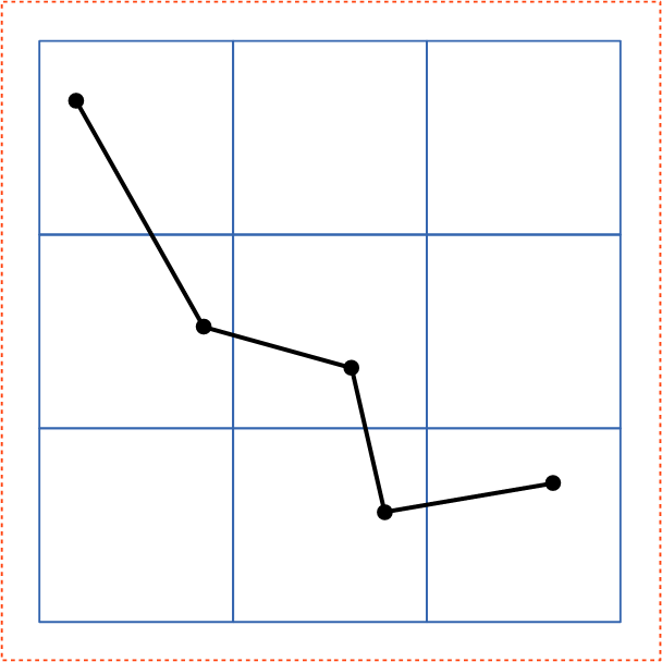
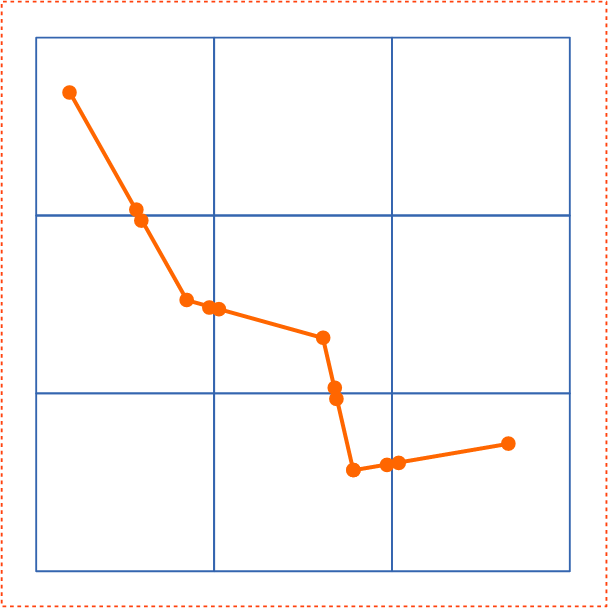
| Before Splitting | After Splitting | |
|---|---|---|
|
|
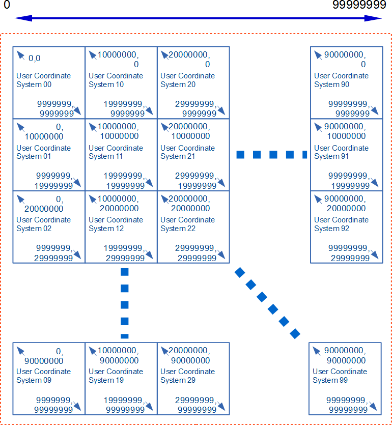
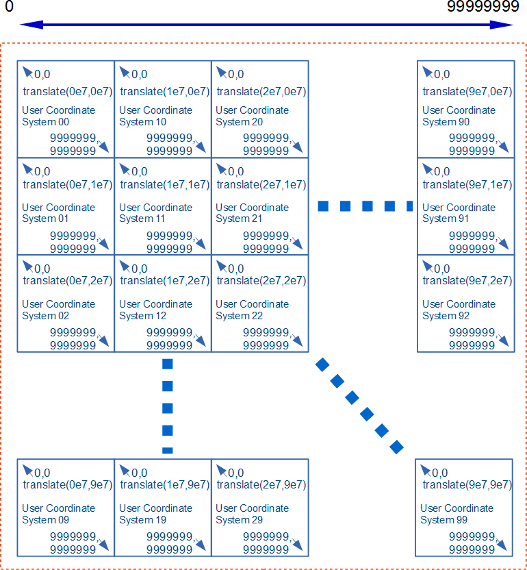
| Step 1 : Splitting content | Step 5 : Arranging tiles with smaller effective digits and appropriate translate | |
|---|---|---|
 |
 |
|
| This example provides the significant figure of eight digits using tiles with the user coordinate system of seven digits. | ||