A graphics element that is defined by some combination of
straight lines and curves. Specifically:
‘circle’, ‘ellipse’, ‘line’, ‘path’, ‘polygon’, ‘polyline’ and ‘rect’.
SVG contains the following set of basic shape elements:
rectangles (including optional rounded corners), created with the ‘rect’ element,
Mathematically, these shape elements are equivalent to a
‘path’ element that would construct the same shape. The basic
shapes may be stroked, filled and used as clip paths. All of the
properties available for ‘path’ elements also apply to the basic
shapes.
The equivalent path and algorithm to compute the stroke for each shape
are defined in the shape sections below.
10.2. The ‘rect’ element
The ‘rect’ element defines a rectangle which is axis-aligned
with the current user coordinate system. Rounded rectangles can be achieved by setting
non-zero values for the rx and ry geometric properties.
The x and y coordinates refer to the left and top edges of the rectangle,
in the current user coordinate system.
The width and height properties define the overall width and height of the rectangle.
A negative value for either property is illegal and must be ignored as a parsing error.
A computed value of zero for either dimension disables rendering of the element.
For rounded rectangles,
the computed values of the rx and ry properties define
the x- and y-axis radii of elliptical arcs used to round off the corners of the rectangle.
The arc are always symmetrical along both horizontal and vertical axis; to create a rectangle with uneven corner rounding, define the shape explicitly with a ‘path’.
A negative value for either property is illegal and must be ignored as a parsing error.
A computed value of zero for either dimension,
or a computed value of auto for both dimensions,
results in a rectangle without corner rounding.
The used values for the x- and y-axis rounded corner radii
may be determined implicitly from the other dimension (using the auto value),
and are also subject to clamping so that the lengths of
the straight segments of the rectangle are never negative.
The used values for rx and ry are determined
from the computed values by following these steps in order:
If both rx and ry have a computed value of auto
(since auto is the initial value for both properties, this will also occur if neither are specified by the author or if all author-supplied values are invalid),
then the used value of both rx and ry is 0. (This will result in square corners.)
Otherwise, convert specified values to absolute values as follows:
If rx is set to a length value or a percentage,
but ry is auto,
calculate an absolute length equivalent for rx, resolving percentages against the used width of the rectangle;
the absolute value for ry is the same.
If ry is set to a length value or a percentage,
but rx is auto,
calculate the absolute length equivalent for ry, resolving percentages against the used height of the rectangle;
the absolute value for rx is the same.
If both rx and ry were set to lengths or percentages,
absolute values are generated individually,
resolving rx percentages against the used width,
and resolving ry percentages against the used height.
Finally, apply clamping to generate the used values:
If the absolute rx (after the above steps)
is greater than half of the used width,
then the used value of rx is half of the used width.
If the absolute ry (after the above steps)
is greater than half of the used height,
then the used value of ry is half of the used height.
Otherwise, the used values of rx and ry are the absolute values computed previously.
Mathematically, a ‘rect’ element is mapped to an
equivalent ‘path’ element as follows,
after generating absolute used values
x, y, width, height,
rx, and rx
in user units for the user coordinate system,
for each of the equivalent geometric properties
following the rules specified above and in Units:
perform an absolute moveto operation to
location (x+rx,y);
perform an absolute horizontal lineto
with parameter x+width-rx;
if both rx and ry are greater than zero,
perform an absolute elliptical arc
operation to coordinate (x+width,y+ry),
where rx and ry are used as the equivalent parameters to
the elliptical arc command,
the x-axis-rotation and large-arc-flag are set to zero,
the sweep-flag is set to one;
perform an absolute vertical lineto
parameter y+height-ry;
if both rx and ry are greater than zero,
perform an absolute elliptical arc
operation to coordinate (x+width-rx,y+height),
using the same parameters as previously;
perform an absolute horizontal lineto
parameter x+rx;
if both rx and ry are greater than zero,
perform an absolute elliptical arc
operation to coordinate (x,y+height-ry),
using the same parameters as previously;
perform an absolute vertical lineto
parameter y+ry
if both rx and ry are greater than zero,
perform an absolute elliptical arc
operation with a segment-completing close path operation,
using the same parameters as previously.
Path decomposition resolved during teleconference on
June
3rd, 2013.
Example rect01 shows a
rectangle with sharp corners. The ‘rect’ element is filled with yellow
and stroked with navy.
<?xml version="1.0" standalone="no"?>
<svg width="12cm" height="4cm" viewBox="0 0 1200 400"
     xmlns="http://www.w3.org/2000/svg" version="1.1">
  <desc>Example rect01 - rectangle with sharp corners</desc>

  <!-- Show outline of viewport using 'rect' element -->
  <rect x="1" y="1" width="1198" height="398"
        fill="none" stroke="blue" stroke-width="2"/>

  <rect x="400" y="100" width="400" height="200"
        fill="yellow" stroke="navy" stroke-width="10"  />
</svg>
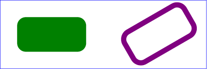
Example rect02 shows
two rounded rectangles. The rx specifies how to round the corners of
the rectangles. Note that since no value has been specified for the ry
attribute, the used value will be derived from the rx attribute.
Mathematically, a ‘circle’ element is mapped to an
equivalent ‘path’ element that consists of four
elliptical
arc segments, each covering a quarter of the circle. The path
begins at the "3 o'clock" point on the radius and proceeds in a
clock-wise direction (before any transformations).
The rx and ry parameters to the arc commands
are both equal to the used value of the r property, after conversion to local user units,
while the x-axis-rotation,
the large-arc-flag,
and the sweep-flag are all set to zero.
The coordinates are computed as follows,
where cx, cy, and r are the used values of the equivalent properties, converted to user units:
The cx and cy coordinates define the center of the ellipse.
The rx and ry properties define the x- and y-axis radii of the
ellipse.
A negative value for either property is illegal and must be ignored as a parsing error.
A computed value of zero for either dimension,
or a computed value of auto for both dimensions,
disables rendering of the element.
An auto value for eitherrx or ry
is converted to a used value, following the rules given above for rectangles
(but without any clamping based on width or height).
Effectively, an auto value creates a circular shape
whose radius is defined by a value expressed solely in one dimension;
this allows for creating a circle with a radius defined in terms of one of the following:
a percentage of the coordinate system width; that is, a percentage value for rx and an auto value for ry.
a percentage of the coordinate system height; that is, an auto value for rx and a percentage value for ry.
New in SVG 2.
The auto value for rx and ry was added to allow consistent
parsing of these properties for both ellipses and rectangles.
Previously, if either rx or ry was unspecified,
the ellipse would not render.
Mathematically, an ‘ellipse’ element is mapped to an
equivalent ‘path’ element that consists of four
elliptical
arc segments, each covering a quarter of the ellipse. The path
begins at the "3 o'clock" point on the radius and proceeds in a
clock-wise direction (before any transformation).
The rx and ry parameters to the arc commands
are the used values of the equivalent properties after conversion to local user units,
while the x-axis-rotation,
the large-arc-flag,
and the sweep-flag are all set to zero.
The coordinates are computed as follows,
where cx, cy, rx, and ry
are the used values of the equivalent properties, converted to user units:
Path decomposition resolved during teleconference on
June
3rd, 2013.
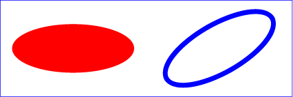
Example ellipse01 below specifies
the coordinates of the two ellipses in the user coordinate system
established by the ‘viewBox’ attribute on the ‘svg’
element and the transform property on the ‘g’ and
‘ellipse’ elements. Both ellipses use the default values of
zero for the cx and cy attributes (the center of the
ellipse). The second ellipse is rotated.
The x- and y-axis coordinates of the end of the line.
A future specification may convert the ‘x1’, ‘y1’, ‘x2’, and ‘y2’ attributes to geometric properties.
Currently, they can only be specified via element attributes, and not CSS.
Mathematically, a ‘line’ element can be mapped to an
equivalent ‘path’ element as follows,
after converting coordinates into user coordinate system user units according
to Units
to generate values x1, y1, x2, and y2:
perform an absolute moveto
operation to absolute location (x1,y1)
perform an absolute lineto
operation to absolute location (x2,y2)
Because ‘line’ elements are single lines and thus are geometrically
one-dimensional, they have no interior; thus, ‘line’ elements are never
filled (see the fill property).
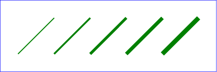
Example line01 below
specifies the coordinates of the five lines in the user coordinate system
established by the ‘viewBox’ attribute on the ‘svg’ element. The
lines have different thicknesses.
The points that make up the polyline. All coordinate
values are in the user coordinate system.
If an odd number of coordinates is provided, then the element is in
error, with the same user agent behavior as occurs with an incorrectly
specified ‘path’ element. In such error cases the user agent will drop
the last, odd coordinate and otherwise render the shape.
The initial value, (none), indicates that the polyline element
is valid but does not render.
A future specification may convert the ‘points’ attribute to a geometric property.
Currently, it can only be specified via an element attribute, and not CSS.
Mathematically, a ‘polyline’ element can be mapped to an
equivalent ‘path’ element as follows:
perform an absolute moveto
operation to the first coordinate pair in the list of points
for each subsequent coordinate pair, perform an absolute
lineto operation to that
coordinate pair.
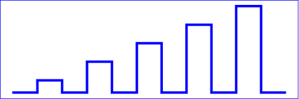
Example polyline01
below specifies a polyline in the user coordinate system established by the
‘viewBox’ attribute on the ‘svg’ element.
The points that make up the polygon. All coordinate
values are in the user coordinate system.
If an odd number of coordinates is provided, then the element is in
error, with the same user agent behavior as occurs with an incorrectly
specified ‘path’ element.
The initial value, (none), indicates that the polygon element
is valid, but does not render.
A future specification may convert the ‘points’ attribute to a geometric property.
Currently, it can only be specified via an element attribute, and not CSS.
Mathematically, a ‘polygon’ element can be mapped to an
equivalent ‘path’ element as follows:
perform an absolute moveto
operation to the first coordinate pair in the list of points
for each subsequent coordinate pair, perform an absolute
lineto operation to that
coordinate pair
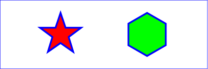
Example
polygon01 below specifies two polygons (a star and a hexagon) in
the user coordinate system established by the ‘viewBox’ attribute
on the ‘svg’ element.
The
x,
y,
width,
height,
rx and
ry IDL attributes
reflect the computed values of the x, y,
width, height, rx and ry
properties and their corresponding presentation attributes,
respectively.
The
cx,
cy and
r IDL attributes
reflect the computed values of the cx, cy
and y properties and their corresponding presentation attributes,
respectively.
The
cx,
cy,
rx and
ry
IDL attributes reflect the computed values of the
cx, cy, rx and ry properties
and their corresponding presentation attributes,
respectively.
The points and
animatedPoints IDL
attributes represent the current non-animated value of the reflected attribute.
On getting points or
animatedPoints,
an SVGPointList object is returned that reflects the base
value of the reflected attribute.
This specification imposes additional requirements on the behaviour of DOMPoint
objects beyond those described in the
Geometry Interfaces
specification, so that they can be used to reflect ‘points’ attributes.
Every DOMPoint object operates in one of three modes.
It can:
reflect an element of the base value of a reflected animatable
attribute (being exposed through the methods on the
points member of
an SVGAnimatedPoints),
represent the current translation of a given ‘svg’ element
(being exposed through the
currentTranslate
member on SVGSVGElement), or
be detached, which is the case for DOMPoint objects created
using their constructor or with
createSVGPoint.
A DOMPoint object can be associated
with a particular element. The associated element is used to
determine which element's content attribute to update if the object reflects
an attribute. Unless otherwise described, a DOMPoint object is not
associated with any element.
A DOMPoint object can be designated as read only,
which means that attempts to modify the object will result in an exception
being thrown. When assigning to a read only DOMPoint's
x,
y,
w or
z
IDL attribute, a NoModificationAllowedError must be
thrown instead of updating the internal coordinate value.
Note that this applies only to the read-write DOMPoint
interface; the DOMPointReadOnly interface, which is not used for reflecting
the ‘points’ attribute, will already throw an exception if
an attempt is made to modify it.
When assigning to a writable DOMPoint's
x,
y,
w or
z
IDL attribute, the following steps are run after updating
the internal coordinate value:

