'path' elements, 'text' elements and basic shapes can be filled (which means painting the interior of the object) and stroked (which means painting along the outline of the object). Filling and stroking both can be thought of in more general terms as painting operations.
Certain elements (i.e., 'path', 'polyline', 'polygon' and 'line' elements) can also have marker symbols drawn at their vertices.
With SVG, you can paint (i.e., fill or stroke) with:
SVG uses the general notion of a paint server. Paint servers are specified using a URI reference on a 'fill' or 'stroke' property. Gradients and patterns are just specific types of paint servers.
Properties 'fill' and 'stroke' take on a value of type <paint>, which is specified as follows:
| <paint>: | none | currentColor | <color> [icc-color(<name>,<icccolorvalue>+)] | <uri> [ none | currentColor | <color> [icc-color(<name>,<icccolorvalue>+)]] | inherit |
| Value: | <paint> (See Specifying paint) |
| Initial: | black |
| Applies to: | all elements |
| Inherited: | see Inheritance of Painting Properties below |
| Percentages: | N/A |
| Media: | visual |
| Animatable: | yes |
The 'fill' property paints the interior of the given graphical element. The area to be painted consists of any areas inside the outline of the shape. To determine the inside of the shape, all subpaths are considered, and the interior is determined according to the rules associated with the current value of the 'fill-rule' property. The zero-width geometric outline of a shape is included in the area to be painted.
The fill operation automatically closes all open subpaths by connecting the last point of the subpath with the first point of the subpath before painting the fill. Thus, fill operations apply to both open subpaths within 'path' elements (i.e., subpaths without a closepath command) and 'polyline' elements.
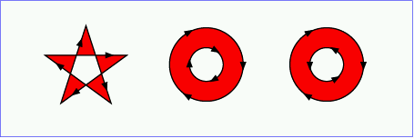
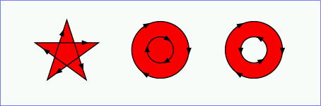
.| Value: | evenodd | nonzero | inherit |
| Initial: | evenodd |
| Applies to: | all elements |
| Inherited: | yes |
| Percentages: | N/A |
| Media: | visual |
| Animatable: | yes |
The 'fill-rule' property indicates the algorithm which is to be used to determine what parts of the canvas are included inside the shape. For a simple, non-intersecting path, it is intuitively clear what region lies "inside"; however, for a more complex path, such as a path that intersects itself or where one subpath encloses another, the interpretation of "inside" is not so obvious.
The 'fill-rule' property provides two options for how the inside of a shape is determined:
(Note: the above explanations do not specify what to do if a path segment coincides with or is tangent to the ray. Since any ray will do, one may simply choose a different array that does not have such problem intersections.)
Here are examples which illustrate the two rules:
| Value: | <opacity-value> | inherit |
| Initial: | 1 |
| Applies to: | all elements |
| Inherited: | yes |
| Percentages: | N/A |
| Media: | visual |
| Animatable: | yes |
'fill-opacity' specifies the opacity of the painting operation used to paint the interior the current object. (See Painting shapes and text.)
Related properties: 'stroke-opacity' and 'opacity'.
The following are the properties which affect how an element is stroked.
In all cases, all stroking properties which are affected by directionality, such as those having to do with dash patterns, must be rendered such that the stroke operation starts at the same point at which the graphics element starts. In particular, for 'path' elements, the start of the path is the first point of the initial "moveto" command.
For stroking properties such as dash patterns whose computations are dependent on progress along the outline of the graphics element, distance calculations are required to utilize the SVG user agent's standard Distance along a path algorithms.
When stroking is performed using a complex paint server, such as a gradient or a pattern, the stroke operation must be identical to the result that would have occurred if the geometric shape defined by the geometry of the current graphics element and its associated stroking properties were converted to an equivalent 'path' element and then filled using the given paint server.
| Value: | <paint> (See Specifying paint) |
| Initial: | none |
| Applies to: | all elements |
| Inherited: | see Inheritance of Painting Properties below |
| Percentages: | N/A |
| Media: | visual |
| Animatable: | yes |
The 'stroke' property paints along the outline of the given graphical element.
A subpath (see Paths) consisting of a single moveto is not stroked. A subpath consisting of a moveto and lineto to the same exact location or a subpath consisting of a moveto and a closepath will be stroked only if the 'stroke-linecap' property is set to "round", producing a circle centered at the given point.
| Value: | <width> | inherit |
| Initial: | 1 |
| Applies to: | all elements |
| Inherited: | yes |
| Percentages: | Yes |
| Media: | visual |
| Animatable: | yes |
| Value: | butt | round | square | inherit |
| Initial: | butt |
| Applies to: | all elements |
| Inherited: | yes |
| Percentages: | N/A |
| Media: | visual |
| Animatable: | yes |
'stroke-linecap' specifies the shape to be used at the end of open subpaths when they are stroked.
| Value: | miter | round | bevel | inherit |
| Initial: | miter |
| Applies to: | all elements |
| Inherited: | yes |
| Percentages: | N/A |
| Media: | visual |
| Animatable: | yes |
'stroke-linejoin' specifies the shape to be used at the corners of paths (or other vector shapes) that are stroked. when they are stroked.
| Value: | <miterlimit> | inherit |
| Initial: | 4 |
| Applies to: | all elements |
| Inherited: | yes |
| Percentages: | N/A |
| Media: | visual |
| Animatable: | yes |
When two line segments meet at a sharp angle and miter joins have been specified for 'stroke-linejoin', it is possible for the miter to extend far beyond the thickness of the line stroking the path. The 'stroke-miterlimit' imposes a limit on the ratio of the miter length to the 'stroke-linewidth'.
| Value: | none | <dasharray> | inherit |
| Initial: | none |
| Applies to: | all elements |
| Inherited: | yes |
| Percentages: | yes (see below) |
| Media: | visual |
| Animatable: | yes (non-additive) |
'stroke-dasharray' controls the pattern of dashes and gaps used to stroke paths. <dasharray> contains a list of comma-separated (with optional white space) <number>s that specify the lengths of alternating dashes and gaps in user units. If an odd number of values is provided, then the list of values is repeated to yield an even number of values. Thus, stroke-dasharray: 5 3 2 is equivalent to stroke-dasharray: 5 3 2 5 3 2.
| Value: | <dashoffset> | inherit |
| Initial: | 0 |
| Applies to: | all elements |
| Inherited: | yes |
| Percentages: | see prose |
| Media: | visual |
| Animatable: | yes |
'stroke-dashoffset' specifies the distance into the dash pattern to start the dash.
| Value: | <opacity-value> | inherit |
| Initial: | 1 |
| Applies to: | all elements |
| Inherited: | yes |
| Percentages: | N/A |
| Media: | visual |
| Animatable: | yes |
'stroke-opacity' specifies the opacity of the painting operation used to stroke the current object. (See Painting shapes and text.)
Related properties: 'fill-opacity' and 'opacity'.
SVG uses two properties, 'display' and 'visibility', to control the visibility of graphical content. Either property can make an element invisible.
The differences between the two properties are as follows:
| Value: | inline | block | list-item | run-in | compact | marker | table | inline-table | table-row-group | table-header-group | table-footer-group | table-row | table-column-group | table-column | table-cell | table-caption | none | inherit |
| Initial: | inline |
| Applies to: | all elements |
| Inherited: | no |
| Percentages: | N/A |
| Media: | all |
| Animatable: | yes |
A value of display: none indicates that the given element and its children shall not be rendered (i.e., document rendering occurs as if the given element and its children were not part of the document). Any value other than none or inherit indicates that the given element shall be rendered by the SVG user agent.
Except for any additional information provided in this specification, the normative definition of the property is in [CSS2].
| Value: | visible | hidden | collapse | inherit |
| Initial: | inherit |
| Applies to: | all elements |
| Inherited: | no |
| Percentages: | N/A |
| Media: | visual |
| Animatable: | yes |
Note that if the 'visibility' property is set to hidden on a 'tspan', 'tref' or 'glyphRun' element, then the text is invisible but still takes up space in calculations of text layout.
Depending on the value of property 'pointer-events', graphics elements which have their 'visibility' property set to hidden still might receive events.
Except for any additional information provided in this specification, the normative definition of the property is in [CSS2].
To use a marker symbol for arrowheads or polymarkers, you need to define a 'marker' element which defines the marker symbol and then refer to that 'marker' element using the various marker properties (i.e., 'marker-start', 'marker-end', 'marker-mid' or 'marker') on the given 'path' element or vector graphic shape. Here is an example which draws a triangular marker symbol that is drawn as an arrowhead at the end of a path:
<?xml version="1.0" standalone="no"?>
<!DOCTYPE svg PUBLIC "-//W3C//DTD SVG 20000629//EN"
  "http://www.w3.org/TR/2000/WD-SVG-20000629/DTD/svg-20000629.dtd">
<svg width="4in" height="3in"
     viewBox="0 0 4000 3000" >
  <defs>
    <marker id="Triangle"
      viewBox="0 0 10 10" refX="0" refY="5"
      markerUnits="strokeWidth"
      markerWidth="2" markerHeight="3"
      orient="auto">
      <path d="M 0 0 L 10 5 L 0 10 z" />
    </marker>
  </defs>
  <desc>Placing an arrowhead at the end of a path.
  </desc>
  <path d="M 1000 1000 L 2000 1000 L 2500 1500"
        style="fill:none; stroke:black; stroke-width:100;
        marker-end:url(#Triangle)" />
</svg>
View this example as SVG (SVG-enabled browsers only)
The 'marker'
element defines the graphics that is to be used for drawing arrowheads
or polymarkers on a given 'path' element or vector graphic shape.
<!ENTITY % markerExt "" > <!ELEMENT marker (desc|title|metadata|defs| path|text|rect|circle|ellipse|line|polyline|polygon| use|image|svg|g|view|switch|a|altGlyphDef| script|style|symbol|marker|clipPath|mask| linearGradient|radialGradient|pattern|filter|cursor|font| animate|set|animateMotion|animateColor|animateTransform| color-profile|font-face %ceExt;%markerExt;)* > <!ATTLIST marker %stdAttrs; %langSpaceAttrs; externalResourcesRequired %Boolean; #IMPLIED class %ClassList; #IMPLIED style %StyleSheet; #IMPLIED %PresentationAttributes-All; viewBox %ViewBoxSpec; #IMPLIED preserveAspectRatio %PreserveAspectRatioSpec; 'xMidYMid meet' refX %Coordinate; #IMPLIED refY %Coordinate; #IMPLIED markerUnits (strokeWidth | userSpaceOnUse | userSpace) #IMPLIED markerWidth %Length; #IMPLIED markerHeight %Length; #IMPLIED orient CDATA #IMPLIED > |
Attribute definitions:
Markers are drawn such that their reference point (i.e., attributes refX and refY) is positioned at the given vertex.
'marker-start' defines the arrowhead or polymarker that shall be drawn at the first vertex of the given 'path' element or vector graphic shape. 'marker-end' defines the arrowhead or polymarker that shall be drawn at the final vertex. 'marker-mid' defines the arrowhead or polymarker that shall be drawn at every other vertex (i.e., every vertex except the first and last).
| Value: | none | inherit | <uri> |
| Initial: | none |
| Applies to: | 'path', 'line', 'polyline' and 'polygon' elements |
| Inherited: | see Inheritance of Painting Properties below |
| Percentages: | N/A |
| Media: | visual |
| Animatable: | yes |
The 'marker' property specifies the marker symbol that shall be used for all points on the sets the value for all vertices on the given 'path' element or vector graphic shape. It is a short-hand for the three individual marker properties:
| Value: | see individual properties |
| Initial: | see individual properties |
| Applies to: | 'path', 'line', 'polyline' and 'polygon' elements |
| Inherited: | see Inheritance of Painting Properties below |
| Percentages: | N/A |
| Media: | visual |
| Animatable: | yes |
Markers are drawn after the given object is filled and stroked.
Each marker is drawn into a temporary viewport. The temporary viewport and its associated temporary viewport coordinate system are such that:
For illustrative purposes, we'll repeat the marker example shown earlier:
<?xml version="1.0" standalone="no"?>
<!DOCTYPE svg PUBLIC "-//W3C//DTD SVG 20000629//EN"
  "http://www.w3.org/TR/2000/WD-SVG-20000629/DTD/svg-20000629.dtd">
<svg width="4in" height="3in"
     viewBox="0 0 4000 3000" >
  <defs>
    <marker id="Triangle"
      viewBox="0 0 10 10" refX="0" refY="5"
      markerUnits="strokeWidth"
      markerWidth="2" markerHeight="3"
      orient="auto">
      <path d="M 0 0 L 10 5 L 0 10 z" />
    </marker>
  </defs>
  <desc>Placing an arrowhead at the end of a path.
  </desc>
  <path d="M 1000 1000 L 2000 1000 L 2500 1500"
        style="fill:none; stroke:black; stroke-width:100;
        marker-end:url(#Triangle)" />
</svg>
View this example as SVG (SVG-enabled browsers only)
The rendering effect of the above file will be visually identical to the following:
<?xml version="1.0" standalone="no"?>
<!DOCTYPE svg PUBLIC "-//W3C//DTD SVG 20000629//EN"
  "http://www.w3.org/TR/2000/WD-SVG-20000629/DTD/svg-20000629.dtd">
<svg width="4in" height="3in"
     viewBox="0 0 4000 3000" >

  <desc>File which produces the same effect
      as the marker example file, but without
      using markers.
  </desc>
  <!-- The path draws as before, but without the marker properties -->
  <path d="M 1000 1000 L 2000 1000 L 2500 1500"
        style="fill:none; stroke:black; stroke-width:100" />

  <!-- The following logic simulates drawing a marker
       at final vertex of the path. -->

  <!-- First off, move the origin of the user coordinate system
       so that the origin is now aligned with the end point of the path. -->
  <g transform="translate(2500,1500)" >

    <!-- Now, rotate the coordinate system 45 degrees because
         the marker specified orient="auto" and the final segment
         of the path is going in the direction of 45 degrees. -->
    <g transform="rotate(45)" >

      <!-- Now, scale the coordinate system by the current value of
           the 'stroke-width' property, which is 100. -->
      <g transform="scale(100)" >

        <!-- Now, translate the coordinate system by
             (-markerWidth * refX / viewBoxWidth, -markerHeight * refY / viewBoxHeight)
             so that (refX,refY) within the marker will align with the vertex.
             Since refX is zero, there is no horizontal translation.
             Since markerWidth is 3, refY is 5 and height of the viewBox is 10,
             translate in Y by -3*5/10 = -1.5 -->
        <g transform="translate(0,-1.5)" >

          <!-- Establish a new viewport with an 'svg' element.
               The width/height of the viewport are 2 and 3 times
               the current stroke-width. -->
          <svg width="2" height="3" viewBox="0 0 10 10"" >

            <!-- Expand out the contents of the 'marker' element. -->
            <path d="M 0 0 L 10 5 L 0 10 z" />
          </svg>
        </g>
      </g>
    </g>
  </g>
</svg>
View this example as SVG (SVG-enabled browsers only)
The SVG user agent performs color interpolations and compositing in the following cases:
The 'color-interpolation' property specifies whether color interpolations and compositing shall be performed in the sRGB [SRGB] color space or in a (light energy linear) linearized RGB color space.
The conversion formulas between sRGB color space and linearized RGB color space is can be found in [SRGB]. The following formula shows the conversion from sRGB to linearized RGB:
  R'[sRGB] = R[sRGB] / 255
  G'[sRGB] = G[sRGB] / 255
  B'[sRGB] = B[sRGB] / 255

If R'[sRGB], G'[sRGB], B'[sRGB] <= 0.04045

  R[linearRGB] = R'[sRGB] / 12.92
  G[linearRGB] = G'[sRGB] / 12.92
  B[linearRGB] = B'[sRGB] / 12.92

else if R'[sRGB], G'[sRGB], B'[sRGB] > 0.04045

  R[linearRGB] = ((R'[sRGB] + 0.055) / 1.055) ^ 2.4
  G[linearRGB] = ((G'[sRGB] + 0.055) / 1.055) ^ 2.4
  B[linearRGB] = ((B'[sRGB] + 0.055) / 1.055) ^ 2.4
Out-of-range color values, if supported by the user agent, also are converted using the above formulas. (See Clamping values which are restricted to a particular range.)
| Value: | auto | sRGB | linearRGB | inherit |
| Initial: | sRGB |
| Applies to: | color interpolation and compositing operations |
| Inherited: | yes |
| Percentages: | N/A |
| Media: | visual |
| Animatable: | yes |
The creator of SVG content might want to provide a hint to the implementation about how to make speed vs. quality tradeoffs as it performs color interpolation and compositing. The 'color-rendering' property provides a hint to the SVG user agent about how to optimize its color interpolation and compositing operations:
| Value: | auto | optimizeSpeed | optimizeQuality | inherit |
| Initial: | auto |
| Applies to: | color interpolation and compositing operations |
| Inherited: | yes |
| Percentages: | N/A |
| Media: | visual |
| Animatable: | yes |
The creator of SVG content might want to provide a hint to the implementation about what tradeoffs to make as it renders vector graphics elements such as 'path' elements and basic shapes such as circles and rectangles. The 'shape-rendering' property provides these hints.
| Value: | auto | optimizeSpeed | crispEdges | geometricPrecision | inherit |
| Initial: | auto |
| Applies to: | all elements |
| Inherited: | yes |
| Percentages: | N/A |
| Media: | visual |
| Animatable: | yes |
The creator of SVG content might want to provide a hint to the implementation about what tradeoffs to make as it renders text. The 'text-rendering' property provides these hints.
| Value: | auto | optimizeSpeed | optimizeLegibility | geometricPrecision | inherit |
| Initial: | auto |
| Applies to: | 'text' elements |
| Inherited: | yes |
| Percentages: | N/A |
| Media: | visual |
| Animatable: | yes |
The creator of SVG content might want to provide a hint to the implementation about how to make speed vs. quality tradeoffs as it performs image processing. The 'image-rendering' property provides a hint to the SVG user agent about how to optimize its image rendering.:
| Value: | auto | optimizeSpeed | optimizeQuality | inherit |
| Initial: | auto |
| Applies to: | images |
| Inherited: | yes |
| Percentages: | N/A |
| Media: | visual |
| Animatable: | yes |
The values of any of the painting properties described in this chapter can be inherited from a given object's parent. Painting, however, is always done on each leaf-node individually, never at the 'g' level. Thus, for the following SVG, even though the gradient fill is specified on the 'g', the gradient is simply inherited through the 'g' element down into each rectangle, each of which is rendered such that its interior is painted with the gradient.
<?xml version="1.0" standalone="no"?>
<!DOCTYPE svg PUBLIC "-//W3C//DTD SVG 20000629//EN"
  "http://www.w3.org/TR/2000/WD-SVG-20000629/DTD/svg-20000629.dtd">
<svg width="7cm" height="2cm">
  <desc>Gradients apply to leaf nodes
  </desc>
  <g>
    <defs>
      <linearGradient id="MyGradient" gradientUnits="objectBoundingBox">
        <stop offset="0%" style="stop-color:#F60"/>
        <stop offset="100%" style="stop-color:#FF6"/>
      </linearGradient>
    </defs>
    <g style="fill:url(#MyGradient)">
      <rect x="1cm" y="1cm" width="2cm" height="1cm"/>
      <rect x="4cm" y="1cm" width="2cm" height="1cm"/>
   </g>
  </g>
</svg>
View this example as SVG (SVG-enabled browsers only)
The following interfaces are defined below: SVGPaint, SVGMarkerElement.
The SVGPaint interface corresponds to basic type <paint> and represents the values of properties 'fill' and 'stroke'.
interface SVGPaint : SVGColor {
  // Paint Types
  const unsigned short SVG_PAINTTYPE_UNKNOWN               = 0;
  const unsigned short SVG_PAINTTYPE_RGBCOLOR              = 1;
  const unsigned short SVG_PAINTTYPE_RGBCOLOR_ICCCOLOR     = 2;
  const unsigned short SVG_PAINTTYPE_NONE                  = 101;
  const unsigned short SVG_PAINTTYPE_CURRENTCOLOR          = 102;
  const unsigned short SVG_PAINTTYPE_URI_NONE              = 103;
  const unsigned short SVG_PAINTTYPE_URI_CURRENTCOLOR      = 104;
  const unsigned short SVG_PAINTTYPE_URI_RGBCOLOR          = 105;
  const unsigned short SVG_PAINTTYPE_URI_RGBCOLOR_ICCCOLOR = 106;

  readonly attribute unsigned short paintType;
  readonly attribute DOMString      uri;

  void setUri ( in DOMString uri );
  void setPaint ( in unsigned short paintType, in DOMString uri, in css::RGBColor rgbColor, in SVGICCColor iccColor );
};
| SVG_PAINTTYPE_UNKNOWN | The paint type is not one of predefined types. It is invalid to attempt to define a new value of this type or to attempt to switch an existing value to this type. | |
| SVG_PAINTTYPE_RGBCOLOR | An sRGB color has been specified without an alternative ICC color specification. | |
| SVG_PAINTTYPE_RGBCOLOR_ICCCOLOR | An sRGB color has been specified along with an alternative ICC color specification. | |
| SVG_PAINTTYPE_NONE | Corresponds to a 'none' value on a <paint> specification. | |
| SVG_PAINTTYPE_CURRENTCOLOR | Corresponds to a 'currentColor' value on a <paint> specification. | |
| SVG_PAINTTYPE_URI_NONE | A URI has been specified, along with either an explicit or an implicit 'none' as the backup paint method in case the URI is unavailable or invalid. | |
| SVG_PAINTTYPE_URI_CURRENTCOLOR | A URI has been specified, along with 'currentColor' as the backup paint method in case the URI is unavailable or invalid. | |
| SVG_PAINTTYPE_URI_RGBCOLOR | A URI has been specified, along with an sRGB color as the backup paint method in case the URI is unavailable or invalid. | |
| SVG_PAINTTYPE_URI_RGBCOLOR_ICCCOLOR | A URI has been specified, along with both an sRGB color and alternate ICC color as the backup paint method in case the URI is unavailable or invalid. |
| in DOMString uri | The URI for the desired paint server. |
paintType requires a URI, then uri must be non-null and a valid string;
otherwise, uri must be null.
If paintType requires an RGBColor, then rgbColor must be a valid RGBColor object;
otherwise, rgbColor must be null.
If paintType requires an SVGICCColor, then iccColor must be a valid SVGICCColor object;
otherwise, iccColor must be null.
| in unsigned short paintType | One of the defined constants for paintType. | |
| in DOMString uri | The URI for the desired paint server, or null. | |
| in css::RGBColor rgbColor | The specification of an sRGB color, or null. | |
| in SVGICCColor iccColor | The specification of an ICC color, or null. |
The SVGMarkerElement interface corresponds to the 'marker' element.
interface SVGMarkerElement :
                SVGElement,
                SVGLangSpace,
                SVGExternalResourcesRequired,
                SVGStylable,
                SVGFitToViewBox {

  // Marker Unit Types
  const unsigned short SVG_MARKERUNITS_UNKNOWN        = 0;
  const unsigned short SVG_MARKERUNITS_USERSPACEONUSE = 1;
  const unsigned short SVG_MARKERUNITS_USERSPACE      = 2;
  const unsigned short SVG_MARKERUNITS_STROKEWIDTH    = 3;
  // Marker Orientation Types
  const unsigned short SVG_MARKER_ORIENT_UNKNOWN      = 0;
  const unsigned short SVG_MARKER_ORIENT_AUTO         = 1;
  const unsigned short SVG_MARKER_ORIENT_ANGLE        = 2;

           attribute SVGAnimatedLength      refX;
                       // raises DOMException on setting
           attribute SVGAnimatedLength      refY;
                       // raises DOMException on setting
           attribute SVGAnimatedEnumeration markerUnits;
                       // raises DOMException on setting
           attribute SVGAnimatedLength      markerWidth;
                       // raises DOMException on setting
           attribute SVGAnimatedLength      markerHeight;
                       // raises DOMException on setting
  readonly attribute SVGAnimatedEnumeration orientType;
  readonly attribute SVGAnimatedAngle      orientAngle;

  void setOrientToAuto (  );
  void setOrientToAngle ( in SVGAngle angle );
};
| SVG_MARKERUNITS_UNKNOWN | The marker unit type is not one of predefined types. It is invalid to attempt to define a new value of this type or to attempt to switch an existing value to this type. | |
| SVG_MARKERUNITS_USERSPACEONUSE | The value of attribute markerUnits is 'userSpaceOnUse'. | |
| SVG_MARKERUNITS_USERSPACE | The value of attribute markerUnits is 'userSpace'. | |
| SVG_MARKERUNITS_STROKEWIDTH | The value of attribute markerUnits is 'strokeWidth'. |
| SVG_MARKER_ORIENT_UNKNOWN | The marker orientation is not one of predefined types. It is invalid to attempt to define a new value of this type or to attempt to switch an existing value to this type. | |
| SVG_MARKER_ORIENT_AUTO | Attribute orient has value 'auto'. | |
| SVG_MARKER_ORIENT_ANGLE | Attribute orient has an angle value. |
| DOMException |
NO_MODIFICATION_ALLOWED_ERR: Raised when the node is readonly.
|
| DOMException |
NO_MODIFICATION_ALLOWED_ERR: Raised when the node is readonly.
|
| DOMException |
NO_MODIFICATION_ALLOWED_ERR: Raised when the node is readonly.
|
| DOMException |
NO_MODIFICATION_ALLOWED_ERR: Raised when the node is readonly.
|
| DOMException |
NO_MODIFICATION_ALLOWED_ERR: Raised when the node is readonly.
|
| in SVGAngle angle | The angle value to use for attribute orient. |