8 Paths
Contents
8.1 Introduction
Paths represent the outline of a shape which can be filled or
stroked. (See Filling, Stroking and Paint
Servers.)
A path is described using the concept of a current point. In
an analogy with drawing on paper, the current point can be
thought of as the location of the pen. The position of the pen
can be changed, and the outline of a shape (open or closed) can
be traced by dragging the pen in either straight lines or
curves.
Paths represent the geometry of the outline of an object,
defined in terms of moveto (set a new current point),
lineto (draw a straight line), curveto (draw
a curve using a cubic Bézier) and closepath (close the current
shape by drawing a line to the last moveto) elements.
Compound paths (i.e., a path with multiple subpaths) are
possible to allow effects such as "donut holes" in objects.
This chapter describes the syntax and behavior for SVG paths.
Various implementation notes for SVG
paths can be found in 'path' element implementation
notes.
A path is defined in SVG using the 'path' element.
8.2 The 'path'
element
8.2.1 Animating path data
Interpolated path data animation is only possible when each normalized path data specification within an animation specification has exactly the same list of path data commands as the 'd' attribute after normalization. This means that each path data specification and the 'd' attribute would have the exact same list of commands if normalized as defined in Path Normalization. If an animation is specified and the list of path data commands is not the same, then the animation specification must be ignored as unsupported. The animation engine shall interpolate each parameter to each path data command separately based upon the attributes on the given animation element.
Non-interpolated (i.e. calcMode="discrete") path data animation is always possible.
8.3 Path data
A path is defined by including a 'path' element which contains a 'd' attribute, where the 'd' attribute contains the moveto, line, curve (both cubic and quadratic Béziers) and closepath instructions.
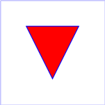
Example 08_01 specifies a 'path' in the shape of a triangle. (The M indicates a moveto, the L's indicate lineto's, and the z indicates a closepath).
<?xml version="1.0"?>
<svg width="4cm" height="4cm" viewBox="0 0 400 400"
     xmlns="http://www.w3.org/2000/svg" version="1.2" baseProfile="tiny">
  <title>Example triangle01- simple example of a 'path'</title>
  <desc>A path that draws a triangle</desc>
  <rect x="1" y="1" width="398" height="398"
        fill="none" stroke="blue" />
  <path d="M 100 100 L 300 100 L 200 300 z"
        fill="red" stroke="blue" stroke-width="3" />
</svg>
Path data can contain newline characters and thus can be
broken up into multiple lines to improve readability.
The syntax of path data is concise in order to allow for
minimal file size and efficient downloads, since many SVG files
will be dominated by their path data. Some of the ways that SVG
attempts to minimize the size of path data are as follows:
All instructions are expressed as one character (e.g., a moveto is expressed as an M).
Superfluous white space and separators such as commas can be eliminated (e.g., 'M 100 100 L 200 200' contains unnecessary spaces and could be expressed more compactly as 'M100 100L200 200').
The command letter can be eliminated on subsequent commands if the same command is used multiple times in a row (e.g., you can drop the second "L" in 'M 100 200 L 200 100 L -100 -200' and use 'M 100 200 L 200 100 -100 -200' instead).
Relative versions of all commands are available (uppercase means absolute coordinates, lowercase means relative coordinates).
Alternate forms of lineto are available to optimize the special cases of horizontal and vertical lines (absolute and relative).
Alternate forms of curve are available to optimize the special cases where some of the control points on the current segment can be determined automatically from the control points on the previous segment.
The path data syntax is a prefix notation (i.e., commands
followed by parameters). The only allowable decimal point is a
Unicode U+002E
FULL STOP (".") character (also referred to in Unicode as
PERIOD, dot and decimal point) [UNICODE] and no other delimiter
characters are allowed. (For example, the following is an
invalid numeric value in path data: "13,000.56".
Instead, say: "13000.56".)
For the relative versions of the commands, all coordinate values shall be relative to the current point at the start of the command.
In the tables below, the following notation is used:
- (): grouping of parameters
- +: 1 or more of the given parameter(s) is required
- Coordinates following commands in uppercase (e.g., M) shall be treated as absolute coordinates.
- Coordinates following commands in lowercase (e.g., m) shall be treated as relative coordinates.
The following sections list the commands.
8.3.2 The "moveto" commands
The 'moveto' commands (M or m) establish a new current point. The effect is as if the "pen" were lifted and moved to a new location. A path data segment (if there is one) must begin with a 'moveto' command. Subsequent 'moveto' commands (i.e., when the 'moveto' is not the first command) represent the start of a new subpath:
| Command |
Name |
Parameters |
Description |
M (absolute)
m (relative) |
moveto |
(x y)+ |
A new sub-path at the given (x,y) coordinate shall be started. This shall also establish a new current point at the given coordinate. If a relative 'moveto' (m) appears as the first element of the 'path', then it shall treated as a pair of absolute coordinates. If a 'moveto' is followed by multiple pairs of coordinates, the subsequent pairs shall be treated as implicit 'lineto' commands. |
8.3.3 The "closepath" command
A straight line shall be drawn from the current point to the initial point of the current subpath, and shall end the current subpath. If a 'closepath' (Z or z) is followed immediately by any other command, then the next subpath must start at the same initial point as the current subpath.
When a subpath ends in a 'closepath', it differs in behavior from what happens when "manually" closing a subpath via a 'lineto' command in how 'stroke-linejoin' and 'stroke-linecap' are implemented. With 'closepath', the end of the final segment of the subpath shall be "joined" with the start of the initial segment of the subpath using the current value of 'stroke-linejoin'. If instead the subpath is closed "manually" via a 'lineto' command, the start of the first segment and the end of the last segment are not joined but instead shall each be capped using the current value of 'stroke-linecap'. At the end of the command, the new current point shall be set to the initial point of the current subpath.
| Command |
Name |
Parameters |
Description |
Z or
z |
closepath |
(none) |
The current subpath shall be closed by drawing a straight line from
the current point to current subpath's initial point, which then shall
become the new current point. Since the Z and z commands take no
parameters, they have an identical effect.
|
8.3.4 The "lineto" commands
The various 'lineto' commands draw straight lines from the
current point to a new point:
| Command |
Name |
Parameters |
Description |
L (absolute)
l (relative) |
lineto |
(x y)+ |
A line shall be drawn from the current point to the given (x,y) coordinate, which then shall become the new current point. If more than one coordinate pair is specified, a polyline shall be drawn. At the end of the command, the new current point shall be set to the final set of coordinates provided. |
H (absolute)
h (relative) |
horizontal lineto |
x+ |
A horizontal line shall be drawn from the current point (cpx, cpy) to (x, cpy). If more than one x value is specified, multiple horizonal lines shall be drawn (although usually this doesn't make sense). At the end of the command, the new current point shall be (x, cpy) for the final value of x. |
V (absolute)
v (relative) |
vertical lineto |
y+ |
A vertical line shall be drawn from the current point (cpx, cpy) to (cpx, y). If more than one y value is specified, multiple vertical lines shall be drawn (although usually this doesn't make sense). At the end of the command, the new current point shall be (cpx, y) for the final value of y. |
8.3.5 The Curve commands
These groups of commands draw curves:
- Cubic
Bézier commands (C,
c, S and
s). A cubic Bézier segment is defined
by a start point, an end point, and two control points.
- Quadratic
Bézier commands (Q,
q, T and
t). A quadratic Bézier segment is
defined by a start point, an end point, and one control
point.
8.3.6 The Cubic Bézier curve commands
The 'Cubic Bézier' commands are as follows:
| Command |
Name |
Parameters |
Description |
C (absolute)
c (relative) |
curveto |
(x1 y1 x2 y2 x y)+ |
A cubic Bézier curve shall be drawn from the current point to (x,y) using (x1,y1) as the control point at the beginning of the curve and (x2,y2) as the control point at the end of the curve. If multiple sets of coordinates are specified, a polybézier shall be drawn. At the end of the command, the new current point shall be the final (x,y) coordinate pair used in the polybézier. |
S (absolute)
s (relative) |
shorthand/smooth curveto |
(x2 y2 x y)+ |
A cubic Bézier curve shall be drawn from the current point to (x,y). The first control point shall be the reflection of the second control point on the previous command relative to the current point. (If there is no previous command or if the previous command was not an C, c, S or s, the first control point shall be coincident with the current point.) (x2,y2) shall be used as the second control point (i.e., the control point at the end of the curve). If multiple sets of coordinates are specified, a polybézier shall be drawn. At the end of the command, the new current point shall be the final (x,y) coordinate pair used in the polybézier. |
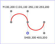
Example 08_02 shows some
simple uses of 'Cubic Bézier' commands within a 'path'. Note that the control point for the "S" command is
computed automatically as the reflection of the control point
for the previous "C" command relative to the start point of the
"S" command.
<?xml version="1.0"?>
<svg width="5cm" height="4cm" viewBox="0 0 500 400"
     xmlns="http://www.w3.org/2000/svg" version="1.2" baseProfile="tiny">
  <title>Example cubic01- cubic Bézier commands in path data</title>
  <desc>Picture showing a simple example of path data
        using both a "C" and an "S" command,
        along with annotations showing the control points
        and end points</desc>
  <rect fill="none" stroke="blue" stroke-width="1" x="1" y="1" width="498" height="398" />
  <polyline fill="none" stroke="#888888" stroke-width="1" points="100,200 100,100" />
  <polyline fill="none" stroke="#888888" stroke-width="1" points="250,100 250,200" />
  <polyline fill="none" stroke="#888888" stroke-width="1" points="250,200 250,300" />
  <polyline fill="none" stroke="#888888" stroke-width="1" points="400,300 400,200" />
  <path fill="none" stroke="red" stroke-width="5" d="M100,200 C100,100 250,100 250,200
                                       S400,300 400,200" />
  <circle fill="#888888" stroke="none" stroke-width="2" cx="100" cy="200" r="10" />
  <circle fill="#888888" stroke="none" stroke-width="2" cx="250" cy="200" r="10" />
  <circle fill="#888888" stroke="none" stroke-width="2" cx="400" cy="200" r="10" />
  <circle fill="#888888" stroke="none" cx="100" cy="100" r="10" />
  <circle fill="#888888" stroke="none" cx="250" cy="100" r="10" />
  <circle fill="#888888" stroke="none" cx="400" cy="300" r="10" />
  <circle fill="none" stroke="blue" stroke-width="4" cx="250" cy="300" r="9" />
  <text font-size="22" font-family="Verdana" x="25" y="70">M100,200 C100,100 250,100 250,200</text>
  <text font-size="22" font-family="Verdana" x="325" y="350"
        text-anchor="middle">S400,300 400,200</text>
</svg>
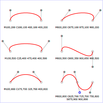
The following picture shows some how cubic Bézier
curves change their shape depending on the position of the
control points. The first five examples illustrate a single
cubic Bézier path segment. The example at the lower
right shows a "C" command followed by an "S" command.
View
this example as SVG (SVG-enabled browsers only)
8.3.7 The Quadratic Bézier curve commands
The 'Quadratic Bézier' commands are as follows:
| Command |
Name |
Parameters |
Description |
Q (absolute)
q (relative) |
quadratic Bézier curveto |
(x1 y1 x y)+ |
A quadratic Bézier curve is drawn from the current point to (x,y) using (x1,y1) as the control point. If multiple sets of coordinates are specified, a polybézier shall be drawn. At the end of the command, the new current point shall be the final (x,y) coordinate pair used in the polybézier. |
T (absolute)
t (relative) |
Shorthand/smooth quadratic Bézier curveto |
(x y)+ |
A quadratic Bézier curve is drawn from the current point to (x,y). The control point shall be the reflection of the control point on the previous command relative to the current point. (If there is no previous command or if the previous command was not a Q, q, T or t, the control point shall be current point.) If multiple sets of coordinates are specified, a polybézier shall be drawn. At the end of the command, the new current point shall be the final (x,y) coordinate pair used in the polybézier. |
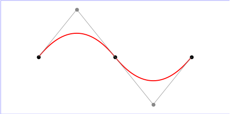
Example quad01 shows some
simple uses of 'Quadratic Bézier' commands within a path.
Note that the control point for the "T" command is computed
automatically as the reflection of the control point for the
previous "Q" command relative to the start point of the "T"
command.
<?xml version="1.0"?>
<!DOCTYPE svg PUBLIC "-//W3C//DTD SVG 1.1//EN"
  "http://www.w3.org/Graphics/SVG/1.1/DTD/svg11.dtd">
<svg width="12cm" height="6cm" viewBox="0 0 1200 600"
     xmlns="http://www.w3.org/2000/svg" version="1.2" baseProfile="tiny">
  <title>Example quad01 - quadratic Bezier commands in path data</title>
  <desc>Picture showing a "Q" a "T" command,
        along with annotations showing the control points
        and end points</desc>
  <rect x="1" y="1" width="1198" height="598"
        fill="none" stroke="blue" stroke-width="1" />
  <path d="M200,300 Q400,50 600,300 T1000,300"
        fill="none" stroke="red" stroke-width="5"  />
  <!-- End points -->
  <g fill="black" >
    <circle cx="200" cy="300" r="10"/>
    <circle cx="600" cy="300" r="10"/>
    <circle cx="1000" cy="300" r="10"/>
  </g>
  <!-- Control points and lines from end points to control points -->
  <g fill="#888888" >
    <circle cx="400" cy="50" r="10"/>
    <circle cx="800" cy="550" r="10"/>
  </g>
  <path d="M200,300 L400,50 L600,300
           L800,550 L1000,300"
        fill="none" stroke="#888888" stroke-width="2" />
</svg>
8.3.8 The grammar for path data
The following description of the grammar for path data uses Extended Backus-Naur Form [EBNF]:
path-data ::=
    wsp* moveto-drawto-command-groups? wsp*
moveto-drawto-command-groups ::=
    moveto-drawto-command-group
    | moveto-drawto-command-group wsp* moveto-drawto-command-groups
moveto-drawto-command-group ::=
    moveto wsp* drawto-commands?
drawto-commands ::=
    drawto-command
    | drawto-command wsp* drawto-commands
drawto-command ::=
    closepath
    | lineto
    | horizontal-lineto
    | vertical-lineto
    | curveto
    | smooth-curveto
    | quadratic-bezier-curveto
    | smooth-quadratic-bezier-curveto
moveto ::=
    ( "M" | "m" ) wsp* moveto-argument-sequence
moveto-argument-sequence ::=
    coordinate-pair
    | coordinate-pair comma-wsp? lineto-argument-sequence
closepath ::=
    ("Z" | "z")
lineto ::=
    ( "L" | "l" ) wsp* lineto-argument-sequence
lineto-argument-sequence ::=
    coordinate-pair
    | coordinate-pair comma-wsp? lineto-argument-sequence
horizontal-lineto ::=
    ( "H" | "h" ) wsp* horizontal-lineto-argument-sequence
horizontal-lineto-argument-sequence ::=
    coordinate
    | coordinate comma-wsp? horizontal-lineto-argument-sequence
vertical-lineto ::=
    ( "V" | "v" ) wsp* vertical-lineto-argument-sequence
vertical-lineto-argument-sequence ::=
    coordinate
    | coordinate comma-wsp? vertical-lineto-argument-sequence
curveto ::=
    ( "C" | "c" ) wsp* curveto-argument-sequence
curveto-argument-sequence ::=
    curveto-argument
    | curveto-argument comma-wsp? curveto-argument-sequence
curveto-argument ::=
    coordinate-pair comma-wsp? coordinate-pair comma-wsp? coordinate-pair
smooth-curveto ::=
    ( "S" | "s" ) wsp* smooth-curveto-argument-sequence
smooth-curveto-argument-sequence ::=
    smooth-curveto-argument
    | smooth-curveto-argument comma-wsp? smooth-curveto-argument-sequence
smooth-curveto-argument ::=
    coordinate-pair comma-wsp? coordinate-pair
quadratic-bezier-curveto ::=
    ( "Q" | "q" ) wsp* quadratic-bezier-curveto-argument-sequence
quadratic-bezier-curveto-argument-sequence ::=
    quadratic-bezier-curveto-argument
    | quadratic-bezier-curveto-argument comma-wsp?
        quadratic-bezier-curveto-argument-sequence
quadratic-bezier-curveto-argument ::=
    coordinate-pair comma-wsp? coordinate-pair
smooth-quadratic-bezier-curveto ::=
    ( "T" | "t" ) wsp* smooth-quadratic-bezier-curveto-argument-sequence
smooth-quadratic-bezier-curveto-argument-sequence ::=
    coordinate-pair
    | coordinate-pair comma-wsp? smooth-quadratic-bezier-curveto-argument-sequence
coordinate-pair ::=
    coordinate comma-wsp? coordinate
coordinate ::=
    number
nonnegative-number ::=
    integer-constant
    | floating-point-constant
number ::=
    sign? integer-constant
    | sign? floating-point-constant
flag ::=
    "0" | "1"
comma-wsp ::=
    (wsp+ comma? wsp*) | (comma wsp*)
comma ::=
    ","
integer-constant ::=
    digit-sequence
floating-point-constant ::=
    fractional-constant exponent?
    | digit-sequence exponent
fractional-constant ::=
    digit-sequence? "." digit-sequence
    | digit-sequence "."
exponent ::=
    ( "e" | "E" ) sign? digit-sequence
sign ::=
    "+" | "-"
digit-sequence ::=
    digit
    | digit digit-sequence
digit ::=
    "0" | "1" | "2" | "3" | "4" | "5" | "6" | "7" | "8" | "9"
wsp ::=
    (#x20 | #x9 | #xD | #xA)
The processing of the EBNF must consume as much of a given
EBNF production as possible, stopping at the point when a
character is encountered which no longer satisfies the
production. Thus, in the string 'M 100-200', the first
coordinate for the "moveto" consumes the characters "100" and
stops upon encountering the minus sign because the minus sign
cannot follow a digit in the production of a "coordinate". The
result is that the first coordinate will be "100" and the
second coordinate will be "-200".
Similarly, for the string 'M 0.6.5', the first coordinate of
the "moveto" consumes the characters "0.6" and stops upon
encountering the second decimal point because the production of
a "coordinate" only allows one decimal point. The result is
that the first coordinate will be "0.6" and the second
coordinate will be ".5".
Note that the EBNF allows the path 'd' attribute to be empty. This is not
an error, instead it disables rendering of the path. Values of
the 'd' that do not match the
EBNF are treated as unsupported.
8.4 Distance along a path
Various operations, including motion animation
and some stroke
operations, require that the user agent compute the
distance along the geometry of a graphics element, such as a
'path'.
To aid hand authoring by allowing convenient round numbers to be used, the 'pathLength' attribute can be used
to provide the author's computation of the total length of the
path so that the user agent can scale distance-along-a-path
computations by the ratio of 'pathLength' to the user agent's own
computed value for total path length.
A "moveto" operation within a 'path' element is defined to have
zero length. Only the various "lineto" and "curveto" commands
contribute to path length calculations.