Chapter 8: Paths
Contents
8.1. Introduction
A path represents the outline of a shape which can be filled or
stroked. A path can also be used as a clipping path, to describe
animation, or position text. A path can be used for more than one of
these functions at the same time. (See
Filling, Stroking and Paint Servers,
Clipping and Masking,
Animation ('animateMotion'),
and Text on a Path.)
A path is described using the concept of a current point. In
an analogy with drawing on paper, the current point can be
thought of as the location of the pen. The position of the pen
can be changed, and the outline of a shape (open or closed) can
be traced by dragging the pen in either straight lines or
curves.
Paths represent the geometry of the outline of an object,
defined in terms of moveto (set a new current point),
bearing (set a new orientation), lineto
(draw a straight line), curveto (draw
a curve using a cubic Bézier), arc (elliptical
or circular arc) and closepath (close the current
shape by connecting to the last moveto) commands.
Compound paths (i.e., a path with multiple subpaths) are
possible to allow effects such as "donut holes" in objects.
This chapter describes the syntax, behavior and DOM
interfaces for SVG paths. Various implementation notes for SVG
paths can be found in ‘path’ element implementation
Notes and Elliptical arc
implementation notes.
A path is defined in SVG using the ‘path’ element.
The basic shapes are all described in terms of what their
equivalent path is, which is
what their shape is as a path. (The equivalent path of a
‘path’ element is simply the path itself.)
8.2. The ‘path’ element
‘path’
- Categories:
- Graphics element, markable element, shape element
- Content model:
- Any number of the following elements, in any order:
- animation elements — ‘animate’, ‘animateMotion’, ‘animateTransform’, ‘discard’, ‘set’
- descriptive elements — ‘desc’, ‘title’, ‘metadata’
- paint server elements — ‘solidcolor’, ‘linearGradient’, ‘radialGradient’, ‘mesh’, ‘pattern’, ‘hatch’
clipPath, marker, mask, script - Attributes:
- aria attributes — ‘aria-activedescendant’, ‘aria-atomic’, ‘aria-autocomplete’, ‘aria-busy’, ‘aria-checked’, ‘aria-colcount’, ‘aria-colindex’, ‘aria-colspan’, ‘aria-controls’, ‘aria-current’, ‘aria-describedat’, ‘aria-describedby’, ‘aria-disabled’, ‘aria-dropeffect’, ‘aria-expanded’, ‘aria-flowto’, ‘aria-grabbed’, ‘aria-haspopup’, ‘aria-hidden’, ‘aria-invalid’, ‘aria-label’, ‘aria-labelledby’, ‘aria-level’, ‘aria-live’, ‘aria-modal’, ‘aria-multiline’, ‘aria-multiselectable’, ‘aria-orientation’, ‘aria-owns’, ‘aria-placeholder’, ‘aria-posinset’, ‘aria-pressed’, ‘aria-readonly’, ‘aria-relevant’, ‘aria-required’, ‘aria-rowcount’, ‘aria-rowindex’, ‘aria-rowspan’, ‘aria-selected’, ‘aria-setsize’, ‘aria-sort’, ‘aria-valuemax’, ‘aria-valuemin’, ‘aria-valuenow’, ‘aria-valuetext’, ‘role’
- conditional processing attributes — ‘requiredExtensions’, ‘systemLanguage’
- core attributes — ‘id’, ‘tabindex’, ‘lang’, ‘xml:space’
- global event attributes — ‘oncancel’, ‘oncanplay’, ‘oncanplaythrough’, ‘onchange’, ‘onclick’, ‘onclose’, ‘oncuechange’, ‘ondblclick’, ‘ondrag’, ‘ondragend’, ‘ondragenter’, ‘ondragexit’, ‘ondragleave’, ‘ondragover’, ‘ondragstart’, ‘ondrop’, ‘ondurationchange’, ‘onemptied’, ‘onended’, ‘onerror’, ‘onfocus’, ‘oninput’, ‘oninvalid’, ‘onkeydown’, ‘onkeypress’, ‘onkeyup’, ‘onload’, ‘onloadeddata’, ‘onloadedmetadata’, ‘onloadstart’, ‘onmousedown’, ‘onmouseenter’, ‘onmouseleave’, ‘onmousemove’, ‘onmouseout’, ‘onmouseover’, ‘onmouseup’, ‘onmousewheel’, ‘onpause’, ‘onplay’, ‘onplaying’, ‘onprogress’, ‘onratechange’, ‘onreset’, ‘onresize’, ‘onscroll’, ‘onseeked’, ‘onseeking’, ‘onselect’, ‘onshow’, ‘onstalled’, ‘onsubmit’, ‘onsuspend’, ‘ontimeupdate’, ‘ontoggle’, ‘onvolumechange’, ‘onwaiting’
- graphical event attributes — ‘onfocusin’, ‘onfocusout’
- presentation attributes —
- style attributes — ‘class’, ‘style’
- ‘d’
- ‘pathLength’
- DOM Interfaces:
-
-
The definition of the outline of a shape. See Path data.
Error processing for svg-path is done according to
Path Data Error Handling.
Path data animation is only possible when each path data
specification within an animation specification has exactly
the same list of path data commands as the ‘d’ attribute. If an animation is
specified and the list of path data commands is not the
same, then the animation specification is in error (see
Error Handling).
The animation engine interpolates each parameter to each
path data command separately based on the attributes to the
given animation element. Flags and booleans are
interpolated as fractions between zero and one, with any
non-zero value considered to be a value of one/true.
The initial value, (none) indicates
that the path element is valid but does not render.
-
| Name |
Value |
Initial value |
Animatable |
| pathLength |
<number> |
(none) |
yes |
-
The author's computation of the total length of the
path, in user units. This value is used to calibrate the
user agent's own distance-along-a-path
calculations with that of the author. The user agent will
scale all distance-along-a-path computations by the ratio
of ‘pathLength’ to the user
agent's own computed value for total path length. ‘pathLength’ potentially affects
calculations for text on a path,
motion animation and
various stroke operations.
A negative value is an error (see Error handling).
8.3. Path data
| SVG 2 Requirement: |
Support turtle-graphics-like current rotation in path syntax. |
| Resolution: |
We will add a path rotation command. |
| Purpose: |
Make path rotations easier to animate and pie charts easier to draw. |
| Owner: |
Cameron (ACTION-3125) |
A path is defined by including a ‘path’
element which contains a d="(path data)"
attribute, where the ‘d’ attribute contains the
moveto, bearing, lineto, curveto (both cubic and
quadratic Béziers), arc and closepath
instructions.
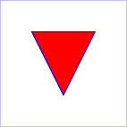
Example triangle01
specifies a path in the shape of a triangle. (The
M indicates a moveto, the
Ls indicate linetos, and the
z indicates a closepath).
<?xml version="1.0" standalone="no"?>
<svg width="4cm" height="4cm" viewBox="0 0 400 400"
     xmlns="http://www.w3.org/2000/svg" version="1.1">
  <title>Example triangle01- simple example of a 'path'</title>
  <desc>A path that draws a triangle</desc>
  <rect x="1" y="1" width="398" height="398"
        fill="none" stroke="blue" />
  <path d="M 100 100 L 300 100 L 200 300 z"
        fill="red" stroke="blue" stroke-width="3" />
</svg>View this example as SVG (SVG-enabled browsers only)
Path data can contain newline characters and thus can be
broken up into multiple lines to improve readability.
Newlines inside attributes in markup will be normalized to space
characters while parsing.
The syntax of path data is concise in order to allow for
minimal file size and efficient downloads, since many SVG files
will be dominated by their path data. Some of the ways that SVG
attempts to minimize the size of path data are as follows:
- All instructions are expressed as one character (e.g., a
moveto is expressed as an M).
- Superfluous white space and separators such as commas can
be eliminated (e.g., "M 100 100 L 200 200" contains
unnecessary spaces and could be expressed more compactly as
"M100 100L200 200").
- The command letter can be eliminated on subsequent
commands if the same command is used multiple times in a row
(e.g., you can drop the second "L" in "M 100 200 L 200 100 L
-100 -200" and use "M 100 200 L 200 100 -100 -200"
instead).
- For most commands there are absolute and relative
versions available (uppercase means absolute coordinates,
lowercase means relative coordinates).
- Alternate forms of lineto are available to
optimize the special cases of horizontal and vertical lines
(absolute and relative).
- Alternate forms of curve are available to
optimize the special cases where some of the control points
on the current segment can be determined automatically from
the control points on the previous segment.
The path data syntax is a prefix notation (i.e., commands
followed by parameters). The only allowable decimal point is a
Unicode
U+0046 FULL STOP (".") character (also referred to in Unicode as
PERIOD, dot and decimal point) and no other delimiter
characters are allowed [UNICODE].
(For example, the following is an
invalid numeric value in a path data stream: "13,000.56".
Instead, say: "13000.56".)
For the relative versions of the commands, all coordinate
values are relative to the current point at the start of the
command.
Relative path commands are also influenced by the
current bearing, which is an angle set by the bearing
commands. This allows for paths to be specified using a
style of "turtle graphics", where straight line and curved
path segments are placed with their starting point at a
tangent (or at some other angle) to the current bearing.
In the tables below, the following notation is used to
describe the syntax of a given path command:
- (): grouping of parameters
- +: 1 or more of the given parameter(s) is required
In the description of the path commands, cpx and
cpy represent the coordinates of the current point,
and cb represents the current bearing.
The following sections list the commands. Those that
draw straight line segments include the lineto commands
(L, l,
H, h, V and v)
and the close path commands
(Z and z). These three groups of commands draw curves:
- Cubic
Bézier commands (C,
c, S and
s). A cubic Bézier segment is defined
by a start point, an end point, and two control points.
- Quadratic
Bézier commands (Q,
q, T and
t). A quadratic Bézier segment is
defined by a start point, an end point, and one control
point.
- Elliptical
arc commands (A and a).
An elliptical arc segment draws a segment of an ellipse.
8.3.2. The "moveto" commands
The "moveto" commands (M or
m) establish a new current point. The effect
is as if the "pen" were lifted and moved to a new location. A
path data segment (if there is one) must begin with a "moveto"
command. Subsequent "moveto" commands (i.e., when the "moveto"
is not the first command) represent the start of a new
subpath:
| Command |
Name |
Parameters |
Description |
M (absolute)
m (relative) |
moveto |
(x y)+ |
Start a new sub-path at the given (x,y) coordinates.
M (uppercase) indicates that absolute
coordinates will follow; m (lowercase)
indicates that relative coordinates will follow. If a moveto is
followed by multiple pairs of coordinates, the subsequent pairs
are treated as implicit lineto commands. Hence, implicit lineto
commands will be relative if the moveto is relative, and
absolute if the moveto is absolute. If a relative moveto
(m) appears as the first element of the path,
then it is treated as a pair of absolute coordinates. In this
case, subsequent pairs of coordinates are treated as relative
even though the initial moveto is interpreted as an absolute moveto.
|
When a relative m command is used, the
position moved to is (cpx + x cos cb
+ y sin cb, cpy +
x sin cb + y cos cb).
8.3.3. The "closepath" command
The "closepath" (Z or z)
ends the current subpath by connecting it back to its initial point
in either of two ways:
-
If the previous command is
complete
, that is that all the
required coordinate data has been supplied, then an automatic
straight line is drawn from the current point to the initial
point of the current subpath. This path segment may be of zero
length.
-
If the previous command is missing required coordinate data then
the initial point is used to fill in the missing data (but only
for the last point or points).
Examples:
-
m 100,100 50,0 0,50 z:
Implicit l command complete, z causes a
straight line to be drawn resulting in a closed triangular path.
-
m 100,100 a 50,50 0 0 1 100,0 z:
a command complete, z causes a
straight line to be drawn resulting in a closed semi-circular path.
-
m 100,100 a 50,50 0 0 1 100,0 50,50 0 0 1 z:
Second set of coordinates for the a command
missing final point, z causes initial point to
be used as final point resulting in a closed circular path.
-
m 100,100 a 50,50 0 0 1 100,0 c z:
c command missing three coordinates,
z causes initial point to be used as coordinate
data for all c coordinates resulting in a
closed semi-circle. Visually c
z is the same as z but may be
useful in animating path data.
SVG 2 adds the ability to fill in missing coordinate data with
the Z or z command to avoid the
need to add a zero length (or very short in the case of relative
paths with rounding errors) path segment to close a subpath. This
can effect the number of markers drawn and their orientation at
the beginning/end of a closed subpath.
The use of Z or z to replace
missing coordinate data with the coordinate of the initial point in
a subpath was resolved at the
Sydney
(2015) meeting.
If a "closepath" is followed immediately by a
"moveto", then the "moveto" identifies the start point of the
next subpath. If a "closepath" is followed immediately by any
other command, then the next subpath starts at the same initial
point as the current subpath.
When a subpath ends in a "closepath," it differs in behavior
from what happens when "manually" closing a subpath via a
"lineto" command in how ‘stroke-linejoin’
and ‘stroke-linecap’ are implemented. With "closepath", the end of the final segment
of the subpath is "joined" with the start of the initial
segment of the subpath using the current value of ‘stroke-linejoin’.
If you instead "manually" close the subpath via a "lineto"
command, the start of the first segment and the end of the last
segment are not joined but instead are each capped using the
current value of ‘stroke-linecap’.
At the end of the command, the new current point is set to the
initial point of the current subpath.
The current bearing does not affect a z command.
| Command |
Name |
Parameters |
Description |
Z or
z |
closepath |
(none) |
Close the current subpath by connecting it back to the current
subpath's initial point (see prose above). Since the
Z and z
commands take no parameters, they have an identical effect. |
8.3.4. The "lineto" commands
The various "lineto" commands draw straight lines from the
current point to a new point:
| Command |
Name |
Parameters |
Description |
L (absolute)
l (relative) |
lineto |
(x y)+ |
Draw a line from the current point to the given (x,y)
coordinate which becomes the new current point.
L (uppercase) indicates that absolute
coordinates will follow; l (lowercase)
indicates that relative coordinates will follow. A number
of coordinates pairs may be specified to draw a polyline.
At the end of the command, the new current point is set to
the final set of coordinates provided. |
H (absolute)
h (relative) |
horizontal lineto |
x+ |
Draws a horizontal line from the current point.
H (uppercase) indicates
that absolute coordinates will follow; h
(lowercase) indicates that relative coordinates will
follow. Multiple x values can be provided (although usually
this doesn't make sense). An H or h
command is equivalent to an L or l
command with 0 specified for the y coordinate.
At the end of the command, the new current point is
taken from the final coordinate value. |
V (absolute)
v (relative) |
vertical lineto |
y+ |
Draws a vertical line from the current point.
V (uppercase) indicates that
absolute coordinates will follow; v
(lowercase) indicates that relative coordinates will
follow. Multiple y values can be provided (although usually
this doesn't make sense). A V or v
command is equivalent to an L or l
command with 0 specified for the x coordinate.
At the end of the command, the new current point is
taken from the final coordinate value. |
When a relative l command is used, the
end point of the line is (cpx + x cos cb
+ y sin cb, cpy +
x sin cb + y cos cb).
When a relative h command is used,
the end point of the line is (cpx + x cos cb,
cpy + x sin cb). This means
that an h command with a positive x
value draws a line in the direction of the current bearing. When
the current bearing is 0, this is a horizontal line in the direction
of the positive x-axis.
When there is a non-zero bearing, a mnemonic for the h
command could be "head this distance at the current bearing",
rather than "draw a horizontal line".
When a relative v command is used,
the end point of the line is (cpx + y sin cb,
cpy + y cos cb).
8.3.5. The cubic Bézier curve commands
The cubic Bézier commands are as follows:
| Command |
Name |
Parameters |
Description |
C (absolute)
c (relative) |
curveto |
(x1 y1 x2 y2 x y)+ |
Draws a cubic Bézier curve from the current
point to (x,y) using (x1,y1) as the control point at the
beginning of the curve and (x2,y2) as the control point at
the end of the curve. C (uppercase)
indicates that absolute coordinates will follow;
c (lowercase) indicates that relative
coordinates will follow. Multiple sets of coordinates may
be specified to draw a polybézier. At the end of the
command, the new current point becomes the final (x,y)
coordinate pair used in the polybézier. |
S (absolute)
s (relative) |
shorthand/smooth curveto |
(x2 y2 x y)+ |
Draws a cubic Bézier curve from the current
point to (x,y). The first control point is assumed to be
the reflection of the second control point on the previous
command relative to the current point. (If there is no
previous command or if the previous command was not an C,
c, S or s, assume the first control point is coincident
with the current point.) (x2,y2) is the second control
point (i.e., the control point at the end of the curve).
S (uppercase) indicates that absolute
coordinates will follow; s (lowercase)
indicates that relative coordinates will follow. Multiple
sets of coordinates may be specified to draw a
polybézier. At the end of the command, the new
current point becomes the final (x,y) coordinate pair used
in the polybézier. |
When a relative c or s
command is used, each of the relative coordinate pairs
is computed as for those in an m command.
For example, the final control point of the curve of
both commands is (cpx + x cos cb
+ y sin cb, cpy +
x sin cb + y cos cb).
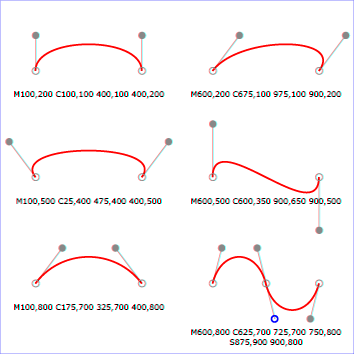
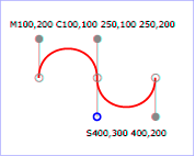
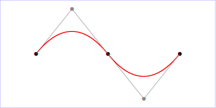
Example cubic01 shows some
simple uses of cubic Bézier commands within a path. The
example uses an internal CSS style sheet to assign styling
properties. Note that the control point for the "S" command is
computed automatically as the reflection of the control point
for the previous "C" command relative to the start point of the
"S" command.
<?xml version="1.0" standalone="no"?>
<svg width="5cm" height="4cm" viewBox="0 0 500 400"
     xmlns="http://www.w3.org/2000/svg" version="1.1">
  <title>Example cubic01- cubic Bézier commands in path data</title>
  <desc>Picture showing a simple example of path data
        using both a "C" and an "S" command,
        along with annotations showing the control points
        and end points</desc>
  <style type="text/css"><![CDATA[
    .Border { fill:none; stroke:blue; stroke-width:1 }
    .Connect { fill:none; stroke:#888888; stroke-width:2 }
    .SamplePath { fill:none; stroke:red; stroke-width:5 }
    .EndPoint { fill:none; stroke:#888888; stroke-width:2 }
    .CtlPoint { fill:#888888; stroke:none }
    .AutoCtlPoint { fill:none; stroke:blue; stroke-width:4 }
    .Label { font-size:22; font-family:Verdana }
  ]]></style>

  <rect class="Border" x="1" y="1" width="498" height="398" />

  <polyline class="Connect" points="100,200 100,100" />
  <polyline class="Connect" points="250,100 250,200" />
  <polyline class="Connect" points="250,200 250,300" />
  <polyline class="Connect" points="400,300 400,200" />
  <path class="SamplePath" d="M100,200 C100,100 250,100 250,200
                                       S400,300 400,200" />
  <circle class="EndPoint" cx="100" cy="200" r="10" />
  <circle class="EndPoint" cx="250" cy="200" r="10" />
  <circle class="EndPoint" cx="400" cy="200" r="10" />
  <circle class="CtlPoint" cx="100" cy="100" r="10" />
  <circle class="CtlPoint" cx="250" cy="100" r="10" />
  <circle class="CtlPoint" cx="400" cy="300" r="10" />
  <circle class="AutoCtlPoint" cx="250" cy="300" r="9" />
  <text class="Label" x="25" y="70">M100,200 C100,100 250,100 250,200</text>
  <text class="Label" x="325" y="350"
        style="text-anchor:middle">S400,300 400,200</text>
</svg>View this example as SVG (SVG-enabled browsers only)
The following picture shows some how cubic Bézier
curves change their shape depending on the position of the
control points. The first five examples illustrate a single
cubic Bézier path segment. The example at the lower
right shows a "C" command followed by an "S" command.
View
this example as SVG (SVG-enabled browsers only)
8.3.6. The quadratic Bézier curve commands
The quadratic Bézier commands are as follows:
| Command |
Name |
Parameters |
Description |
Q (absolute)
q (relative) |
quadratic Bézier curveto |
(x1 y1 x y)+ |
Draws a quadratic Bézier curve from the current
point to (x,y) using (x1,y1) as the control point.
Q (uppercase) indicates that absolute
coordinates will follow; q (lowercase)
indicates that relative coordinates will follow. Multiple
sets of coordinates may be specified to draw a
polybézier. At the end of the command, the new
current point becomes the final (x,y) coordinate pair used
in the polybézier. |
T (absolute)
t (relative) |
Shorthand/smooth quadratic Bézier curveto |
(x y)+ |
Draws a quadratic Bézier curve from the current
point to (x,y). The control point is assumed to be the
reflection of the control point on the previous command
relative to the current point. (If there is no previous
command or if the previous command was not a Q, q, T or t,
assume the control point is coincident with the current
point.) T (uppercase) indicates that
absolute coordinates will follow; t
(lowercase) indicates that relative coordinates will
follow. At the end of the command, the new current point
becomes the final (x,y) coordinate pair used in the
polybézier. |
When a relative q or t
command is used, each of the relative coordinate pairs
is computed as for those in an m command.
For example, the final control point of the curve of
both commands is (cpx + x cos cb
+ y sin cb, cpy +
x sin cb + y cos cb).
Example quad01 shows some
simple uses of quadratic Bézier commands within a path.
Note that the control point for the "T" command is computed
automatically as the reflection of the control point for the
previous "Q" command relative to the start point of the "T"
command.
<?xml version="1.0" standalone="no"?>
<svg width="12cm" height="6cm" viewBox="0 0 1200 600"
     xmlns="http://www.w3.org/2000/svg" version="1.1">
  <title>Example quad01 - quadratic Bézier commands in path data</title>
  <desc>Picture showing a "Q" a "T" command,
        along with annotations showing the control points
        and end points</desc>
  <rect x="1" y="1" width="1198" height="598"
        fill="none" stroke="blue" stroke-width="1" />

  <path d="M200,300 Q400,50 600,300 T1000,300"
        fill="none" stroke="red" stroke-width="5"  />
  <!-- End points -->
  <g fill="black" >
    <circle cx="200" cy="300" r="10"/>
    <circle cx="600" cy="300" r="10"/>
    <circle cx="1000" cy="300" r="10"/>
  </g>
  <!-- Control points and lines from end points to control points -->
  <g fill="#888888" >
    <circle cx="400" cy="50" r="10"/>
    <circle cx="800" cy="550" r="10"/>
  </g>
  <path d="M200,300 L400,50 L600,300
           L800,550 L1000,300"
        fill="none" stroke="#888888" stroke-width="2" />
</svg>View this example as SVG (SVG-enabled browsers only)
8.3.7. The elliptical arc curve commands
| SVG 2 Requirement: |
Make it simpler to draw arcs in SVG path syntax. |
| Resolution: |
Make arcs in paths easier. |
| Purpose: |
To make it easier for authors to write path data with arcs by hand. |
| Owner: |
Cameron (ACTION-3151) |
The elliptical arc commands are as follows:
| Command |
Name |
Parameters |
Description |
A (absolute)
a (relative) |
elliptical arc |
(rx ry x-axis-rotation large-arc-flag sweep-flag x
y)+ |
Draws an elliptical arc from the current point to
(x, y). The size and
orientation of the ellipse are defined by two radii
(rx, ry) and an
x-axis-rotation, which indicates how the
ellipse as a whole is rotated relative to the current
coordinate system. The center (cx,
cy) of the ellipse is calculated
automatically to satisfy the constraints imposed by the
other parameters. large-arc-flag and
sweep-flag contribute to the automatic
calculations and help determine how the arc is drawn. |
When a relative a command is used, the end point
of the arc is (cpx + x cos cb
+ y sin cb, cpy +
x sin cb + y cos cb).
The effective value of the x-axis-rotation parameter is
also affected by the current bearing: it is computed as
x-axis-rotation + cb.
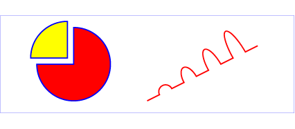
Example arcs01 shows some
simple uses of arc commands within a path.
<?xml version="1.0" standalone="no"?>
<svg width="12cm" height="5.25cm" viewBox="0 0 1200 400"
     xmlns="http://www.w3.org/2000/svg" version="1.1">
  <title>Example arcs01 - arc commands in path data</title>
  <desc>Picture of a pie chart with two pie wedges and
        a picture of a line with arc blips</desc>
  <rect x="1" y="1" width="1198" height="398"
        fill="none" stroke="blue" stroke-width="1" />

  <path d="M300,200 h-150 a150,150 0 1,0 150,-150 z"
        fill="red" stroke="blue" stroke-width="5" />
  <path d="M275,175 v-150 a150,150 0 0,0 -150,150 z"
        fill="yellow" stroke="blue" stroke-width="5" />

  <path d="M600,350 l 50,-25
           a25,25 -30 0,1 50,-25 l 50,-25
           a25,50 -30 0,1 50,-25 l 50,-25
           a25,75 -30 0,1 50,-25 l 50,-25
           a25,100 -30 0,1 50,-25 l 50,-25"
        fill="none" stroke="red" stroke-width="5"  />
</svg>View this example as SVG (SVG-enabled browsers only)
The elliptical arc command draws a section of an ellipse
which meets the following constraints:
- the arc starts at the current point
- the arc ends at point (x,
y)
- the ellipse has the two radii (rx,
ry)
- the x-axis of the ellipse is rotated by
x-axis-rotation relative to the x-axis of
the current coordinate system.
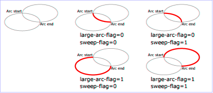
For most situations, there are actually four different arcs
(two different ellipses, each with two different arc sweeps)
that satisfy these constraints. large-arc-flag
and sweep-flag indicate which one of the four
arcs are drawn, as follows:
- Of the four candidate arc sweeps, two will represent an
arc sweep of greater than or equal to 180 degrees (the
"large-arc"), and two will represent an arc sweep of less
than or equal to 180 degrees (the "small-arc"). If
large-arc-flag is '1', then one of the two
larger arc sweeps will be chosen; otherwise, if
large-arc-flag is '0', one of the smaller
arc sweeps will be chosen,
- If sweep-flag is '1', then the arc will
be drawn in a "positive-angle" direction (i.e., the ellipse
formula x=cx+rx*cos(theta)
and y=cy+ry*sin(theta) is
evaluated such that theta starts at an angle corresponding to
the current point and increases positively until the arc
reaches (x,y)). A value of 0 causes the arc to be drawn in a
"negative-angle" direction (i.e., theta starts at an angle
value corresponding to the current point and decreases until
the arc reaches (x,y)).
The following illustrates the four combinations of
large-arc-flag and sweep-flag
and the four different arcs that will be drawn based on the
values of these flags. For each case, the following path data
command was used:
<path d="M 125,75 a100,50 0 ?,? 100,50"
      style="fill:none; stroke:red; stroke-width:6"/>
where "?,?" is replaced by "0,0" "0,1" "1,0" and "1,1" to
generate the four possible cases.
View
this example as SVG (SVG-enabled browsers only)
Refer to Elliptical arc
implementation notes for detailed implementation notes for
the path data elliptical arc commands.
8.3.8. The grammar for path data
Update for new 'Z'/'z' behavior.
SVG path data matches the following EBNF grammar.
svg-path:
    wsp* moveto-drawto-command-groups? wsp*
moveto-drawto-command-groups:
    moveto-drawto-command-group
    | moveto-drawto-command-group wsp* moveto-drawto-command-groups
moveto-drawto-command-group:
    moveto wsp* drawto-commands?
drawto-commands:
    drawto-command
    | drawto-command wsp* drawto-commands
drawto-command:
    closepath
    | lineto
    | horizontal-lineto
    | vertical-lineto
    | curveto
    | smooth-curveto
    | quadratic-bezier-curveto
    | smooth-quadratic-bezier-curveto
    | elliptical-arc
    | bearing
moveto:
    ( "M" | "m" ) wsp* moveto-argument-sequence
moveto-argument-sequence:
    coordinate-pair
    | coordinate-pair comma-wsp? lineto-argument-sequence
closepath:
    ("Z" | "z")
lineto:
    ( "L" | "l" ) wsp* lineto-argument-sequence
lineto-argument-sequence:
    coordinate-pair
    | coordinate-pair comma-wsp? lineto-argument-sequence
horizontal-lineto:
    ( "H" | "h" ) wsp* horizontal-lineto-argument-sequence
horizontal-lineto-argument-sequence:
    coordinate
    | coordinate comma-wsp? horizontal-lineto-argument-sequence
vertical-lineto:
    ( "V" | "v" ) wsp* vertical-lineto-argument-sequence
vertical-lineto-argument-sequence:
    coordinate
    | coordinate comma-wsp? vertical-lineto-argument-sequence
curveto:
    ( "C" | "c" ) wsp* curveto-argument-sequence
curveto-argument-sequence:
    curveto-argument
    | curveto-argument comma-wsp? curveto-argument-sequence
curveto-argument:
    coordinate-pair comma-wsp? coordinate-pair comma-wsp? coordinate-pair
smooth-curveto:
    ( "S" | "s" ) wsp* smooth-curveto-argument-sequence
smooth-curveto-argument-sequence:
    smooth-curveto-argument
    | smooth-curveto-argument comma-wsp? smooth-curveto-argument-sequence
smooth-curveto-argument:
    coordinate-pair comma-wsp? coordinate-pair
quadratic-bezier-curveto:
    ( "Q" | "q" ) wsp* quadratic-bezier-curveto-argument-sequence
quadratic-bezier-curveto-argument-sequence:
    quadratic-bezier-curveto-argument
    | quadratic-bezier-curveto-argument comma-wsp?
        quadratic-bezier-curveto-argument-sequence
quadratic-bezier-curveto-argument:
    coordinate-pair comma-wsp? coordinate-pair
smooth-quadratic-bezier-curveto:
    ( "T" | "t" ) wsp* smooth-quadratic-bezier-curveto-argument-sequence
smooth-quadratic-bezier-curveto-argument-sequence:
    coordinate-pair
    | coordinate-pair comma-wsp? smooth-quadratic-bezier-curveto-argument-sequence
elliptical-arc:
    ( "A" | "a" ) wsp* elliptical-arc-argument-sequence
elliptical-arc-argument-sequence:
    elliptical-arc-argument
    | elliptical-arc-argument comma-wsp? elliptical-arc-argument-sequence
elliptical-arc-argument:
    number comma-wsp? number comma-wsp?
        number comma-wsp flag comma-wsp? flag comma-wsp? coordinate-pair
bearing:
    ( "B" | "b" ) wsp* bearing-argument-sequence
bearing-argument-sequence:
    number
    | number comma-wsp? bearing-argument-sequence
coordinate-pair:
    coordinate comma-wsp? coordinate
coordinate:
    number
nonnegative-number:
    integer-constant
    | floating-point-constant
number:
    sign? integer-constant
    | sign? floating-point-constant
flag:
    "0" | "1"
integer-constant:
    digit-sequence
floating-point-constant:
    fractional-constant exponent?
    | digit-sequence exponent
fractional-constant:
    digit-sequence? "." digit-sequence
    | digit-sequence "."
exponent:
    ( "e" | "E" ) sign? digit-sequence
sign:
    "+" | "-"
digit-sequence:
    digit
    | digit digit-sequence
digit:
    "0" | "1" | "2" | "3" | "4" | "5" | "6" | "7" | "8" | "9"
The processing of the BNF must consume as much of a given
BNF production as possible, stopping at the point when a
character is encountered which no longer satisfies the
production. Thus, in the string "M 100-200", the first
coordinate for the "moveto" consumes the characters "100" and
stops upon encountering the minus sign because the minus sign
cannot follow a digit in the production of a "coordinate". The
result is that the first coordinate will be "100" and the
second coordinate will be "-200".
Similarly, for the string "M 0.6.5", the first coordinate of
the "moveto" consumes the characters "0.6" and stops upon
encountering the second decimal point because the production of
a "coordinate" only allows one decimal point. The result is
that the first coordinate will be "0.6" and the second
coordinate will be ".5".
Note that the BNF allows the path ‘d’ attribute to be empty. This is not
an error, instead it disables rendering of the path.
If path data not matching the grammar is encountered, then the path data is in error
(see Error Handling).
8.4. Implementation notes
8.4.1. Error handling in path data
A conforming SVG user agent must implement path rendering as follows:
8.5. Distance along a path
Various operations, including text on a path and motion animation
and various stroke
operations, require that the user agent compute the
distance along the geometry of a graphics element, such as a ‘path’.
Exact mathematics exist for computing distance along a path,
but the formulas are highly complex and require substantial
computation. It is recommended that authoring products and user
agents employ algorithms that produce as precise results as
possible; however, to accommodate implementation differences
and to help distance calculations produce results that
approximate author intent, the ‘pathLength’ attribute can be used
to provide the author's computation of the total length of the
path so that the user agent can scale distance-along-a-path
computations by the ratio of ‘pathLength’ to the user agent's own
computed value for total path length.
A "moveto" or "bearing" operation within a ‘path’ element is defined to have
zero length. Only the various "lineto", "curveto" and "arcto"
commands contribute to path length calculations.
8.6. DOM interfaces
8.6.1. Interface SVGPathElement
An SVGPathElement object represents a ‘path’ in the DOM.
interface SVGPathElement : SVGGeometryElement {

  [SameObject] readonly attribute SVGAnimatedNumber pathLength;

  float getTotalLength();
  DOMPoint getPointAtLength(float distance);
};
The pathLength IDL attribute
reflects the ‘pathLength’ content attribute.
The getTotalLength method
is used to compute the length of the path. When getTotalLength()
is called, the user agent's computed value for the total length of the path,
in user units, is returned.
The user agent's computed path length does not take the
‘pathLength’ attribute into account.
The getPointAtLength method
is used to return the point at a given distance along the path. When
getPointAtLength(distance) is called, the following steps are run:
- Let length be the user agent's computed value for the total
length of the path, in user units.
As with getTotalLength,
this does not take into account the ‘pathLength’ attribute.
- Clamp distance to [0, length].
- Let (x, y) be the point on the path at distance
distance.
- Return a newly created, detached
DOMPoint object representing the point
(x, y).