This specification defines the 2D Context for the HTML
canvas element. The 2D Context provides
objects, methods, and properties to draw and manipulate
graphics on a canvas drawing surface.
Status of This Document
This section describes the status of this document at the time of its publication. Other documents may supersede this document. A list of current W3C publications and the latest revision of this technical report can be found in the W3C technical reports index at http://www.w3.org/TR/.
This is the specification for the 2D Context for the HTML canvas element, published by the HTML Working Group.
If you wish to make comments regarding this document in a manner
that is tracked by the W3C, please submit them via using our
public issues list. If you cannot do this then you can also e-mail feedback to public-canvas-api@w3.org
(subscribe,
archives),
and arrangements will be made to transpose the comments to our
public bug database. All feedback is welcome.
By publishing this Recommendation, W3C expects the functionality specified in this Recommendation will not be affected by changes to Web IDL, CSS Object Model, CSS Images Values, or CSS Fonts as those specifications proceed to Recommendation.
Work on extending this specification typically proceeds through
extension specifications
which should be consulted to see what new features are being reviewed.
The bulk of the text of this specification is also
available in the WHATWG HTML Living Standard, under a license that permits reuse of the specification text.
Work on this specification is also done at the WHATWG. The W3C HTML working group actively pursues convergence of the
HTML specification with the WHATWG living standard, within the bounds of the W3C HTML working
group charter. There are various ways to follow this work at the WHATWG:
This document has been reviewed by W3C Members, by software developers, and by other W3C groups and interested parties, and is endorsed by the Director as a W3C Recommendation. It is a stable document and may be used as reference material or cited from another document. W3C's role in making the Recommendation is to draw attention to the specification and to promote its widespread deployment. This enhances the functionality and interoperability of the Web.
The old issue list is still available. No changes were done since the previous publication.
This specification is an extension to the HTML5 language. All
normative content in the HTML5 specification, unless specifically
overridden by this specification, is intended to be the basis for
this specification.
This specification is an HTML specification. All the conformance
requirements, conformance classes, definitions, dependencies,
terminology, and typographical conventions described in the core
HTML5 specification apply to this specification. [HTML]
Interfaces are defined in terms of Web IDL. [WEBIDL]
This specification defines the 2d context type, whose
API is implemented using the CanvasRenderingContext2D
interface.
When the getContext()
method of a canvas element is to return a new object for the contextId2d, the user agent must return a
new CanvasRenderingContext2D object. Any additional
arguments are ignored.
The 2D context represents a flat Cartesian surface whose origin
(0,0) is at the top left corner, with the coordinate space having
x values increasing when going right, and y values increasing when going down.
The canvas
attribute must return the canvas element that the
context paints on.
Except where otherwise specified, for the 2D context interface,
any method call with a numeric argument whose value is
infinite or a NaN value must be ignored.
Whenever the CSS value currentColor is used
as a color in this API, the "computed value of the 'color' property"
for the purposes of determining the computed value of the currentColor keyword is the computed value of the
'color' property on the element in question at the time that the
color is specified (e.g. when the appropriate attribute is set, or
when the method is called; not when the color is rendered or
otherwise used). If the computed value of the 'color' property is
undefined for a particular case (e.g. because the element is not
in a Document), then the "computed value
of the 'color' property" for the purposes of determining the
computed value of the currentColor keyword is
fully opaque black. [CSSCOLOR]
In the case of addColorStop() on
CanvasGradient, the "computed value of the 'color'
property" for the purposes of determining the computed value of the
currentColor keyword is always fully opaque
black (there is no associated element). [CSSCOLOR]
This is because CanvasGradient objects
are canvas-neutral — a
CanvasGradient object created by one
canvas can be used by another, and there is therefore
no way to know which is the "element in question" at the time that
the color is specified.
Similar concerns exist with font-related properties;
the rules for those are described in detail in the relevant section
below.
2 The canvas state
Each context maintains a stack of drawing states. Drawing states consist of:
The current path and the
current bitmap are not part of the drawing state. The current
path is persistent, and can only be reset using the
beginPath() method.
The current bitmap is a property of the canvas, not the context.
Pops the top state on the stack, restoring the context to that state.
The save()
method must push a copy of the current drawing state onto the
drawing state stack.
The restore() method
must pop the top entry in the drawing state stack, and reset the
drawing state it describes. If there is no saved state, the method
must do nothing.
Sets the current line dash pattern (as used when stroking). The
argument is an array of distances for which to alternately have
the line on and the line off.
Returns the phase offset (in the same units as the line dash pattern).
Can be set, to change the phase offset. Values that are not
finite values are ignored.
Objects that implement the CanvasDrawingStyles
interface have attributes and methods (defined in this section) that
control how lines are treated by the object.
The lineWidth
attribute gives the width of lines, in coordinate space units. On
getting, it must return the current value. On setting, zero,
negative, infinite, and NaN values must be ignored, leaving the
value unchanged; other values must change the current value to the
new value.
When the object implementing the CanvasDrawingStyles
interface is created, the lineWidth attribute must
initially have the value 1.0.
The lineCap attribute
defines the type of endings that UAs will place on the end of lines.
The three valid values are "butt", "round",
and "square".
On getting, it must return the current value. On setting, if the
new value is one of the literal strings "butt",
"round", and "square", then the current value
must be changed to the new value; other values must be ignored, leaving
the value unchanged.
When the object implementing the CanvasDrawingStyles
interface is created, the lineCap attribute must
initially have the value "butt".
The lineJoin
attribute defines the type of corners that UAs will place where two
lines meet. The three valid values are "bevel",
"round", and "miter".
On getting, it must return the current value. On setting, if the
new value is one of the literal strings "bevel",
"round", and "miter", then the current value
must be changed to the new value; other values must be ignored,
leaving the value unchanged.
When the object implementing the CanvasDrawingStyles
interface is created, the lineJoin attribute must
initially have the value "miter".
When the lineJoin
attribute has the value "miter", strokes use the miter
limit ratio to decide how to render joins. The miter limit ratio can
be explicitly set using the miterLimit
attribute. On getting, it must return the current value. On setting,
zero, negative, infinite, and NaN values must be ignored, leaving
the value unchanged; other values must change the current value to
the new value.
When the object implementing the CanvasDrawingStyles
interface is created, the miterLimit attribute must
initially have the value 10.0.
Each CanvasDrawingStyles object has a dash
list, which is either empty or consists of an even number of
positive non-zero numbers. Initially, the dash list
must be empty.
When the setLineDash()
method is invoked, it must run the following steps:
Let a be a copy of the array provided as
the argument.
If any value in the array is not finite (e.g. an Infinity or
a NaN value), or if any value is negative (less than zero), then
abort these steps (without throwing an exception; user agents could
show a message on a developer console, though, as that would be
helpful for debugging).
If the number of elements in a is odd,
then let a be the concatenation of two copies
of a.
When the getLineDash()
method is invoked, it must return a newly created array whose values
are the values of the object's dash list, in the same
order.
It is sometimes useful to change the "phase" of the dash pattern,
e.g. to achieve a "marching ants" effect. The phase can be set using
the lineDashOffset
attribute. On getting, it must return the current value. On setting,
infinite and NaN values must be ignored, leaving the value
unchanged; other values must change the current value to the new
value.
When the object implementing the CanvasDrawingStyles
interface is created, the lineDashOffset
attribute must initially have the value 0.0.
When a user agent is to trace a path,
given an object style that implements the CanvasDrawingStyles
interface, it must run the following algorithm. This algorithm returns a new path.
Let path be a copy of the path being traced.
Prune all zero-length line segments from path.
Remove from path any subpaths containing no lines (i.e. subpaths with
just one point).
Replace each point in each subpath of path other than the first point
and the last point of each subpath by a join that joins the line leading to that point to
the line leading out of that point, such that the subpaths all consist of two points (a starting
point with a line leading out of it, and an ending point with a line leading into it), one or
more lines (connecting the points and the joins), and zero or more joins (each connecting one
line to another), connected together such that each subpath is a series of one or more lines with
a join between each one and a point on each end.
Add a straight closing line to each closed subpath in path connecting
the last point and the first point of that subpath; change the last point to a join (from the
previously last line to the newly added closing line), and change the first point to a join (from
the newly added closing line to the first line).
If the stylesdash list is empty, jump to the step
labeled convert.
Let pattern width be the concatenation of all the entries of the stylesdash list, in coordinate space units.
For each subpath subpath in path, run the
following substeps. These substeps mutate the subpaths in pathin
vivo.
Let subpath width be the length of all the lines of subpath, in coordinate space units.
Let offset be the value of the styleslineDashOffset, in coordinate space
units.
While offset is greater than pattern width,
decrement it by pattern width.
While offset is less than zero, increment it by pattern
width.
Define L to be a linear coordinate line defined along all lines in
subpath, such that the start of the first line in the subpath is defined
as coordinate 0, and the end of the last line in the subpath is defined as coordinate subpath width.
Let position be zero minus offset.
Let index be 0.
Let current state be off (the other states being on
and zero-on).
Dash on: Let segment length be
the value of the stylesdash
list's indexth entry.
Increment position by segment length.
If position is greater than subpath width, then
end these substeps for this subpath and start them again for the next subpath; if there are no
more subpaths, then jump to the step labeled convert instead.
If segment length is non-zero, let current state be on.
Increment index by one.
Dash off: Let segment
length be the value of the stylesdash list's indexth entry.
Let start be the offset position on L.
Increment position by segment length.
If position is less than zero, then jump to the step labeled
post-cut.
If start is less than zero, then let start be
zero.
If position is greater than subpath width, then
let end be the offset subpath width on L. Otherwise, let end be the offset position on L.
Run one of the following substeps, as appropriate:
If segment length is zero and current state is off
Do nothing, just continue to the next step.
If current state is off
Cut the line on which end finds itself short at end and place a point there, cutting its containing subpath in two;
remove all line segments, joins, points, and subpaths that are between start and end; and finally place a single point at start with no lines connecting to it.
The point has a directionality for the purposes of drawing line caps (see below).
The directionality is the direction that the original line had at that point (i.e. when L was defined above).
Otherwise
Cut the line on which start finds itself into two at start and place a point there, cutting the subpath that it was in in two, and
similarly cut the line on which end finds itself short at end and place a point there, cutting the subpath that it was in in
two, and then remove all line segments, joins, points, and subpaths that are between start and end.
If start and end are the same point, then this
results in just the line being cut in two and two points being inserted there, with nothing
being removed, unless a join also happens to be at that point, in which case the join must
be removed.
Post-cut: If position is greater than subpath width, then jump to the step labeled convert.
If segment length is greater than zero, let positioned-at-on-dash be false.
Increment index by one. If it is equal to the number of entries in
the stylesdash list, then let index be
0.
Convert: This is the step that converts the path to a new path that represents its
stroke.
Create a new path that describes the edge of the areas that
would be covered if a straight line of length equal to the styleslineWidth was swept along each path in path while being kept at an angle such that the line is orthogonal to the path
being swept, replacing each point with the end cap necessary to satisfy the styleslineCap attribute as described
previously and elaborated below, and replacing each join with the join necessary to satisfy the
styleslineJoin type, as
defined below.
Caps: Each point has a flat edge perpendicular to the direction of the line
coming out of it. This is them augmented according to the value of the styleslineCap. The "butt"
value means that no additional line cap is added. The "round" value means that a
semi-circle with the diameter equal to the styleslineWidth width must additionally be placed onto the
line coming out of each point. The "square" value means that a rectangle with the
length of the styleslineWidth
width and the width of half the styleslineWidth width, placed flat against the edge
perpendicular to the direction of the line coming out of the point, must be added at each
point.
Points with no lines coming out of them must have two caps placed back-to-back as if it was
really two points connected to each other by an infinitesimally short straight line in the
direction of the point's directionality (as defined above).
Joins: In addition to the point where a join occurs, two additional points
are relevant to each join, one for each line: the two corners found half the line width away
from the join point, one perpendicular to each line, each on the side furthest from the other
line.
A filled triangle connecting these two opposite corners with a straight line, with the third
point of the triangle being the join point, must be added at all joins. The lineJoin attribute controls whether anything else is
rendered. The three aforementioned values have the following meanings:
The "bevel" value means that this is all that is rendered at joins.
The "round" value means that a filled arc connecting the two aforementioned
corners of the join, abutting (and not overlapping) the aforementioned triangle, with the
diameter equal to the line width and the origin at the point of the join, must be added at
joins.
The "miter" value means that a second filled triangle must (if it can given the
miter length) be added at the join, with one line being the line between the two aforementioned
corners, abutting the first triangle, and the other two being continuations of the outside edges
of the two joining lines, as long as required to intersect without going over the miter
length.
The miter length is the distance from the point where the join occurs to the intersection of
the line edges on the outside of the join. The miter limit ratio is the maximum allowed ratio of
the miter length to half the line width. If the miter length would cause the miter limit ratio
(as set by the stylemiterLimit attribute) to be exceeded, this second
triangle must not be added.
Subpaths in the newly created path must wind clockwise, regardless of the direction of paths
in path.
Can be set, to change the alignment. The possible values are
"start", "end", "left", "right", and "center". Other values are ignored. The default is
"start".
Can be set, to change the baseline alignment. The possible
values and their meanings are given below. Other values are
ignored. The default is "alphabetic".
The font IDL
attribute, on setting, must be parsed the same way as the 'font'
property of CSS (but without supporting property-independent style
sheet syntax like 'inherit'), and the resulting font must be
assigned to the context, with the 'line-height' component forced to
'normal', with the 'font-size' component converted to CSS pixels,
and with system fonts being computed to explicit values. If the new
value is syntactically incorrect (including using
property-independent style sheet syntax like 'inherit' or
'initial'), then it must be ignored, without assigning a new font
value. [CSS]
Font names must be interpreted in the context of the font
style source node's stylesheets when the font is to be used;
any fonts embedded using @font-face that are
visible to that element must therefore be available once they are
loaded. (If a reference font is used before it is fully loaded, or
if the font style source node does not have that font
in scope at the time the font is to be used, then it must be treated
as if it was an unknown font, falling back to another as described
by the relevant CSS specifications.) [CSSFONTS]
Only vector fonts should be used by the user agent; if a user
agent were to use bitmap fonts then transformations would likely
make the font look very ugly.
On getting, the font
attribute must return the serialized form of the current font of the context
(with no 'line-height' component). [CSSOM]
...the expression context.font would
evaluate to the string "italic 12px "Unknown Font", sans-serif". The
"400" font-weight doesn't appear because that is the default
value. The line-height doesn't appear because it is forced to
"normal", the default value.
When the context is created, the font of the context must be set to 10px
sans-serif. When the 'font-size' component is set to lengths using
percentages, 'em' or 'ex' units, or the 'larger' or 'smaller'
keywords, these must be interpreted relative to the computed value
of the 'font-size' property of the font style source
node at the time that the attribute is set, if that is an
element. When the 'font-weight' component is set to the relative
values 'bolder' and 'lighter', these must be interpreted relative to
the computed value of the 'font-weight' property of the font
style source node at the time that the attribute is set, if
that is an element. If the computed values are undefined for a
particular case (e.g. because the font style source
node is not an element or is not in a
Document), then the relative keywords must be
interpreted relative to the normal-weight 10px sans-serif
default.
The textAlign IDL
attribute, on getting, must return the current value. On setting, if
the value is one of "start", "end", "left", "right", or "center", then the
value must be changed to the new value. Otherwise, the new value
must be ignored. When the context is created, the textAlign attribute must
initially have the value "start".
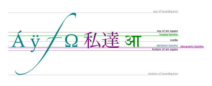
The textBaseline
IDL attribute, on getting, must return the current value. On
setting, if the value is one of "top", "hanging", "middle", "alphabetic",
"ideographic",
or "bottom",
then the value must be changed to the new value. Otherwise, the new
value must be ignored. When the object implementing the
CanvasDrawingStyles interface is created, the textBaseline attribute
must initially have the value "alphabetic".
The textBaseline
attribute's allowed keywords correspond to alignment points in the
font:
The keywords map to these alignment points as follows:
top
The top of the em square
hanging
The hanging baseline
middle
The middle of the em square
alphabetic
The alphabetic baseline
ideographic
The ideographic baseline
bottom
The bottom of the em square
The text preparation algorithm is as follows. It takes
as input a string text, a
CanvasDrawingStyles object target,
and an optional length maxWidth. It returns an
array of glyph shapes, each positioned on a common coordinate space,
and a physical alignment whose value is one of
left, right, and center. (Most callers of this
algorithm ignore the physical alignment.)
If maxWidth was provided but is less
than or equal to zero, return an empty array.
Replace all the space
characters in text with U+0020 SPACE
characters.
Let font be the current font of target, as given by that object's font attribute.
Apply the appropriate step from the following list to determine
the value of direction:
If the target object's font style
source node is an element
Let direction be the
directionality of the target object's
font style source node.
If the target object's font style
source node is a Document and that
Document has a root element child
Let direction be the
directionality of the target object's
font style source node's root element child.
If the target object's font style
source node is a Document and that
Document has no root element child
Let direction be 'ltr'.
Form a hypothetical infinitely-wide CSS line box containing
a single inline box containing the text text,
with all the properties at their initial values except the 'font'
property of the inline box set to font, the
'direction' property of the inline box set to direction, and the 'white-space' property set to
'pre'. [CSS]
If maxWidth was provided and the
hypothetical width of the inline box in the hypothetical line box
is greater than maxWidth CSS pixels, then
change font to have a more condensed font (if
one is available or if a reasonably readable one can be synthesized
by applying a horizontal scale factor to the font) or a smaller
font, and return to the previous step.
The anchor point is a point on the inline
box, and the physical alignment is one of the
values left, right, and center. These
variables are determined by the textAlign and textBaseline values as
follows:
Let the anchor point's vertical position
be the bottom of the em box of the first available font of the
inline box.
Let result be an array constructed by
iterating over each glyph in the inline box from left to right (if
any), adding to the array, for each glyph, the shape of the glyph
as it is in the inline box, positioned on a coordinate space using
CSS pixels with its origin is at the anchor
point.
Return result, and, for callers that
need it, physical alignment as the alignment
value.
5 Building paths
Each object implementing the CanvasPathMethods
interface has a path. A path has a list of zero or more subpaths.
Each subpath consists of a list of one or more points, connected by
straight or curved lines, and a flag indicating whether the subpath
is closed or not. A closed subpath is one where the last point of
the subpath is connected to the first point of the subpath by a
straight line. Subpaths with fewer than two points are ignored when
painting the path.
When an object implementing the CanvasPathMethods
interface is created, its path
must be initialized to zero subpaths.
Adds points to the subpath such that the arc described by the
circumference of the circle described by the arguments, starting
at the given start angle and ending at the given end angle, going
in the given direction (defaulting to clockwise), is added to the
path, connected to the previous point by a straight line.
Throws an IndexSizeError exception if the given
radius is negative.
The moveTo(x, y) method must
create a new subpath with the specified point as its first (and
only) point.
When the user agent is to ensure there is a subpath
for a coordinate (x, y) on a
path, the user agent must check to
see if the path has any subpaths,
and if it does not, then the user agent must create a new subpath
with the point (x, y) as its
first (and only) point, as if the moveTo() method had been
called.
The closePath()
method must do nothing if the object's path has no subpaths.
Otherwise, it must mark the last subpath as closed, create a new
subpath whose first point is the same as the previous subpath's
first point, and finally add this new subpath to the path.
If the last subpath had more than one point in its
list of points, then this is equivalent to adding a straight line
connecting the last point back to the first point, thus "closing"
the shape, and then repeating the last (possibly implied) moveTo() call.
New points and the lines connecting them are added to subpaths
using the methods described below. In all cases, the methods only
modify the last subpath in the object's path.
The lineTo(x, y) method must
ensure there is a subpath for (x, y) if the object's path
has no subpaths. Otherwise, it must connect the last point in the
subpath to the given point (x, y) using a straight line, and must then add the given
point (x, y) to the
subpath.
The quadraticCurveTo(cpx, cpy, x,
y) method must ensure there
is a subpath for (cpx,
cpy), and then must connect the last
point in the subpath to the given point (x, y) using a quadratic Bézier curve with control
point (cpx, cpy), and must
then add the given point (x, y) to the subpath. [BEZIER]
The bezierCurveTo(cp1x, cp1y, cp2x, cp2y, x, y) method must
ensure there is a subpath for (cp1x, cp1y), and then must
connect the last point in the subpath to the given point (x, y) using a cubic Bézier
curve with control points (cp1x, cp1y) and (cp2x, cp2y). Then, it must add the point (x, y) to the subpath. [BEZIER]
The arcTo(x1, y1, x2,
y2, radius)
method must first ensure there is a subpath for (x1, y1).
Then, the behavior depends on the arguments and the last point in
the subpath, as described below.
Negative values for radius must cause the
implementation to throw an IndexSizeError exception.
Let the point (x0, y0) be
the last point in the subpath.
If the point (x0, y0) is
equal to the point (x1, y1),
or if the point (x1, y1) is
equal to the point (x2, y2),
or if the radius radius is zero, then the method
must add the point (x1, y1)
to the subpath, and connect that point to the previous point (x0, y0) by a straight line.
Otherwise, if the points (x0, y0), (x1, y1), and (x2, y2) all lie on a single straight line, then the
method must add the point (x1, y1) to the subpath, and connect that point to the
previous point (x0, y0) by a
straight line.
Otherwise, let The Arc be the shortest arc
given by circumference of the circle that has radius radius, and that has one point tangent to the half-infinite
line that crosses the point (x0, y0) and ends at the point (x1,
y1), and that has a different point tangent to
the half-infinite line that ends at the point (x1, y1), and crosses the point
(x2, y2). The points at
which this circle touches these two lines are called the start and
end tangent points respectively. The method must connect the point
(x0, y0) to the start
tangent point by a straight line, adding the start tangent point to
the subpath, and then must connect the start tangent point to the
end tangent point by The Arc, adding the end
tangent point to the subpath.
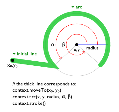
The arc(x, y, radius,
startAngle, endAngle, counterclockwise) method draws an arc.
If the context has any subpaths, then the method must add a straight
line from the last point in the subpath to the start point of the arc.
In any case, it must draw the arc between the start point of the arc and
the end point of the arc, and add the start and end points of the arc to
the subpath. The arc and its start and end points are defined as follows:
Consider a circle that has its origin at (x, y),
and that has radius radius.
The points at startAngle and endAngle this circle's circumference, measured
in radians clockwise from the positive x-axis, are the start and end points respectively.
If the counterclockwise argument false and endAngle-startAngle is equal to or greater than 2π, or if the counterclockwise
argument is true and startAngle-endAngle is
equal to or greater than 2π, then the arc
is the whole circumference of this circle.
Otherwise, the arc is the path along the circumference of this
circle from the start point to the end point, going anti-clockwise
if the counterclockwise argument is true, and
clockwise otherwise. Since the points are on the circle, as opposed
to being simply angles from zero, the arc can never cover an angle
greater than 2π radians. If the two points are the
same, or if the radius is zero, then the arc is defined as being of
zero length in both directions.
Negative values for radius must cause the implementation to throw an
IndexSizeError exception.
The rect(x, y, w, h) method must create a new subpath
containing just the four points (x, y), (x+w,
y), (x+w, y+h),
(x, y+h), with those four points connected by straight
lines, and must then mark the subpath as closed. It must then create
a new subpath with the point (x, y) as the only point in the subpath.
6 Transformations
Each CanvasRenderingContext2D object has a
current transformation matrix, as well as methods (described
in this section) to manipulate it. When a
CanvasRenderingContext2D object is created, its
transformation matrix must be initialized to the identity
transform.
The transformation matrix is applied to coordinates when creating
the current path, and when painting text,
shapes, and paths, on
CanvasRenderingContext2D objects.
Most of the API uses SVGMatrix objects
rather than this API. This API remains mostly for historical
reasons.
The transformations must be performed in reverse order.
For instance, if a scale transformation that doubles
the width is applied to the canvas, followed by a rotation
transformation that rotates drawing operations by a quarter turn,
and a rectangle twice as wide as it is tall is then drawn on the
canvas, the actual result will be a square.
Changes the transformation matrix to the matrix given by the arguments as described below.
The scale(x, y) method must
add the scaling transformation described by the arguments to the
transformation matrix. The x argument represents
the scale factor in the horizontal direction and the y argument represents the scale factor in the
vertical direction. The factors are multiples.
The rotate(angle) method must add the rotation
transformation described by the argument to the transformation
matrix. The angle argument represents a
clockwise rotation angle expressed in radians.
The translate(x, y) method must
add the translation transformation described by the arguments to the
transformation matrix. The x argument represents
the translation distance in the horizontal direction and the y argument represents the translation distance in the
vertical direction. The arguments are in coordinate space units.
The transform(a, b, c, d, e, f) method must replace the current
transformation matrix with the result of multiplying the current
transformation matrix with the matrix described by:
a
c
e
b
d
f
0
0
1
The arguments a, b, c, d, e, and f are sometimes called
m11, m12, m21, m22, dx,
and dy or m11, m21, m12, m22, dx, and dy. Care should be taken in particular with the order
of the second and third arguments (b and c) as their order varies from API to API and APIs
sometimes use the notation m12/m21 and sometimes m21/m12 for those positions.
The setTransform(a, b, c, d, e,
f) method must reset the current
transform to the identity matrix, and then invoke the transform(a, b, c, d, e,
f) method with the same arguments.
7 Image sources for 2D rendering contexts
This union type allows objects implementing any of the following interfaces to be used as image
sources:
When a user agent is required to check the usability of the image
argument, where image is a CanvasImageSource object, the
user agent must run these steps, which return either good, bad, or
aborted:
If the image argument is an HTMLImageElement object that
is in the broken state, then throw an
InvalidStateError exception, return aborted, and abort these steps.
If the image argument is an HTMLImageElement object with
an intrinsic width or intrinsic height (or both) equal to zero, then return bad and abort
these steps.
If the image argument is an HTMLCanvasElement object with
either a horizontal dimension or a vertical dimension equal to zero, then return bad and
abort these steps.
Specifically, when a CanvasImageSource object represents an animated image in an
HTMLImageElement, the user agent must use the default image of the animation (the
one that the format defines is to be used when animation is not supported or is disabled), or, if
there is no such image, the first frame of the animation, when rendering the image for
CanvasRenderingContext2D APIs.
Returns the current style used for stroking shapes.
Can be set, to change the stroke style.
The style can be either a string containing a CSS color, or a
CanvasGradient or CanvasPattern
object. Invalid values are ignored.
The fillStyle
attribute represents the color or style to use inside shapes, and
the strokeStyle
attribute represents the color or style to use for the lines around
the shapes.
Both attributes can be either strings,
CanvasGradients, or CanvasPatterns. On
setting, strings must be parsed as CSS <color> values and the color
assigned, and CanvasGradient and
CanvasPattern objects must be assigned themselves [CSSCOLOR]. If the value is a string but
cannot be parsed as a CSS <color> value, or is
neither a string, a CanvasGradient, nor a
CanvasPattern, then it must be ignored, and the
attribute must retain its previous value. If the new value is a CanvasPattern object that is marked as not origin-clean, then the bitmap's origin-clean flag must be set to
false.
When set to a CanvasPattern or
CanvasGradient object, the assignment is
live, meaning that changes made to the object after the
assignment do affect subsequent stroking or filling of shapes.
On getting, if the value is a color, then the serialization of the color
must be returned. Otherwise, if it is not a color but a
CanvasGradient or CanvasPattern, then the
respective object must be returned. (Such objects are opaque and
therefore only useful for assigning to other attributes or for
comparison to other gradients or patterns.)
The serialization of a color for a color value is a
string, computed as follows: if it has alpha equal to 1.0, then the
string is a lowercase six-digit hex value, prefixed with a "#"
character (U+0023 NUMBER SIGN), with the first two digits
representing the red component, the next two digits representing the
green component, and the last two digits representing the blue
component, the digits being in the range 0-9 a-f (U+0030 to U+0039
and U+0061 to U+0066). Otherwise, the color value has alpha less
than 1.0, and the string is the color value in the CSS rgba() functional-notation format: the literal
string rgba (U+0072 U+0067 U+0062 U+0061)
followed by a U+0028 LEFT PARENTHESIS, a base-ten integer in the
range 0-255 representing the red component (using digits 0-9, U+0030
to U+0039, in the shortest form possible), a literal U+002C COMMA
and U+0020 SPACE, an integer for the green component, a comma and a
space, an integer for the blue component, another comma and space, a
U+0030 DIGIT ZERO, if the alpha value is greater than zero then a
U+002E FULL STOP (representing the decimal point), if the alpha
value is greater than zero then one or more digits in the range 0-9
(U+0030 to U+0039) representing the fractional part of the alpha, and
finally a U+0029 RIGHT PARENTHESIS. User agents must express the
fractional part of the alpha value, if any, with the level of
precision necessary for the alpha value, when reparsed, to be
interpreted as the same alpha value.
When the context is created, the fillStyle and strokeStyle attributes
must initially have the string value #000000.
When the value is a color, it must not be affected by the
transformation matrix when used to draw on the canvas.
There are two types of gradients, linear gradients and radial
gradients, both represented by objects implementing the opaque
CanvasGradient interface.
Once a gradient has been created (see below),
stops are placed along it to define how the colors are distributed
along the gradient. The color of the gradient at
each stop is the color specified for that stop. Between each such
stop, the colors and the alpha component must be linearly
interpolated over the RGBA space without premultiplying the alpha
value to find the color to use at that offset. Before the first
stop, the color must be the color of the first stop. After the last
stop, the color must be the color of the last stop. When there are
no stops, the gradient is transparent black.
Adds a color stop with the given color to the gradient at the
given offset. 0.0 is the offset at one end of the gradient, 1.0 is
the offset at the other end.
Throws an IndexSizeError exception if the offset
is out of range. Throws a SyntaxError exception if the
color cannot be parsed.
Returns a CanvasGradient object that represents a
radial gradient that paints along the cone given by the circles
represented by the arguments.
If either of the radii are negative, throws an
IndexSizeError exception.
The addColorStop(offset, color)
method on the CanvasGradient interface adds a new stop
to a gradient. If the offset is less than 0 or
greater than 1 then an IndexSizeError exception must be
thrown. If the color cannot be parsed as a
CSS <color> value, then a SyntaxError
exception must be thrown. Otherwise, the gradient must have a new
stop placed, at offset offset relative to the
whole gradient, and with the color obtained by parsing color as a CSS <color> value. If multiple stops
are added at the same offset on a gradient, they must be placed in
the order added, with the first one closest to the start of the
gradient, and each subsequent one infinitesimally further along
towards the end point (in effect causing all but the first and last
stop added at each point to be ignored).
The createLinearGradient(x0, y0, x1,
y1) method takes four arguments
that represent the start point (x0, y0) and end point (x1, y1) of the gradient. The method must return a linear
CanvasGradient initialized with the specified line.
Linear gradients must be rendered such that all points on a line
perpendicular to the line that crosses the start and end points have
the color at the point where those two lines cross (with the colors
coming from the interpolation and
extrapolation described above). The points in the linear
gradient must be transformed as described by the current transformation
matrix when rendering.
If x0 = x1 and y0 = y1, then
the linear gradient must paint nothing.
The createRadialGradient(x0, y0, r0,
x1, y1, r1) method takes six arguments, the
first three representing the start circle with origin (x0, y0) and radius r0, and the last three representing the end circle
with origin (x1, y1) and
radius r1. The values are in coordinate space
units. If either of r0 or r1
are negative, an IndexSizeError exception must be
thrown. Otherwise, the method must return a radial
CanvasGradient initialized with the two specified
circles.
Radial gradients must be rendered by following these steps:
If x0 = x1 and y0 = y1 and r0 = r1, then the radial gradient must
paint nothing. Abort these steps.
Let x(ω) = (x1-x0)ω + x0
Let y(ω) = (y1-y0)ω + y0
Let r(ω) = (r1-r0)ω + r0
Let the color at ω be the color at
that position on the gradient (with the colors coming from the interpolation and extrapolation
described above).
For all values of ω where r(ω) > 0,
starting with the value of ω nearest to
positive infinity and ending with the value of ω nearest to negative infinity, draw the
circumference of the circle with radius r(ω) at position (x(ω), y(ω)), with the color at ω, but only painting on the parts of the
canvas that have not yet been painted on by earlier circles in this
step for this rendering of the gradient.
This effectively creates a cone, touched by the two
circles defined in the creation of the gradient, with the part of
the cone before the start circle (0.0) using the color of the first
offset, the part of the cone after the end circle (1.0) using the
color of the last offset, and areas outside the cone untouched by
the gradient (transparent black).
The resulting radial gradient must then be transformed as
described by the current
transformation matrix when rendering.
Gradients must be painted only where the relevant stroking or
filling effects requires that they be drawn.
Patterns are represented by objects implementing the opaque
CanvasPattern interface.
Returns a CanvasPattern object that uses the given image
and repeats in the direction(s) given by the repetition argument.
The allowed values for repetition are "repeat" (both directions), "repeat-x" (horizontal only), "repeat-y" (vertical only), and "no-repeat" (neither). If the repetition argument is empty, the value repeat is used.
If the image has no image data, throws an
InvalidStateError exception. If the second argument
isn't one of the allowed values, throws a SyntaxError
exception. If the image isn't yet fully decoded, then the method
returns null.
To create objects of this type, the createPattern(image, repetition)
method is used. When the method is invoked, the user agent must run the following steps:
Let image be the first argument and repetition be the second argument.
Check the usability of the image argument. If this returns aborted, then an exception has been thrown and the method doesn't return anything; abort these steps. If it returns bad, then return null and abort these steps. Otherwise it returns good; continue with these steps.
If repetition is the empty string, let it be "repeat".
If repetition is not a case-sensitive match for one of "repeat", "repeat-x", "repeat-y", or "no-repeat", throw a SyntaxError exception and abort these steps.
Create a new CanvasPattern object with the image image and the repetition behavior given by repetition.
Modifying this image after calling the createPattern() method
must not affect the pattern.
Patterns must be painted so that the top left of the first image
is anchored at the origin of the coordinate space, and images are
then repeated horizontally to the left and right, if the
repeat-x string was specified, or vertically up and
down, if the repeat-y string was specified, or in all
four directions all over the canvas, if the repeat
string was specified, to create the repeated pattern that is used
for rendering. The images are not scaled by this process; one CSS
pixel of the image must be painted on one coordinate space unit in
generating the repeated pattern. When rendered, however, patterns
must actually be painted only where the stroking or filling effect
requires that they be drawn, and the repeated pattern must be
affected by the current
transformation matrix. Pixels not covered by the repeating
pattern (if the repeat string was not specified) must
be transparent black.
If the original image data is a bitmap image, the value painted
at a point in the area of the repetitions is computed by filtering
the original image data. The user agent may use any filtering
algorithm (for example bilinear interpolation or nearest-neighbor).
When the filtering algorithm requires a pixel value from outside the
original image data, it must instead use the value from wrapping the
pixel's coordinates to the original image's dimensions. (That is,
the filter uses 'repeat' behavior, regardless of the value of
repetition.)
If a radial gradient or repeated pattern is used when the
transformation matrix is singular, the resulting style must be
transparent black (otherwise the gradient or pattern would be
collapsed to a point or line, leaving the other pixels undefined).
Linear gradients and solid colors always define all points even with
singular transformation matrices.
9 Drawing rectangles to the canvas
There are three methods that immediately draw rectangles to the
bitmap. They each take four arguments; the first two give the x and y coordinates of the top
left of the rectangle, and the second two give the width w and height h of the rectangle,
respectively.
The current
transformation matrix must be applied to the following four
coordinates, which form the path that must then be closed to get the
specified rectangle: (x, y), (x+w, y),
(x+w,
y+h),
(x, y+h).
Paints the box that outlines the given rectangle onto the canvas, using the current stroke style.
The clearRect(x, y, w, h) method must run the following steps:
Let pixels be the set of pixels in
the specified rectangle that also intersect the current clipping
region.
Clear the pixels in pixels to fully
transparent black, erasing any previous image.
Clear regions that cover the pixels in pixels in the canvas element.
If either height or width are zero, this method has
no effect, since the set of pixels would be empty.
The fillRect(x, y, w, h) method must paint the specified
rectangular area using the fillStyle. If either height
or width are zero, this method has no effect.
If both w and h are zero,
the path has a single subpath with just one point (x, y), and no lines, and this
method thus has no effect (the trace a path algorithm
returns an empty path in that case).
If just one of either w or h is zero, then the path has a single subpath
consisting of two points, with coordinates (x, y) and (x+w, y+h), in that order,
connected by a single straight line.
Otherwise, the path has a single subpath consisting of four points, with
coordinates (x, y), (x+w, y), (x+w, y+h), and (x, y+h), connected to each
other in that order by straight lines.
Fills or strokes (respectively) the given text at the given
position. If a maximum width is provided, the text will be scaled
to fit that width if necessary.
Returns the advance width of the text that was passed to the
measureText()
method.
The CanvasRenderingContext2D interface provides the
following methods for rendering text directly to the canvas.
The fillText() and
strokeText()
methods take three or four arguments, text, x, y, and optionally maxWidth, and render the given text at the given (x, y) coordinates ensuring that the text isn't wider
than maxWidth if specified, using the current
font, textAlign, and textBaseline
values. Specifically, when the methods are called, the user agent
must run the following steps:
Move all the shapes in glyphs to the
right by x CSS pixels and down by y CSS pixels.
Paint the shapes given in glyphs, as
transformed by the current transformation
matrix, with each CSS pixel in the coordinate space of glyphs mapped to one coordinate space unit.
If the text preparation algorithm used a font that has an origin
that is not the same as the origin specified by
the entry settings object (even if "using a font" means just checking if that font
has a particular glyph in it before falling back to another font), then set the bitmap's origin-clean flag to
false.
The measureText()
method takes one argument, text. When the method
is invoked, the user agent must run the text preparation algorithm, pass
a new TextMetrics object with its attributes set as described in the following list.
If doing these measurements requires using a font that has an
origin that is not the same as that of the Document object that
owns the canvas element (even if "using a font" means
just checking if that font has a particular glyph in it before
falling back to another font), then the method must throw a
SecurityError exception.
Otherwise, it must return the new TextMetrics object.
[CSS]
width attribute
The width of that inline box, in CSS pixels. (The text's advance width.)
If doing these measurements requires using a font that has an
origin that is not the same as that of the Document object that
owns the canvas element (even if "using a font" means
just checking if that font has a particular glyph in it before
falling back to another font), then the method must throw a
SecurityError exception.
Otherwise, it must return the new TextMetrics object.
[CSS]
The TextMetrics interface is used for the objects
returned from measureText(). It has one
attribute, width, which is set
by the measureText()
method.
Glyphs rendered using fillText() and strokeText() can spill out
of the box given by the font size (the em square size) and the width
returned by measureText() (the text
width). This version of the specification does not provide a way to
obtain the bounding box dimensions of the text. If the text is to be
rendered and removed, care needs to be taken to replace the entire
area of the canvas that the clipping region covers, not just the box
given by the em square height and measured text width.
A future version of the 2D context API may provide a
way to render fragments of documents, rendered using CSS, straight
to the canvas. This would be provided in preference to a dedicated
way of doing multiline layout.
11 Drawing paths to the canvas
The context always has a current default path. There
is only one current path, it is not part of the
drawing state. The current path is
a path, as described above.
Informs the user of the canvas location for the fallback element, based on the current path. If the given element has focus, draws a focus outline around the current path following the platform or user agent conventions for focus outlines as defined by the user agent.
Returns true if the given point is in the current path.
The beginPath()
method must empty the list of subpaths in the context's
current path so that the it once again has zero
subpaths.
The fill()
method must fill all the subpaths of the current path, using fillStyle, and using the
non-zero winding number rule. Open subpaths must be implicitly
closed when being filled (without affecting the actual
subpaths).
Thus, if two overlapping but otherwise independent
subpaths have opposite windings, they cancel out and result in no
fill. If they have the same winding, that area just gets painted
once.
The stroke() method
must trace the path,
using the CanvasRenderingContext2D object for the line
styles, and then fill the combined stroke area using the strokeStyle attribute.
As a result of how the algorithm to trace a
path is defined, overlapping parts of the paths in one stroke
operation are treated as if their union was what was painted.
The stroke style is affected by the
transformation during painting, even if the path is the
current default path.
Zero-length line segments must be pruned before stroking a path.
Empty subpaths must be ignored.
The drawFocusIfNeeded(element) method, when invoked, must run
the following steps:
If the current path has zero subpaths, then abort these steps.
If element is not focused or is not a
descendant of the element with whose context the method is
associated, then abort these steps.
If the user has requested the use of particular focus outlines
(e.g. high-contrast focus outlines), or if the element would have a focus outline drawn around it,
then draw a focus outline of the appropriate style along the intended
path, following platform conventions.
Some platforms only draw focus outlines around
elements that have been focused from the keyboard, and not those
focused from the mouse. Other platforms simply don't draw focus
outlines around some elements at all unless relevant accessibility
features are enabled. This API is intended to follow these
conventions. User agents that implement distinctions based on the
manner in which the element was focused are encouraged to classify
focus driven by the focus() method
based on the kind of user interaction event from which the call
was triggered (if any).
The focus outline should not be subject to the shadow effects, the global alpha, or the
global
composition operators, but should be subject to
the clipping region.
When the focus area is clipped by the canvas element, only the visual
representation of the focus outline is clipped to the clipping region.
If the focus area is not on the screen, then scroll the focus outline
into view when it receives focus.
Inform the user of the location
given by the path. The full location
of the corresponding fallback element is passed to the
accessibility API, if supported. User agents may wait until the next
time the event loop reaches its "update the
rendering" step to inform the user.
"Inform the user", as used in this
section, could mean calling a system accessibility API, which would
notify assistive technologies such as magnification tools. To
properly drive magnification based on a focus change, a system
accessibility API driving a screen magnifier needs the bounds for
the newly focused object. The methods above are intended to enable
this by allowing the user agent to report the bounding box of the
path used to render the focus outline as the bounds of the element element passed as an argument, if that
element is focused, and the bounding box of the area to which the
user agent is scrolling as the bounding box of the current
selection.
The clip()
method must create a new clipping region by calculating
the intersection of the current clipping region and the area
described by the path, using the non-zero winding number
rule. Open subpaths must be implicitly closed when computing the
clipping region, without affecting the actual subpaths. The new
clipping region replaces the current clipping region.
When the context is initialized, the clipping region must be set
to the rectangle with the top left corner at (0,0) and the width and
height of the coordinate space.
The isPointInPath()
method must return true if the point given by the x and y coordinates passed to the
method, when treated as coordinates in the canvas coordinate space
unaffected by the current transformation, is inside the intended
path as determined by the non-zero winding number rule; and must
return false otherwise. Points on the path itself must be considered
to be inside the path. If either of the arguments is infinite or
NaN, then the method must return false.
12 Drawing images to the canvas
To draw images onto the canvas, the drawImage method
can be used.
This method can be invoked with three different sets of arguments:
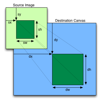
drawImage(image, dx, dy)
drawImage(image, dx, dy, dw, dh)
drawImage(image, sx, sy, sw, sh, dx, dy, dw, dh)
Each of those three can take either an
HTMLImageElement, an HTMLCanvasElement, or
an HTMLVideoElement for the image
argument.
Draws the given image onto the canvas. The arguments are
interpreted as follows:
If the first argument isn't an img,
canvas, or video element, throws a
TypeMismatchError exception. If the image has no
image data, throws an InvalidStateError exception. If
the one of the source rectangle dimensions is zero, throws an
IndexSizeError exception. If the image isn't yet
fully decoded, then nothing is drawn.
When the drawImage() method is invoked, the user
agent must run the following steps:
Check the usability of the image argument. If this
returns aborted, then an exception has been thrown and the method doesn't return anything;
abort these steps. If it returns bad, then abort these steps without drawing anything.
Otherwise it returns good; continue with these steps.
Establish the source and destination rectangles as follows:
If not specified, the dw and dh arguments must default to the values of
sw and sh, interpreted such that one CSS pixel in the image is treated as
one unit in the bitmap's coordinate space. If the sx,
sy, sw, and sh arguments are not specified, they must default to 0,
0, the image's intrinsic width in image pixels, and the image's intrinsic height in image
pixels, respectively. If the image has no intrinsic dimensions, the concrete object size
must be used instead, as determined using the CSS "Concrete Object Size Resolution"
algorithm, with the specified size having neither a definite width nor height, nor any
additional constraints, the object's intrinsic properties being those of the image
argument, and the default object size being the size of the bitmap. [CSSIMAGES]
The source rectangle is the rectangle whose corners are the four points (sx, sy), (sx+sw, sy), (sx+sw, sy+sh),
(sx, sy+sh).
The destination rectangle is the rectangle whose corners are the four points (dx, dy), (dx+dw, dy), (dx+dw, dy+dh),
(dx, dy+dh).
When the source rectangle is outside the source image, the source rectangle must be clipped
to the source image and the destination rectangle must be clipped in the same proportion.
When the destination rectangle is outside the destination image (the
bitmap), the pixels that land outside the bitmap are
discarded, as if the destination was an infinite canvas whose rendering was clipped to the
dimensions of the bitmap.
If one of the sw or sh arguments is zero, abort
these steps. Nothing is painted.
Paint the region of the image argument specified by the source rectangle
on the region of the rendering context's bitmap specified by the
destination rectangle, after applying the current
transformation matrix to the destination rectangle.
The image data must be processed in the original direction, even if the dimensions given are
negative.
This specification does not define the algorithm to
use when scaling the image, if necessary.
When a canvas is drawn onto itself, the drawing
model requires the source to be copied before the image is drawn
back onto the canvas, so it is possible to copy parts of a canvas
onto overlapping parts of itself.
If the original image data is a bitmap image, the value painted at a point in the destination
rectangle is computed by filtering the original image data. The user agent may use any filtering
algorithm (for example bilinear interpolation or nearest-neighbor). When the filtering algorithm
requires a pixel value from outside the original image data, it must instead use the value from
the nearest edge pixel. (That is, the filter uses 'clamp-to-edge' behaviour.) When the filtering
algorithm requires a pixel value from outside the source rectangle but inside the original image
data, then the value from the original image data must be used.
Thus, scaling an image in parts or in whole will have the same effect. This does
mean that when sprites coming from a single sprite sheet are to be scaled, adjacent images in
the sprite sheet can interfere. This can be avoided by ensuring each sprite in the sheet is
surrounded by a border of transparent black, or by copying sprites to be scaled into temporary
canvas elements and drawing the scaled sprites from there.
A control is a
reference to an Element node, to which, in certain
conditions, the user agent will route events, and from which the
user agent will determine the state of the hit region for the
purposes of accessibility tools. (The control is ignored when it
is not a descendant of the canvas element.)
Adds a hit region to the canvas bitmap based on the current
default path. The argument is an object with the following members:
id (default empty string)
The ID to use for this region. This is used in
MouseEvent events on the canvas (event.region) and as a way
to reference this region in later calls to addHitRegion().
control (default null)
An element (that is a descendant of the canvas)
to which events are to be routed, and which accessibility tools
are to use as a surrogate for describing and interacting with
this region.
Hit regions can be used for a variety of purposes:
With an ID, they can make hit detection easier by having the
user agent check which region the mouse is over and include the
ID in the mouse events.
With a control, they can make routing events to DOM elements
automatic, allowing e.g. clicks on a canvas to automatically
submit a form via a button element.
While both ID and control are optional, when calling
addHitRegion, at least one of the two needs to be present
to create a hit region.
Removes a hit region from the canvas
bitmap. The argument is the ID of a region added using addHitRegion().
The path that was covered by this region are effectively
cleared by this operation, leaving the regions
non-interactive. In particular, regions that occupied the same
path before the removed regions were added, do not resume their previous roles.
If there is a hit region in list whose ID
is a case-sensitive match for ID,
then return that hit region and abort these
steps.
Otherwise, return nothing.
The region representing the control control for a bitmap bitmap is the value returned by the following
algorithm (which can return a hit region or
nothing):
If control is null, return
nothing and abort these steps.
If there is a hit region in list whose control is control, then
return that hit region and abort these
steps.
Otherwise, return nothing.
The control represented by a region region for a canvas element ancestor is the value returned by the following
algorithm (which can return an element or nothing):
If region has no control, return nothing and abort these
steps.
Let specified pixels be the pixels
contained in source path.
Remove from specified pixels any pixels not contained within the clipping
region.
If the arguments object's id member is an
empty string, let it be null instead.
If the arguments object's id member is null and the arguments
object's control member is null,
throw a NotSupportedError exception and abort these steps.
If the arguments object's id member is not null, then
let previous region for this ID be the
region identified by the ID given by the id member's value in this
canvas element. If the id member is null or no such
region currently exists, let previous region for this
ID be null.
If the specified pixels has no pixels, throw a
NotSupportedError exception and abort these
steps.
Let region be a newly created hit
region, with its information configured as follows:
A user-agent-defined shape that wraps the pixels contained
in source path. (In the simplest case, this
can just be the bounding rectangle; this specification allows it
to be any shape in order to allow other interfaces.)
If the arguments object's control member is not
null: the value of the control member.
Otherwise, region has no control.
If the arguments object's control member is not
null, then let previous region for the control
be the region representing the control given by the
control member's
value for this canvas element, if any. If the control member is null
or no such region currently exists, let previous
region for the control be null.
If there is a previous region with this
control, remove it from the canvas element's
hit region list.
If the arguments object's
control member is not null, inform the user of the location of the region
representing the control
given by the control member's value for this canvas element, if any.
The full location of the corresponding fallback element, pertaining
to the control,
as represented by the region is passed to the accessibility API, if supported.
If there is a previous region with this
ID, remove it from the canvas element's hit region
list.
When the removeHitRegion()
method is invoked, the user agent must run the following steps:
Let region be the region
identified by the ID given by the method's argument in this
canvas element, if any. If no such region currently
exists, abort these steps.
If the method's argument is an empty string, then no region will match.
When the clearHitRegions()
method is invoked, the user agent must run the following steps:
Remove all hit regions
from the canvas element and clear the element's hit region list. If no regions currently
exist, abort these steps.
Calling clearRect() is a way
to clear all or some hit regions. Calling clearHitRegions()
removes all hit regions and clears the hit region list. The hit region
list itself is also reset when the rendering context is reset.
For example, when a CanvasRenderingContext2D object is
bound to or unbound from a canvas, or the dimensions of the bitmap are changed.
The MouseEvent interface is extended to support hit
regions:
The region
attribute on MouseEvent objects must return the value
it was initialized to. When the object is created, this attribute
must be initialized to null. It represents the hit region's
ID if the mouse was over a hit region when the event was
fired.
When a MouseEvent is to be fired at a
canvas element by the user agent in response to a
pointing device action, if the canvas element has a hit region list,
the user agent must instead follow these
steps. If these steps say to act as normal, that means that
the event must be fired as it would have had these requirements not
been applied.
If the pointing device is not indicating a pixel on the
canvas, act as normal and abort these steps.
If the canvas element has no hit region list, act as
normal and abort these steps.
Let pixel be the pixel indicated by the pointing device.
Let region be the hit region that is the region for the pixel pixel on this canvas element's bitmap, if any.
If there is an id, then initialize the
event object's region
attribute to id.
Dispatch the event, but with the updated event object as
given in the above steps.
This approach simplifies event handling by not
re-targeting
the event. The event is dispatched as normal once the event.region
attribute is initialized to the active hit region's ID. The event is
received by the canvas element allowing the author to define the
behavior of the event.
User agents are encouraged to make use of the information present
in a canvas element's hit region list to
improve the accessibility of canvas elements.
Each hit region should be handled in a fashion
equivalent to a node in a virtual DOM tree rooted at the
canvas element. The hierarchy of this virtual DOM tree
must match the hierarchy of the hit
regions. For each node in such a DOM tree, the hit
region's bounding circumference gives the region of the
screen to use when representing the node (if appropriate).
The semantics of a hit region for the purposes of
this virtual DOM tree are those of the hit region's
control, if it has one.
For the purposes of accessibility tools, when an element C is a descendant of a canvas element
and there is a
region representing the controlC for that
canvas element, then the element's position relative to
the document should be presented as if it was that region in the
canvas element's virtual DOM tree.
Returns an ImageData object with the given
dimensions in CSS pixels (which might map to a different number of
actual device pixels exposed by the object itself). All the pixels
in the returned object are transparent black.
Paints the data from the given ImageData object
onto the canvas. If a dirty rectangle is provided, only the pixels
from that rectangle are painted.
The globalAlpha
and globalCompositeOperation
attributes, as well as the shadow attributes, are ignored for the
purposes of this method call; pixels in the canvas are replaced
wholesale, with no composition, alpha blending, no shadows,
etc.
Throws a NotSupportedError exception if any of the
arguments are not finite.
The createImageData()
method is used to instantiate new blank ImageData
objects. When the method is invoked with two arguments sw and sh, it must return an
ImageData object representing a rectangle with a width
in CSS pixels equal to the absolute magnitude of sw and a height in CSS pixels equal to the absolute
magnitude of sh. When invoked with a single imagedata argument, it must return an
ImageData object representing a rectangle with the same
dimensions as the ImageData object passed as the
argument. The ImageData object returned must be filled
with transparent black.
The getImageData(sx, sy, sw,
sh) method must,
if the bitmap of the canvas element's origin-clean flag is set
to false, throw a SecurityError exception; otherwise, it
must return an ImageData object representing the
underlying pixel data for the area of the canvas denoted by the
rectangle whose corners are the four points (sx,
sy), (sx+sw, sy), (sx+sw, sy+sh),
(sx, sy+sh), in canvas coordinate space units. Pixels
outside the canvas must be returned as transparent black. Pixels
must be returned as non-premultiplied alpha values.
If any of the arguments to createImageData() or
getImageData()
are infinite or NaN, the method must instead throw a
NotSupportedError exception. If either the sw or sh arguments are zero,
the method must instead throw an IndexSizeError
exception.
ImageData objects must be initialized so that their
width attribute
is set to w, the number of physical device
pixels per row in the image data, their height attribute is
set to h, the number of rows in the image data,
and their data
attribute is initialized to a Uint8ClampedArray object.
The Uint8ClampedArray object must use a Canvas
Pixel ArrayBuffer for its storage, and must have
a zero start offset and a length equal to the length of its storage,
in bytes. The Canvas Pixel ArrayBuffer
must contain the image data. At least one pixel's worth of image
data must be returned. [TYPEDARRAY]
A Canvas Pixel ArrayBuffer is an
ArrayBuffer that whose data is represented in
left-to-right order, row by row top to bottom, starting with the top
left, with each pixel's red, green, blue, and alpha components being
given in that order for each pixel. Each component of each device
pixel represented in this array must be in the range 0..255,
representing the 8 bit value for that component. The components must
be assigned consecutive indices starting with 0 for the top left
pixel's red component. [TYPEDARRAY]
The putImageData(imagedata, dx, dy, dirtyX, dirtyY, dirtyWidth, dirtyHeight) method writes data from
ImageData structures back to the canvas.
If any of the arguments to the method are infinite or NaN, the
method must throw a NotSupportedError exception.
When the last four arguments are omitted, they must be assumed to
have the values 0, 0, the width member of the imagedata structure, and the height member of the imagedata structure, respectively.
When invoked with arguments that do not, per the last few
paragraphs, cause an exception to be thrown, the putImageData() method
must act as follows:
Let dxdevice be the x-coordinate
of the device pixel in the underlying pixel data of the canvas
corresponding to the dx coordinate in the
canvas coordinate space.
Let dydevice be the y-coordinate
of the device pixel in the underlying pixel data of the canvas
corresponding to the dy coordinate in the
canvas coordinate space.
If dirtyWidth is negative, let dirtyX be dirtyX+dirtyWidth, and let dirtyWidth be equal to the absolute magnitude of
dirtyWidth.
If dirtyHeight is negative, let dirtyY be dirtyY+dirtyHeight, and let dirtyHeight be equal to the absolute magnitude of
dirtyHeight.
If dirtyX is negative, let dirtyWidth be dirtyWidth+dirtyX, and
let dirtyX be zero.
If dirtyY is negative, let dirtyHeight be dirtyHeight+dirtyY, and
let dirtyY be zero.
If dirtyX+dirtyWidth is greater than the width attribute of the imagedata argument, let dirtyWidth be the value of that width attribute, minus the
value of dirtyX.
If dirtyY+dirtyHeight is greater than the height attribute of the imagedata argument, let dirtyHeight be the value of that height attribute, minus the
value of dirtyY.
If, after those changes, either dirtyWidth
or dirtyHeight is negative or zero, stop these
steps without affecting the canvas.
Otherwise, for all integer values of x
and y where dirtyX ≤ x < dirtyX+dirtyWidth
and dirtyY ≤ y < dirtyY+dirtyHeight, copy the four channels of
the pixel with coordinate (x, y) in the imagedata data
structure to the pixel with coordinate (dxdevice+x,
dydevice+y) in the underlying pixel data of the
canvas.
The handling of pixel rounding when the specified coordinates do
not exactly map to the device coordinate space is not defined by
this specification, except that the following must result in no
visible changes to the rendering:
context.putImageData(context.getImageData(x, y, w, h), p, q);
...for any value of x, y,
w, and h and where p is the smaller of x and the sum
of x and w, and q is the smaller of y and the sum
of y and h; and except that
the following two calls:
...must return ImageData objects with the same
dimensions, for any value of w and h. In other words, while user agents may round the
arguments of these methods so that they map to device pixel
boundaries, any rounding performed must be performed consistently
for all of the createImageData(), getImageData() and putImageData()
operations.
This implies that the data returned by getImageData() is at the
resolution of the canvas backing store. This is likely to not be one
device pixel to each CSS pixel if the display used is a high
resolution display.
Due to the lossy nature of converting to and from
premultiplied alpha color values, pixels that have just been set
using putImageData() might be
returned to an equivalent getImageData() as
different values.
In the following example, the script generates an
ImageData object so that it can draw onto it.
// canvas is a reference to a <canvas> element
var context = canvas.getContext('2d');

// create a blank slate
var data = context.createImageData(canvas.width, canvas.height);

// create some plasma
FillPlasma(data, 'green'); // green plasma

// add a cloud to the plasma
AddCloud(data, data.width/2, data.height/2); // put a cloud in the middle

// paint the plasma+cloud on the canvas
context.putImageData(data, 0, 0);

// support methods
function FillPlasma(data, color) { ... }
function AddCloud(data, x, y) { ... }
<!DOCTYPE HTML>
<html>
 <head>
  <title>Edge detection demo</title>
  <script>
   var image = new Image();
   function init() {
     image.onload = demo;
     image.src = "image.jpeg";
   }
   function demo() {
     var canvas = document.getElementsByTagName('canvas')[0];
     var context = canvas.getContext('2d');

     // draw the image onto the canvas
     context.drawImage(image, 0, 0);

     // get the image data to manipulate
     var input = context.getImageData(0, 0, canvas.width, canvas.height);

     // get an empty slate to put the data into
     var output = context.createImageData(canvas.width, canvas.height);

     // alias some variables for convenience
     // notice that we are using input.width and input.height here
     // as they might not be the same as canvas.width and canvas.height
     // (in particular, they might be different on high-res displays)
     var w = input.width, h = input.height;
     var inputData = input.data;
     var outputData = output.data;

     // edge detection
     for (var y = 1; y < h - 1; y += 1) {
       for (var x = 1; x < w - 1; x += 1) {
         for (var c = 0; c < 3; c += 1) {
           var i = (y*w + x)*4 + c;
           outputData[i] = 127 + -inputData[i - w*4 - 4] -   inputData[i - w*4] - inputData[i - w*4 + 4] +
                                 -inputData[i - 4]       + 8*inputData[i]       - inputData[i + 4] +
                                 -inputData[i + w*4 - 4] -   inputData[i + w*4] - inputData[i + w*4 + 4];
         }
         outputData[(y*w + x)*4 + 3] = 255; // alpha
       }
     }

     // put the image data back after manipulation
     context.putImageData(output, 0, 0);
   }
  </script>
 </head>
 <body onload="init()">
  <canvas></canvas>
 </body>
</html>
The globalAlpha
attribute gives an alpha value that is applied to shapes and images
before they are composited onto the canvas. The value must be in the
range from 0.0 (fully transparent) to 1.0 (no additional
transparency). If an attempt is made to set the attribute to a value
outside this range, including Infinity and Not-a-Number (NaN)
values, the attribute must retain its previous value. When the
context is created, the globalAlpha attribute must
initially have the value 1.0.
The globalCompositeOperation
attribute sets how shapes and images are drawn onto the existing
bitmap, once they have had globalAlpha and the
current transformation matrix applied. It must be set to a value
from the following list. In the descriptions below, the source
image, A, is the shape or image being rendered,
and the destination image, B, is the current
state of the bitmap.
source-atop
A atop B. Display the
source image wherever both images are opaque. Display the
destination image wherever the destination image is opaque but the
source image is transparent. Display transparency elsewhere.
source-in
A in B. Display the
source image wherever both the source image and destination image
are opaque. Display transparency elsewhere.
source-out
A out B. Display the
source image wherever the source image is opaque and the
destination image is transparent. Display transparency
elsewhere.
source-over (default)
A over B. Display the
source image wherever the source image is opaque. Display the
destination image elsewhere.
destination-atop
B atop A. Same as source-atop but using the
destination image instead of the source image and vice versa.
destination-in
B in A. Same as source-in but using the destination
image instead of the source image and vice versa.
destination-out
B out A. Same as source-out but using the destination
image instead of the source image and vice versa.
destination-over
B over A. Same as source-over but using the
destination image instead of the source image and vice versa.
lighter
A plus B. Display the
sum of the source image and destination image, with color values
approaching 255 (100%) as a limit.
copy
A (B is
ignored). Display the source image instead of the destination
image.
xor
A xor B. Exclusive OR
of the source image and destination image.
vendorName-operationName
Vendor-specific extensions to the list of
composition operators should use this syntax.
The operators in the above list must be treated as described by
the Porter-Duff operator given at the start of their description
(e.g. A over B). They are to
be applied as part of the drawing model, at which point the
clipping region is also applied. (Without a clipping
region, these operators act on the whole bitmap with every
operation.) [PORTERDUFF]
These values are all case-sensitive — they must be used
exactly as shown. User agents must not recognize values that are not
a case-sensitive match for one of the values given
above.
On setting, if the user agent does not recognize the specified
value, it must be ignored, leaving the value of globalCompositeOperation
unaffected.
When the context is created, the globalCompositeOperation
attribute must initially have the value
source-over.
16 Shadows
All drawing operations are affected by the four global shadow
attributes.
On setting, the new value must be parsed as a CSS
<color> value and the color assigned. If the value
cannot be parsed as a CSS <color> value then it must be
ignored, and the attribute must retain its previous value. [CSSCOLOR]
The shadowOffsetX
and shadowOffsetY
attributes specify the distance that the shadow will be offset in
the positive horizontal and positive vertical distance
respectively. Their values are in coordinate space units. They are
not affected by the current transformation matrix.
When the context is created, the shadow offset attributes must
initially have the value 0.
On getting, they must return their current value. On setting, the
attribute being set must be set to the new value, except if the
value is infinite or NaN, in which case the new value must be
ignored.
The shadowBlur
attribute specifies the level of the blurring effect. (The units do
not map to coordinate space units, and are not affected by the
current transformation matrix.)
When the context is created, the shadowBlur attribute must
initially have the value 0.
On getting, the attribute must return its current value. On
setting the attribute must be set to the new value, except if the
value is negative, infinite or NaN, in which case the new value must
be ignored.
Shadows are only drawn
if the opacity component of the alpha component of the color
of shadowColor is
non-zero and at leasty one of shadowBlur, shadowOffsetX, or shadowOffsetY is
non-zero.
It is likely that this will change: browser
vendors have indicated an interest in changing the processing model
for shadows such that they only draw when the composition operator
is "source-over" (the default). Read
more...
Perform a 2D Gaussian Blur on B,
using σ as the standard deviation.
User agents may limit values of σ to
an implementation-specific maximum value to avoid exceeding
hardware limitations during the Gaussian blur operation.
Set the red, green, and blue components of every pixel in
B to the red, green, and blue components
(respectively) of the color of shadowColor.
Multiply the alpha component of every pixel in B by the alpha component of the color of shadowColor.
The shadow is in the bitmap B, and is
rendered as part of the drawing model described below.
If the current composition operation is copy, shadows effectively won't render
(since the shape will overwrite the shadow).
17 Drawing model
When a shape or image is painted, user agents must follow these
steps, in the order given (or act as if they do):
Render the shape or image onto an infinite transparent black
bitmap, creating image A, as described in the
previous sections. For shapes, the current fill, stroke, and line
styles must be honored, and the stroke must itself also be
subjected to the current transformation matrix.
When shadows are drawn, render the shadow from
image A, using the current shadow styles,
creating image B.
Multiply the alpha component of every pixel in A by globalAlpha.
Composite A within the clipping
region over the current canvas bitmap using the current
composition operator.
18 Best practices
This section is non-normative.
When a canvas is interactive, authors should include focusable
elements in the element's fallback content corresponding to each
focusable part of the canvas.
To indicate which focusable part of the canvas is currently
focused, authors should use the drawFocusIfNeeded()
method, passing it the element for which an outline is being drawn. This
method only draws the focus outline if the element is focused, so that
it can simply be called whenever drawing the element, without
checking whether the element is focused or not first.
Authors should avoid implementing text editing controls using the
canvas element. Doing so has a large number of
disadvantages:
Mouse placement of the caret has to be reimplemented.
Keyboard movement of the caret has to be reimplemented (possibly across lines, for multiline text input).
Scrolling of the text field has to be implemented (horizontally for long lines, vertically for multiline input).
Native features such as copy-and-paste have to be reimplemented.
Native features such as spell-checking have to be reimplemented.
Native features such as drag-and-drop have to be reimplemented.
Native features such as page-wide text search have to be reimplemented.
Native features specific to the user, for example custom text
services, have to be reimplemented. This is close to impossible
since each user might have different services installed, and there
is an unbounded set of possible such services.
Bidirectional text editing has to be reimplemented.
For multiline text editing, line wrapping has to be implemented for all relevant languages.
Text selection has to be reimplemented.
Dragging of bidirectional text selections has to be reimplemented.
Platform-native keyboard shortcuts have to be reimplemented.
Platform-native input method editors (IMEs) have to be reimplemented.
Undo and redo functionality has to be reimplemented.
Accessibility features such as magnification following the
caret or selection have to be reimplemented.
This is a huge amount of work, and authors are most strongly
encouraged to avoid doing any of it by instead using the
input element, the textarea element, or
the contenteditable
attribute.
Ian Hickson; Robin Berjon; Steve Faulkner; Travis Leithead; Erika Doyle Navara; Edward O'Connor; Silvia Pfeiffer. HTML5. 28 October 2014. W3C Recommendation. URL: http://www.w3.org/TR/html5/