canvas elementwidth
height
interface HTMLCanvasElement : HTMLElement {
           attribute unsigned long width;
           attribute unsigned long height;

  DOMString toDataURL();
  DOMString toDataURL(in DOMString type);

  DOMObject getContext(in DOMString contextId);
};
The canvas element represents a
resolution-dependent bitmap canvas, which can be used for rendering
graphs, game graphics, or other visual images on the fly.
Authors should not use the canvas
element in a document when a more suitable element is available. For
example, it is inappropriate to use a canvas element to render a page heading: if the
desired presentation of the heading is graphically intense, it should be
marked up using appropriate elements (typically h1) and then styled using CSS and supporting
technologies such as XBL.
When authors use the canvas element,
they should also provide content that, when presented to the user, conveys
essentially the same function or purpose as the bitmap canvas. This
content may be placed as content of the canvas element. The contents of the canvas element, if any, are the element's fallback content.
In interactive visual media, if the canvas element is with
script, the canvas element
represents an embedded element with a dynamically created image.
In non-interactive, static, visual media, if the canvas element has been previously painted on
(e.g. if the page was viewed in an interactive visual medium and is now
being printed, or if some script that ran during the page layout process
painted on the element), then the canvas element represents embedded content with the current image and size.
Otherwise, the element represents its fallback
content instead.
In non-visual media, and in visual media if the canvas element is without
script, the canvas element
represents its fallback content instead.
The canvas element has two attributes
to control the size of the coordinate space: width and height. These attributes, when
specified, must have values that are valid non-negative integers. The rules for parsing non-negative integers must be used to
obtain their numeric values. If an attribute is missing, or if parsing its
value returns an error, then the default value must be used instead. The
width attribute
defaults to 300, and the height attribute defaults to 150.
The intrinsic dimensions of the canvas element equal the size of the coordinate
space, with the numbers interpreted in CSS pixels. However, the element
can be sized arbitrarily by a style sheet. During rendering, the image is
scaled to fit this layout size.
The size of the coordinate space does not necessarily represent the size of the actual bitmap that the user agent will use internally or during rendering. On high-definition displays, for instance, the user agent may internally use a bitmap with two device pixels per unit in the coordinate space, so that the rendering remains at high quality throughout.
Whenever the width and height attributes are set (whether to a new
value or to the previous value), the bitmap and any associated contexts
must be cleared back to their initial state and reinitialized with the
newly specified coordinate space dimensions.
The width and
height DOM
attributes must reflect the content attributes of
the same name.
Only one square appears to be drawn in the following example:
  // canvas is a reference to a <canvas> element
  var context = canvas.getContext('2d');
  context.fillRect(0,0,50,50);
  canvas.setAttribute('width', '300'); // clears the canvas
  context.fillRect(0,100,50,50);
  canvas.width = canvas.width; // clears the canvas
  context.fillRect(100,0,50,50); // only this square remains
When the canvas is initialized it must be set to fully transparent black.
To draw on the canvas, authors must first obtain a reference to a context using the getContext(contextId) method of the canvas element.
This specification only defines one context, with the name "2d". If getContext()
is called with that exact string for its contextId
argument, then the UA must return a reference to an object implementing
CanvasRenderingContext2D.
Other specifications may define their own contexts, which would return
different objects.
Vendors may also define experimental contexts using the syntax
vendorname-context,
for example, moz-3d.
When the UA is passed an empty string or a string specifying a context that it does not support, then it must return null. String comparisons must be literal and case-sensitive.
Arguments other than the contextId must be ignored, and must not cause the user agent to raise an exception (as would normally occur if a method was called with the wrong number of arguments).
A future version of this specification will probably define a
3d context (probably based on the OpenGL ES API).
The toDataURL() method must,
when called with no arguments, return a data: URI
containing a representation of the image as a PNG file. [PNG].
If the canvas has no pixels (i.e. either its horizontal dimension or its
vertical dimension is zero) then the method must return the string "data:,". (This is the shortest data:
URI; it represents the empty string in a text/plain
resource.)
The toDataURL(type) method (when called with one or
more arguments) must return a data: URI
containing a representation of the image in the format given by type. The possible values are MIME types with no
parameters, for example image/png, image/jpeg,
or even maybe image/svg+xml if the implementation actually
keeps enough information to reliably render an SVG image from the canvas.
Only support for image/png is required. User agents may
support other types. If the user agent does not support the requested
type, it must return the image using the PNG format.
User agents must convert the provided type to lower case before
establishing if they support that type and before creating the data: URI.
When trying to use types other than image/png,
authors can check if the image was really returned in the requested format
by checking to see if the returned string starts with one the exact
strings "data:image/png," or "data:image/png;". If it does, the image is PNG, and thus
the requested type was not supported. (The one exception to this is if the
canvas has either no height or no width, in which case the result might
simply be "data:,".)
Arguments other than the type must be ignored, and
must not cause the user agent to raise an exception (as would normally
occur if a method was called with the wrong number of arguments). A future
version of this specification will probably allow extra parameters to be
passed to toDataURL() to allow authors to more
carefully control compression settings, image metadata, etc.
When the getContext() method of a canvas element is invoked with 2d as the argument, a CanvasRenderingContext2D
object is returned.
There is only one CanvasRenderingContext2D
object per canvas, so calling the getContext() method with the 2d argument a second time
must return the same object.
The 2D context represents a flat Cartesian surface whose origin (0,0) is at the top left corner, with the coordinate space having x values increasing when going right, and y values increasing when going down.
interface CanvasRenderingContext2D {

  // back-reference to the canvas
  readonly attribute HTMLCanvasElement canvas;

  // state
  void save(); // push state on state stack
  void restore(); // pop state stack and restore state

  // transformations (default transform is the identity matrix)
  void scale(in float x, in float y);
  void rotate(in float angle);
  void translate(in float x, in float y);
  void transform(in float m11, in float m12, in float m21, in float m22, in float dx, in float dy);
  void setTransform(in float m11, in float m12, in float m21, in float m22, in float dx, in float dy);

  // compositing
           attribute float globalAlpha; // (default 1.0)
           attribute DOMString globalCompositeOperation; // (default source-over)

  // colors and styles
           attribute DOMObject strokeStyle; // (default black)
           attribute DOMObject fillStyle; // (default black)
  CanvasGradient createLinearGradient(in float x0, in float y0, in float x1, in float y1);
  CanvasGradient createRadialGradient(in float x0, in float y0, in float r0, in float x1, in float y1, in float r1);
  CanvasPattern createPattern(in HTMLImageElement image, in DOMString repetition);
  CanvasPattern createPattern(in HTMLCanvasElement image, in DOMString repetition);

  // line caps/joins
           attribute float lineWidth; // (default 1)
           attribute DOMString lineCap; // "butt", "round", "square" (default "butt")
           attribute DOMString lineJoin; // "round", "bevel", "miter" (default "miter")
           attribute float miterLimit; // (default 10)

  // shadows
           attribute float shadowOffsetX; // (default 0)
           attribute float shadowOffsetY; // (default 0)
           attribute float shadowBlur; // (default 0)
           attribute DOMString shadowColor; // (default transparent black)

  // rects
  void clearRect(in float x, in float y, in float w, in float h);
  void fillRect(in float x, in float y, in float w, in float h);
  void strokeRect(in float x, in float y, in float w, in float h);

  // path API
  void beginPath();
  void closePath();
  void moveTo(in float x, in float y);
  void lineTo(in float x, in float y);
  void quadraticCurveTo(in float cpx, in float cpy, in float x, in float y);
  void bezierCurveTo(in float cp1x, in float cp1y, in float cp2x, in float cp2y, in float x, in float y);
  void arcTo(in float x1, in float y1, in float x2, in float y2, in float radius);
  void rect(in float x, in float y, in float w, in float h);
  void arc(in float x, in float y, in float radius, in float startAngle, in float endAngle, in boolean anticlockwise);
  void fill();
  void stroke();
  void clip();
  boolean isPointInPath(in float x, in float y);

  // text
           attribute DOMString font; // (default 10px sans-serif)
           attribute DOMString textAlign; // "start", "end", "left", "right", "center" (default: "start")
           attribute DOMString textBaseline; // "top", "hanging", "middle", "alphabetic", "ideographic", "bottom" (default: "alphabetic")
  void fillText(in DOMString text, in float x, in float y);
  void fillText(in DOMString text, in float x, in float y, in float maxWidth);
  void strokeText(in DOMString text, in float x, in float y);
  void strokeText(in DOMString text, in float x, in float y, in float maxWidth);
  TextMetrics measureText(in DOMString text);

  // drawing images
  void drawImage(in HTMLImageElement image, in float dx, in float dy);
  void drawImage(in HTMLImageElement image, in float dx, in float dy, in float dw, in float dh);
  void drawImage(in HTMLImageElement image, in float sx, in float sy, in float sw, in float sh, in float dx, in float dy, in float dw, in float dh);
  void drawImage(in HTMLCanvasElement image, in float dx, in float dy);
  void drawImage(in HTMLCanvasElement image, in float dx, in float dy, in float dw, in float dh);
  void drawImage(in HTMLCanvasElement image, in float sx, in float sy, in float sw, in float sh, in float dx, in float dy, in float dw, in float dh);

  // pixel manipulation
  ImageData createImageData(in float sw, in float sh);
  ImageData getImageData(in float sx, in float sy, in float sw, in float sh);
  void putImageData(in ImageData imagedata, in float dx, in float dy);
  void putImageData(in ImageData imagedata, in float dx, in float dy, in float dirtyX, in float dirtyY, in float dirtyWidth, in float dirtyHeight);
};

interface CanvasGradient {
  // opaque object
  void addColorStop(in float offset, in DOMString color);
};

interface CanvasPattern {
  // opaque object
};

interface TextMetrics {
  readonly attribute float width;
};

interface ImageData {
  readonly attribute long int width;
  readonly attribute long int height;
  readonly attribute int[] data;
};
The canvas attribute must
return the canvas element that the
context paints on.
Unless otherwise stated, for the 2D context interface, any method call with a numeric argument whose value is infinite or a NaN value must be ignored.
Each context maintains a stack of drawing states. Drawing states consist of:
strokeStyle, fillStyle,
globalAlpha, lineWidth,
lineCap,
lineJoin, miterLimit, shadowOffsetX, shadowOffsetY, shadowBlur, shadowColor, globalCompositeOperation,
font, textAlign,
textBaseline.
The current path and the current bitmap are not part of the
drawing state. The current path is persistent, and can only be reset using
the beginPath() method. The current bitmap is
a property of the
canvas, not the context.
The save()
method must push a copy of the current drawing state onto the drawing
state stack.
The restore() method must pop
the top entry in the drawing state stack, and reset the drawing state it
describes. If there is no saved state, the method must do nothing.
The transformation matrix is applied to coordinates when creating shapes and paths.
When the context is created, the transformation matrix must initially be the identity transform. It may then be adjusted using the transformation methods.
The transformations must be performed in reverse order. For instance, if a scale transformation that doubles the width is applied, followed by a rotation transformation that rotates drawing operations by a quarter turn, and a rectangle twice as wide as it is tall is then drawn on the canvas, the actual result will be a square.
The scale(x, y) method must add the
scaling transformation described by the arguments to the transformation
matrix. The x argument represents the scale factor in
the horizontal direction and the y argument represents
the scale factor in the vertical direction. The factors are multiples.
The rotate(angle) method must add the rotation
transformation described by the argument to the transformation matrix. The
angle argument represents a clockwise rotation angle
expressed in radians. If the angle argument is
infinite, the method call must be ignored.
The translate(x, y) method must add the translation
transformation described by the arguments to the transformation matrix.
The x argument represents the translation distance in
the horizontal direction and the y argument represents
the translation distance in the vertical direction. The arguments are in
coordinate space units.
The transform(m11,
m12, m21, m22,
dx, dy) method must
multiply the current transformation matrix with the matrix described by:
| m11 | m21 | dx |
| m12 | m22 | dy |
| 0 | 0 | 1 |
The setTransform(m11, m12, m21, m22, dx, dy) method must reset the current transform to
the identity matrix, and then invoke the transform(m11, m12, m21, m22, dx, dy) method with the same
arguments.
All drawing operations are affected by the global compositing
attributes, globalAlpha and globalCompositeOperation.
The globalAlpha attribute
gives an alpha value that is applied to shapes and images before they are
composited onto the canvas. The value must be in the range from 0.0 (fully
transparent) to 1.0 (no additional transparency). If an attempt is made to
set the attribute to a value outside this range, the attribute must retain
its previous value. When the context is created, the globalAlpha attribute must initially have
the value 1.0.
The globalCompositeOperation
attribute sets how shapes and images are drawn onto the existing bitmap,
once they have had globalAlpha and the current transformation
matrix applied. It must be set to a value from the following list. In the
descriptions below, the source image, A, is the shape
or image being rendered, and the destination image, B,
is the current state of the bitmap.
source-atop
source-in
source-out
source-over (default)
destination-atop
source-atop but
using the destination image instead of the source image and vice versa.
destination-in
source-in but using
the destination image instead of the source image and vice versa.
destination-out
source-out but
using the destination image instead of the source image and vice versa.
destination-over
source-over but
using the destination image instead of the source image and vice versa.lighter
copy
xor
vendorName-operationName
These values are all case-sensitive — they must be used exactly as shown. User agents must not recognize values that do not exactly match the values given above.
The operators in the above list must be treated as described by the Porter-Duff operator given at the start of their description (e.g. A over B). [PORTERDUFF]
On setting, if the user agent does not recognize the specified value, it
must be ignored, leaving the value of globalCompositeOperation
unaffected.
When the context is created, the globalCompositeOperation
attribute must initially have the value source-over.
The strokeStyle attribute
represents the color or style to use for the lines around shapes, and the
fillStyle attribute
represents the color or style to use inside the shapes.
Both attributes can be either strings, CanvasGradients, or CanvasPatterns. On setting, strings must
be parsed as CSS <color> values and the color assigned, and CanvasGradient and CanvasPattern objects must be assigned
themselves. [CSS3COLOR] If the value is a
string but is not a valid color, or is neither a string, a CanvasGradient, nor a CanvasPattern, then it must be ignored,
and the attribute must retain its previous value.
On getting, if the value is a color, then the serialization of the color must be
returned. Otherwise, if it is not a color but a CanvasGradient or CanvasPattern, then the respective
object must be returned. (Such objects are opaque and therefore only
useful for assigning to other attributes or for comparison to other
gradients or patterns.)
The serialization of a color for a color
value is a string, computed as follows: if it has alpha equal to 1.0, then
the string is a lowercase six-digit hex value, prefixed with a "#"
character (U+0023 NUMBER SIGN), with the first two digits representing the
red component, the next two digits representing the green component, and
the last two digits representing the blue component, the digits being in
the range 0-9 a-f (U+0030 to U+0039 and U+0061 to U+0066). Otherwise, the
color value has alpha less than 1.0, and the string is the color value in
the CSS rgba() functional-notation format: the
literal string rgba (U+0072 U+0067 U+0062 U+0061)
followed by a U+0028 LEFT PARENTHESIS, a base-ten integer in the range
0-255 representing the red component (using digits 0-9, U+0030 to U+0039,
in the shortest form possible), a literal U+002C COMMA and U+0020 SPACE,
an integer for the green component, a comma and a space, an integer for
the blue component, another comma and space, a U+0030 DIGIT ZERO, a U+002E
FULL STOP (representing the decimal point), one or more digits in the
range 0-9 (U+0030 to U+0039) representing the fractional part of the alpha
value, and finally a U+0029 RIGHT PARENTHESIS.
When the context is created, the strokeStyle and fillStyle
attributes must initially have the string value #000000.
There are two types of gradients, linear gradients and radial gradients,
both represented by objects implementing the opaque CanvasGradient interface.
Once a gradient has been created (see below), stops are placed along it to define how the colors are distributed along the gradient. The color of the gradient at each stop is the color specified for that stop. Between each such stop, the colors and the alpha component must be linearly interpolated over the RGBA space without premultiplying the alpha value to find the color to use at that offset. Before the first stop, the color must be the color of the first stop. After the last stop, the color must be the color of the last stop. When there are no stops, the gradient is transparent black.
The addColorStop(offset, color) method on
the CanvasGradient interface
adds a new stop to a gradient. If the offset is less
than 0, greater than 1, infinite, or NaN, then an
INDEX_SIZE_ERR exception must be raised. If the color cannot be parsed as a CSS color, then a
SYNTAX_ERR exception must be raised. Otherwise, the gradient
must have a new stop placed, at offset offset relative
to the whole gradient, and with the color obtained by parsing color as a CSS <color> value. If multiple stops are
added at the same offset on a gradient, they must be placed in the order
added, with the first one closest to the start of the gradient, and each
subsequent one infinitesimally further along towards the end point (in
effect causing all but the first and last stop added at each point to be
ignored).
The createLinearGradient(x0, y0, x1, y1) method takes four arguments that, after
being subjected to the current transformation matrix,
represent the start point (x0, y0)
and end point (x1, y1) of the
gradient. If any of the arguments to createLinearGradient() are
infinite or NaN, the method must raise an INDEX_SIZE_ERR
exception. Otherwise, the method must return a linear CanvasGradient initialized with the
specified line.
Linear gradients must be rendered such that at and before the starting point on the canvas the color at offset 0 is used, that at and after the ending point the color at offset 1 is used, and that all points on a line perpendicular to the line that crosses the start and end points have the color at the point where those two lines cross (with the colors coming from the interpolation described above).
If x0 = x1 and y0 = y1, then the linear gradient must paint nothing.
The createRadialGradient(x0, y0, r0, x1, y1, r1) method takes six arguments, the first
three representing the start circle with origin (x0,
y0) and radius r0, and the last
three representing the end circle with origin (x1,
y1) and radius r1. The values are
in coordinate space units. If either of r0 or r1 are negative, or if any of the arguments are infinite or
NaN, an INDEX_SIZE_ERR exception must be raised. Otherwise,
the method must return a radial CanvasGradient initialized with the two
specified circles, after transforming them according to the current
transformation matrix.
Radial gradients must be rendered by following these steps:
If x0 = x1 and y0 = y1 and r0 = r1, then the radial gradient must paint nothing. Abort these steps.
Let x(ω) = (x1-x0)ω + x0
Let y(ω) = (y1-y0)ω + y0
Let r(ω) = (r1-r0)ω + r0
Let the color at ω be the color of the gradient at offset 0.0 for all values of ω less than 0.0, the color at offset 1.0 for all values of ω greater than 1.0, and the color at the given offset for values of ω in the range 0.0 ≤ ω ≤ 1.0
For all values of ω where r(ω) > 0, starting with the value of ω nearest to positive infinity and ending with the value of ω nearest to negative infinity, draw the circumference of the circle with radius r(ω) at position (x(ω), y(ω)), with the color at ω, but only painting on the parts of the canvas that have not yet been painted on by earlier circles in this step for this rendering of the gradient.
This effectively creates a cone, touched by the two circles defined in the creation of the gradient, with the part of the cone before the start circle (0.0) using the color of the first offset, the part of the cone after the end circle (1.0) using the color of the last offset, and areas outside the cone untouched by the gradient (transparent black).
Gradients must be painted only where the relevant stroking or filling effects requires that they be drawn.
Patterns are represented by objects implementing the opaque CanvasPattern interface.
To create objects of this type, the createPattern(image, repetition) method
is used. The first argument gives the image to use as the pattern (either
an HTMLImageElement or an
HTMLCanvasElement).
Modifying this image after calling the createPattern() method must not affect
the pattern. The second argument must be a string with one of the
following values: repeat, repeat-x, repeat-y, no-repeat. If the empty string or null is specified, repeat must be assumed. If an unrecognized value is given,
then the user agent must raise a SYNTAX_ERR exception. User
agents must recognize the four values described above exactly (e.g. they
must not do case folding). The method must return a CanvasPattern object suitably
initialized.
The image argument must be an instance of an
HTMLImageElement or HTMLCanvasElement. If the image is of the wrong type or null, the implementation must
raise a TYPE_MISMATCH_ERR exception.
If the image argument is an HTMLImageElement object whose complete attribute
is false, then the implementation must raise an
INVALID_STATE_ERR exception.
If the image argument is an HTMLCanvasElement object with either
a horizontal dimension or a vertical dimension equal to zero, then the
implementation must raise an INVALID_STATE_ERR exception.
Patterns must be painted so that the top left of the first image is
anchored at the origin of the coordinate space, and images are then
repeated horizontally to the left and right (if the repeat-x
string was specified) or vertically up and down (if the
repeat-y string was specified) or in all four directions all
over the canvas (if the repeat string was specified). The
images are not scaled by this process; one CSS pixel of the image must be
painted on one coordinate space unit. Of course, patterns must actually be
painted only where the stroking or filling effect requires that they be
drawn, and are affected by the current transformation matrix.
When the createPattern() method is passed, as its
image argument, an animated image, the poster frame of
the animation, or the first frame of the animation if there is no poster
frame, must be used.
Support for patterns is optional. If the user agent doesn't support
patterns, then createPattern() must return null.
The lineWidth attribute
gives the width of lines, in coordinate space units. On setting, zero,
negative, infinite, and NaN values must be ignored, leaving the value
unchanged.
When the context is created, the lineWidth attribute must initially have the
value 1.0.
The lineCap attribute defines
the type of endings that UAs will place on the end of lines. The three
valid values are butt, round, and
square. The butt value means that the end of
each line is a flat edge perpendicular to the direction of the line. The
round value means that a semi-circle with the diameter equal
to the width of the line must then be added on to the end of the line. The
square value means that a rectangle with the length of the
line width and the width of half the line width, placed flat against the
edge perpendicular to the direction of the line, must be added at the end
of each line. On setting, any other value than the literal strings
butt, round, and square must be
ignored, leaving the value unchanged.
When the context is created, the lineCap attribute must initially have the value
butt.
The lineJoin attribute
defines the type of corners that UAs will place where two lines meet. The
three valid values are bevel, round, and
miter.
On setting, any other value than the literal strings bevel,
round, and miter must be ignored, leaving the
value unchanged.
When the context is created, the lineJoin attribute must initially have the
value miter.
A join exists at any point in a subpath shared by two consecutive lines. When a subpath is closed, then a join also exists at its first point (equivalent to its last point) connecting the first and last lines in the subpath.
In addition to the point where the join occurs, two additional points are relevant to each join, one for each line: the two corners found half the line width away from the join point, one perpendicular to each line, each on the side furthest from the other line.
A filled triangle connecting these two opposite corners with a straight
line, with the third point of the triangle being the join point, must be
rendered at all joins. The lineJoin attribute controls whether anything
else is rendered. The three aforementioned values have the following
meanings:
The bevel value means that this is all that is rendered at
joins.
The round value means that a filled arc connecting the two
aforementioned corners of the join, abutting (and not overlapping) the
aforementioned triangle, with the diameter equal to the line width and the
origin at the point of the join, must be rendered at joins.
The miter value means that a second filled triangle must
(if it can given the miter length) be rendered at the join, with one line
being the line between the two aforementioned corners, abutting the first
triangle, and the other two being continuations of the outside edges of
the two joining lines, as long as required to intersect without going over
the miter length.
The miter length is the distance from the point where the lines touch on the inside of the join to the intersection of the line edges on the outside of the join. The miter limit ratio is the maximum allowed ratio of the length of the two continuation lines to the line width. If the miter length would be exceeded, this second triangle must not be rendered.
The miter limit ratio can be explicitly set using the miterLimit attribute.
On setting, zero, negative, infinite, and NaN values must be ignored,
leaving the value unchanged.
When the context is created, the miterLimit attribute must initially have the
value 10.0.
All drawing operations are affected by the four global shadow attributes.
The shadowColor attribute
sets the color of the shadow.
When the context is created, the shadowColor attribute initially must be
fully-transparent black.
On getting, the serialization of the color must be returned.
On setting, the new value must be parsed as a CSS <color> value and the color assigned. If the value is not a valid color, then it must be ignored, and the attribute must retain its previous value. [CSS3COLOR]
The shadowOffsetX and
shadowOffsetY
attributes specify the distance that the shadow will be offset in the
positive horizontal and positive vertical distance respectively. Their
values are in coordinate space units. They are not affected by the current
transformation matrix.
When the context is created, the shadow offset attributes initially have
the value 0.
On getting, they must return their current value. On setting, the attribute being set must be set to the new value, except if the value is infinite or NaN, in which case the new value must be ignored.
The shadowBlur attribute
specifies the size of the blurring effect. (The units do not map to
coordinate space units, and are not affected by the current transformation
matrix.)
When the context is created, the shadowBlur attribute must initially have the
value 0.
On getting, the attribute must return its current value. On setting the attribute must be set to the new value, except if the value is negative, infinite or NaN, in which case the new value must be ignored.
Support for shadows is optional. When they are supported, then, when shadows are drawn, they must be rendered as follows:
Let A be the source image for which a shadow is being created.
Let B be an infinite transparent black bitmap, with a coordinate space and an origin identical to A.
Copy the alpha channel of A to B, offset by shadowOffsetX in the positive x direction, and shadowOffsetY in the positive y direction.
If shadowBlur is greater than 0:
If shadowBlur is less than 8, let σ be half the value of shadowBlur; otherwise, let σ be the square root of multiplying the value of
shadowBlur by 2.
Perform a 2D Gaussian Blur on B, using σ as the standard deviation.
User agents may limit values of σ to an implementation-specific maximum value to avoid exceeding hardware limitations during the Gaussian blur operation.
Set the red, green, and blue components of every pixel in B to the red, green, and blue components (respectively)
of the color of shadowColor.
Multiply the alpha component of every pixel in B
by the alpha component of the color of shadowColor.
The shadow is in the bitmap B, and is rendered as part of the drawing model described below.
There are three methods that immediately draw rectangles to the bitmap. They each take four arguments; the first two give the x and y coordinates of the top left of the rectangle, and the second two give the width w and height h of the rectangle, respectively.
The current transformation matrix must be applied to the following four coordinates, which form the path that must then be closed to get the specified rectangle: (x, y), (x+w, y), (x+w, y+h), (x, y+h).
Shapes are painted without affecting the current path, and are subject
to the clipping region,
and, with the exception of clearRect(), also shadow effects, global alpha, and global composition
operators.
The clearRect(x, y, w, h) method must clear the pixels in the
specified rectangle that also intersect the current clipping region to a
fully transparent black, erasing any previous image. If either height or
width are zero, this method has no effect.
The fillRect(x, y, w, h) method must paint the specified rectangular
area using the fillStyle. If either height or width are
zero, this method has no effect.
The strokeRect(x,
y, w, h) method must stroke the specified
rectangle's path using the strokeStyle, lineWidth,
lineJoin, and (if appropriate) miterLimit attributes. If both height and
width are zero, this method has no effect, since there is no path to
stroke (it's a point). If only one of the two is zero, then the method
will draw a line instead (the path for the outline is just a straight line
along the non-zero dimension).
The context always has a current path. There is only one current path, it is not part of the drawing state.
A path has a list of zero or more subpaths. Each subpath consists of a list of one or more points, connected by straight or curved lines, and a flag indicating whether the subpath is closed or not. A closed subpath is one where the last point of the subpath is connected to the first point of the subpath by a straight line. Subpaths with fewer than two points are ignored when painting the path.
Initially, the context's path must have zero subpaths.
The points and lines added to the path by these methods must be transformed according to the current transformation matrix as they are added.
The beginPath() method must
empty the list of subpaths so that the context once again has zero
subpaths.
The moveTo(x, y) method must create a
new subpath with the specified point as its first (and only) point.
The closePath() method must
do nothing if the context has no subpaths. Otherwise, it must mark the
last subpath as closed, create a new subpath whose first point is the same
as the previous subpath's first point, and finally add this new subpath to
the path. (If the last subpath had more than one point in its list of
points, then this is equivalent to adding a straight line connecting the
last point back to the first point, thus "closing" the shape, and then
repeating the last moveTo() call.)
New points and the lines connecting them are added to subpaths using the methods described below. In all cases, the methods only modify the last subpath in the context's paths.
The lineTo(x, y) method must do
nothing if the context has no subpaths. Otherwise, it must connect the
last point in the subpath to the given point (x, y) using a straight line, and must then add the given point
(x, y) to the subpath.
The quadraticCurveTo(cpx, cpy, x, y) method must do nothing if the context has
no subpaths. Otherwise it must connect the last point in the subpath to
the given point (x, y) using a
quadratic Bézier curve with control point (cpx,
cpy), and must then add the given point (x, y) to the subpath. [BEZIER]
The bezierCurveTo(cp1x, cp1y, cp2x,
cp2y, x, y) method must do nothing if the context has
no subpaths. Otherwise, it must connect the last point in the subpath to
the given point (x, y) using a
cubic Bézier curve with control points (cp1x,
cp1y) and (cp2x, cp2y). Then, it must add the point (x,
y) to the subpath. [BEZIER]
The arcTo(x1, y1, x2, y2, radius) method must do
nothing if the context has no subpaths. If the context does have
a subpath, then the behavior depends on the arguments and the last point
in the subpath.
Negative values for radius must cause the
implementation to raise an INDEX_SIZE_ERR exception.
Let the point (x0, y0) be the last point in the subpath.
If the point (x0, y0) is equal to the point (x1, y1), or if the point (x1, y1) is equal to the point (x2, y2), then the method must add the point (x1, y1) to the subpath, and connect that point to the previous point (x0, y0) by a straight line.
Otherwise, if the points (x0, y0), (x1, y1), and (x2, y2) all lie on a single straight line, then: if the direction from (x0, y0) to (x1, y1) is the same as the direction from (x1, y1) to (x2, y2), then method must add the point (x1, y1) to the subpath, and connect that point to the previous point (x0, y0) by a straight line; otherwise, the direction from (x0, y0) to (x1, y1) is the opposite of the direction from (x1, y1) to (x2, y2), and the method must add a point (x∞, y∞) to the subpath, and connect that point to the previous point (x0, y0) by a straight line, where (x∞, y∞) is the point that is infinitely far away from (x1, y1), that lies on the same line as (x0, y0), (x1, y1), and (x2, y2), and that is on the same side of (x1, y1) on that line as (x2, y2).
Otherwise, let The Arc be the shortest arc given by circumference of the circle that has radius radius, and that has one point tangent to the half-infinite line that crosses the point (x0, y0) and ends at the point (x1, y1), and that has a different point tangent to the half-infinite line that ends at the point (x1, y1) and crosses the point (x2, y2). The points at which this circle touches these two lines are called the start and end tangent points respectively.
The method must connect the point (x0, y0) to the start tangent point by a straight line, adding the start tangent point to the subpath, and then must connect the start tangent point to the end tangent point by The Arc, adding the end tangent point to the subpath.
The arc(x, y, radius, startAngle, endAngle, anticlockwise) method draws an arc. If the
context has any subpaths, then the method must add a straight line from
the last point in the subpath to the start point of the arc. In any case,
it must draw the arc between the start point of the arc and the end point
of the arc, and add the start and end points of the arc to the subpath.
The arc and its start and end points are defined as follows:
Consider a circle that has its origin at (x, y) and that has radius radius. The points at startAngle and endAngle along the circle's circumference, measured in radians clockwise from the positive x-axis, are the start and end points respectively. The arc is the path along the circumference of this circle from the start point to the end point, going anti-clockwise if the anticlockwise argument is true, and clockwise otherwise. Since the points are on the circle, as opposed to being simply angles from zero, the arc can never cover an angle greater than 2π radians. If the two angles are equal, or if the radius is zero, then the arc is defined as being of zero length in both directions.
Negative values for radius must cause the
implementation to raise an INDEX_SIZE_ERR exception.
The rect(x, y, w, h) method must create a new subpath containing
just the four points (x, y), (x+w, y), (x+w, y+h), (x, y+h), with those four points connected by straight lines, and
must then mark the subpath as closed. It must then create a new subpath
with the point (x, y) as the only
point in the subpath.
The fill()
method must fill all the subpaths of the current path, using fillStyle,
and using the non-zero winding number rule. Open subpaths must be
implicitly closed when being filled (without affecting the actual
subpaths).
Thus, if two overlapping but otherwise independent subpaths have opposite windings, they cancel out and result in no fill. If they have the same winding, that area just gets painted once.
The stroke() method must
calculate the strokes of all the subpaths of the current path, using the
lineWidth, lineCap, lineJoin, and
(if appropriate) miterLimit attributes, and then fill the
combined stroke area using the strokeStyle, attribute.
Since the subpaths are all stroked as one, overlapping parts of the paths in one stroke operation are treated as if their union was what was painted.
Paths, when filled or stroked, must be painted without affecting the current path, and must be subject to shadow effects, global alpha, the clipping region, and global composition operators. (Transformations affect the path when the path is created, not when it is painted, though the stroke style is still affected by the transformation during painting.)
Zero-length line segments must be pruned before stroking a path. Empty subpaths must be ignored.
The clip()
method must create a new clipping region by
calculating the intersection of the current clipping region and the area
described by the current path, using the non-zero winding number rule.
Open subpaths must be implicitly closed when computing the clipping
region, without affecting the actual subpaths. The new clipping region
replaces the current clipping region.
When the context is initialized, the clipping region must be set to the rectangle with the top left corner at (0,0) and the width and height of the coordinate space.
The isPointInPath(x, y) method must return
true if the point given by the x and y coordinates passed to the method, when treated as
coordinates in the canvas coordinate space unaffected by the current
transformation, is inside the current path; and must return false
otherwise. Points on the path itself are considered to be inside the path.
If either of the arguments is infinite or NaN, then the method must return
false.
The font DOM
attribute, on setting, must be parsed the same way as the 'font' property
of CSS (but without supporting property-independent stylesheet syntax like
'inherit'), and the resulting font must be assigned to the context, with
the 'line-height' component forced to 'normal'. [CSS]
Font names must be interpreted in the context of the canvas element's stylesheets; any fonts embedded
using @font-face must therefore be available. [CSSWEBFONTS]
Only vector fonts should be used by the user agent; if a user agent were to use bitmap fonts then transformations would likely make the font look very ugly.
On getting, the font attribute must return the serialized form of
the current font of the context. [CSSOM]
When the context is created, the font of the context must be set to 10px
sans-serif. When the 'font-size' component is set to lengths using
percentages, 'em' or 'ex' units, or the 'larger' or 'smaller' keywords,
these must be interpreted relative to the computed value of the
'font-size' property of the corresponding canvas element. When the 'font-weight' component
is set to the relative values 'bolder' and 'lighter', these must be
interpreted relative to the computed value of the 'font-weight' property
of the corresponding canvas element.
The textAlign DOM attribute,
on getting, must return the current value. On setting, if the value is one
of start, end, left, right, or center, then the value must be changed to the new value.
Otherwise, the new value must be ignored. When the context is created, the
textAlign attribute must initially have the
value start.
The textBaseline DOM
attribute, on getting, must return the current value. On setting, if the
value is one of top, hanging, middle, alphabetic, ideographic, or bottom, then the value must be changed to the
new value. Otherwise, the new value must be ignored. When the context is
created, the textBaseline attribute must initially have
the value alphabetic.
The textBaseline attribute's allowed keywords
correspond to alignment points in the font:
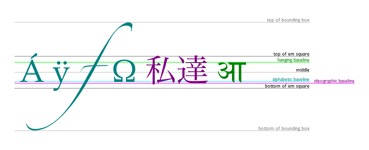
The keywords map to these alignment points as follows:
top
hanging
middle
alphabetic
ideographic
bottom
The fillText() and strokeText() methods
take three or four arguments, text, x, y, and optionally maxWidth, and render the given text at
the given (x, y) coordinates
ensuring that the text isn't wider than maxWidth if
specified, using the current font, textAlign, and textBaseline values. Specifically, when
the methods are called, the user agent must run the following steps:
Let font be the current font of the browsing
context, as given by the font attribute.
Replace all the space characters in text with U+0020 SPACE characters.
Form a hypothetical infinitely wide CSS line box containing a single
inline box containing the text text, with all the
properties at their initial values except the 'font' property of the
inline element set to font and the 'direction'
property of the inline element set to the 'direction' property of the
canvas element. [CSS]
If the maxWidth argument was specified and the hypothetical width of the inline box in the hypothetical line box is greater than maxWidth CSS pixels, then change font to have a more condensed font (if one is available or if a reasonably readable one can be synthesized by applying a horizontal scale factor to the font) or a smaller font, and return to the previous step.
Let the anchor point be a point on the inline box,
determined by the textAlign and textBaseline values, as follows:
Horizontal position:
textAlign is left
textAlign is start
and the 'direction' property on the canvas element has a computed value of 'ltr'
textAlign is end and
the 'direction' property on the canvas element has a computed value of 'rtl'
textAlign is right
textAlign is end and
the 'direction' property on the canvas element has a computed value of 'ltr'
textAlign is start
and the 'direction' property on the canvas element has a computed value of 'rtl'
textAlign is center
Vertical position:
textBaseline is top
textBaseline is hanging
textBaseline is middle
textBaseline is alphabetic
textBaseline is ideographic
textBaseline is bottom
Paint the hypothetical inline box as the shape given by the text's glyphs, as transformed by the current transformation matrix, and anchored and sized so that before applying the current transformation matrix, the anchor point is at (x, y) and each CSS pixel is mapped to one coordinate space unit.
For fillText() fillStyle
must be applied to the glyphs and strokeStyle must be ignored. For strokeText() the reverse holds and strokeStyle must be applied to the glyph
outlines and fillStyle must be ignored.
Text is painted without affecting the current path, and is subject to shadow effects, global alpha, the clipping region, and global composition operators.
The measureText() method
takes one argument, text. When the method is invoked,
the user agent must replace all the space characters in text with U+0020
SPACE characters, and then must form a hypothetical infinitely wide CSS
line box containing a single inline box containing the text text, with all the properties at their initial values
except the 'font' property of the inline element set to the current font
of the browsing context, as given by the font attribute, and
must then return a new TextMetrics
object with its width attribute set to the width of that inline
box, in CSS pixels. [CSS]
The TextMetrics interface is
used for the objects returned from measureText(). It has one attribute, width, which is
set by the measureText() method.
Glyphs rendered using fillText() and strokeText() can spill out of the box given
by the font size (the em square size) and the width returned by measureText() (the text width). This
version of the specification does not provide a way to obtain the bounding
box dimensions of the text. If the text is to be rendered and removed,
care needs to be taken to replace the entire area of the canvas that the
clipping region covers, not just the box given by the em square height and
measured text width.
A future version of the 2D context API may provide a way to render fragments of documents, rendered using CSS, straight to the canvas. This would be provided in preference to a dedicated way of doing multiline layout.
To draw images onto the canvas, the drawImage method can be
used.
This method is overloaded with three variants: drawImage(image, dx, dy), drawImage(image, dx, dy, dw, dh), and drawImage(image, sx, sy, sw, sh, dx, dy, dw, dh). (Actually it is overloaded with six; each of
those three can take either an HTMLImageElement or an HTMLCanvasElement for the image argument.) If not specified, the dw and dh arguments must default to the
values of sw and sh, interpreted
such that one CSS pixel in the image is treated as one unit in the canvas
coordinate space. If the sx, sy,
sw, and sh arguments are omitted,
they must default to 0, 0, the image's intrinsic width in image pixels,
and the image's intrinsic height in image pixels, respectively.
The image argument must be an instance of an
HTMLImageElement or HTMLCanvasElement. If the image is of the wrong type or null, the implementation must
raise a TYPE_MISMATCH_ERR exception.
If the image argument is an HTMLImageElement object whose complete attribute
is false, then the implementation must raise an
INVALID_STATE_ERR exception.
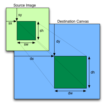
The source rectangle is the rectangle whose corners are the four points (sx, sy), (sx+sw, sy), (sx+sw, sy+sh), (sx, sy+sh).
If the source rectangle is not entirely within the source image, or if
one of the sw or sh arguments is
zero, the implementation must raise an INDEX_SIZE_ERR
exception.
The destination rectangle is the rectangle whose corners are the four points (dx, dy), (dx+dw, dy), (dx+dw, dy+dh), (dx, dy+dh).
When drawImage() is invoked, the region of the
image specified by the source rectangle must be painted on the region of
the canvas specified by the destination rectangle, after applying the current
transformation matrix to the points of the destination rectangle.
When a canvas is drawn onto itself, the drawing model requires the source to be copied before the image is drawn back onto the canvas, so it is possible to copy parts of a canvas onto overlapping parts of itself.
When the drawImage() method is passed, as its image argument, an animated image, the poster frame of the
animation, or the first frame of the animation if there is no poster
frame, must be used.
Images are painted without affecting the current path, and are subject to shadow effects, global alpha, the clipping region, and global composition operators.
The createImageData(sw, sh) method must return
an ImageData object representing a
rectangle with a width in CSS pixels equal to the absolute magnitude of
sw and a height in CSS pixels equal to the absolute
magnitude of sh, filled with transparent black.
The getImageData(sx, sy, sw, sh) method must return an ImageData object representing the underlying
pixel data for the area of the canvas denoted by the rectangle whose
corners are the four points (sx, sy), (sx+sw, sy), (sx+sw, sy+sh), (sx,
sy+sh), in canvas
coordinate space units. Pixels outside the canvas must be returned as
transparent black. Pixels must be returned as non-premultiplied alpha
values.
If any of the arguments to createImageData() or getImageData() are infinite or NaN, or if
either the sw or sh arguments are
zero, the method must instead raise an INDEX_SIZE_ERR
exception.
ImageData objects must be
initialized so that their width attribute is set to
w, the number of physical device pixels per row in the
image data, their height attribute is set to
h, the number of rows in the image data, and the data attribute is
initialized to an array of h×w×4 integers. The pixels must be represented in this
array in left-to-right order, row by row, starting at the top left, with
each pixel's red, green, blue, and alpha components being given in that
order. Each component of each device pixel represented in this array must
be in the range 0..255, representing the 8 bit value for that component.
At least one pixel must be returned.
The values of the data array may be changed (the length of the
array, and the other attributes in ImageData objects, are all read-only). On
setting, JS undefined values must be converted to zero. Other
values must first be converted to numbers using JavaScript's ToNumber
algorithm, and if the result is a NaN value, a
TYPE_MISMATCH_ERR exception must be raised. If the result is
less than 0, it must be clamped to zero. If the result is more than 255,
it must be clamped to 255. If the number is not an integer, it must be
rounded to the nearest integer using the IEEE 754r roundTiesToEven
rounding mode. [ECMA262] [IEEE754R]
The width and height (w and h) might be different from the sw and sh arguments to the above methods, e.g. if the canvas is backed by a high-resolution bitmap, or if the sw and sh arguments are negative.
The putImageData(imagedata, dx, dy,
dirtyX, dirtyY, dirtyWidth, dirtyHeight)
method writes data from ImageData
structures back to the canvas.
If the first argument to the method is null or not an ImageData object that was returned by createImageData() or getImageData() then the putImageData() method must raise a
TYPE_MISMATCH_ERR exception.
If any of the arguments to the method are infinite or NaN, the method
must raise an INDEX_SIZE_ERR exception.
When the last four arguments are omitted, they must be assumed to have
the values 0, 0, the width member of the imagedata structure, and the heightmember of
the imagedata structure, respectively.
When invoked with arguments that do not, per the last few paragraphs,
cause an exception to be raised, the putImageData() method must act as follows:
Let dxdevice be the x-coordinate of the device pixel in the underlying pixel data of the canvas corresponding to the dx coordinate in the canvas coordinate space.
Let dydevice be the y-coordinate of the device pixel in the underlying pixel data of the canvas corresponding to the dy coordinate in the canvas coordinate space.
If dirtyWidth is negative, let dirtyX be dirtyX+dirtyWidth, and let dirtyWidth be equal to the absolute magnitude of dirtyWidth.
If dirtyHeight is negative, let dirtyY be dirtyY+dirtyHeight, and let dirtyHeight be equal to the absolute magnitude of dirtyHeight.
If dirtyX is negative, let dirtyWidth be dirtyWidth+dirtyX, and let dirtyX be zero.
If dirtyY is negative, let dirtyHeight be dirtyHeight+dirtyY, and let dirtyY be zero.
If dirtyX+dirtyWidth is greater than the width attribute
of the imagedata argument, let dirtyWidth be the value of that width attribute,
minus the value of dirtyX.
If dirtyY+dirtyHeight is greater than the height
attribute of the imagedata argument, let dirtyHeight be the value of that height
attribute, minus the value of dirtyY.
If, after those changes, either dirtyWidth or dirtyHeight is negative or zero, stop these steps without affecting the canvas.
Otherwise, for all values of x and y where dirtyX ≤ x < dirtyX+dirtyWidth and dirtyY ≤ y < dirtyY+dirtyHeight, copy the four channels of the pixel with coordinate (x, y) in the imagedata data structure to the pixel with coordinate (xdevice+x, ydevice+y) in the underlying pixel data of the canvas.
The handling of pixel rounding when the specified coordinates do not exactly map to the device coordinate space is not defined by this specification, except that the following must result in no visible changes to the rendering:
context.putImageData(context.getImageData(x, y, w, h), x, y);
...for any value of x and y. In
other words, while user agents may round the arguments of the two methods
so that they map to device pixel boundaries, any rounding performed must
be performed consistently for both the getImageData() and putImageData() operations.
The current path, transformation matrix, shadow attributes, global alpha, the
clipping region, and global composition
operator must not affect the getImageData() and putImageData() methods.
The data returned by getImageData() is at the resolution of
the canvas backing store, which is likely to not be one device pixel to
each CSS pixel if the display used is a high resolution display. Thus,
while one could create an ImageData
object, one would not necessarily know what resolution the canvas
expected (how many pixels the canvas wants to paint over one coordinate
space unit pixel).
In the following example, the script first obtains the size of the
canvas backing store, and then generates a few new ImageData objects which can be used.
  // canvas is a reference to a <canvas> element
  var context = canvas.getContext('2d');

  // create a blank slate
  var data = context.createImageData(canvas.width, canvas.height);

  // create some plasma
  FillPlasma(data, 'green'); // green plasma

  // add a cloud to the plasma
  AddCloud(data, data.width/2, data.height/2); // put a cloud in the middle

  // paint the plasma+cloud on the canvas
  context.putImageData(data, 0, 0);

  // support methods
  function FillPlasma(data, color) { ... }
  function AddCloud(data, x, y) { ... }
Here is an example of using getImageData() and putImageData() to implement an edge
detection filter.
<!DOCTYPE HTML>
<html>
 <head>
  <title>Edge detection demo</title>
  <script>
   var image = new Image();
   function init() {
     image.onload = demo;
     image.src = "image.jpeg";
   }
   function demo() {
     var canvas = document.getElementsByTagName('canvas')[0];
     var context = canvas.getContext('2d');

     // draw the image onto the canvas
     context.drawImage(image, 0, 0);

     // get the image data to manipulate
     var input = context.getImageData(0, 0, canvas.width, canvas.height);

     // get an empty slate to put the data into
     var output = context.crateImageData(canvas.width, canvas.height);

     // alias some variables for convenience
     // notice that we are using input.width and input.height here
     // as they might not be the same as canvas.width and canvas.height
     // (in particular, they might be different on high-res displays)
     var w = input.width, h = input.height;
     var inputData = input.data;
     var outputData = output.data;

     // edge detection
     for (var y = 1; y < h-1; y += 1) {
       for (var x = 1; x < w-1; x += 1) {
         for (var c = 0; c < 3; c += 1) {
           var i = (y*w + x)*4 + c;
           outputData[i] = 127 + -inputData[i - w*4 - 4] -   inputData[i - w*4] - inputData[i - w*4 + 4] +
                                 -inputData[i - 4]       + 8*inputData[i]       - inputData[i + 4] +
                                 -inputData[i + w*4 - 4] -   inputData[i + w*4] - inputData[i + w*4 + 4];
         }
         outputData[(y*w + x)*4 + 3] = 255; // alpha
       }
     }

     // put the image data back after manipulation
     context.putImageData(output, 0, 0);
   }
  </script>
 </head>
 <body onload="init()">
  <canvas></canvas>
 </body>
</html>
When a shape or image is painted, user agents must follow these steps, in the order given (or act as if they do):
Render the shape or image, creating image A, as described in the previous sections. For shapes, the current fill, stroke, and line styles must be honored, and the stroke must itself also be subjected to the current transformation matrix.
If shadows are supported:
Render the shadow from image A, using the current shadow styles, creating image B.
Multiply the alpha component of every pixel in B
by globalAlpha.
Within the clipping region, composite B over the current canvas bitmap using the current composition operator.
Multiply the alpha component of every pixel in A
by globalAlpha.
Within the clipping region, composite A over the current canvas bitmap using the current composition operator.
The canvas APIs must perform color
correction at only two points: when rendering images with their own gamma
correction and color space information onto the canvas, to convert the
image to the color space used by the canvas (e.g. using the drawImage()
method with an HTMLImageElement object), and when
rendering the actual canvas bitmap to the output device.
Thus, in the 2D context, colors used to draw shapes onto the
canvas will exactly match colors obtained through the getImageData() method.
The toDataURL() method must not include color
space information in the resource returned. Where the output format allows
it, the color of pixels in resources created by toDataURL()
must match those returned by the getImageData() method.
In user agents that support CSS, the color space used by a canvas element must match the color space used
for processing any colors for that element in CSS.
The gamma correction and color space information of images must be
handled in such a way that an image rendered directly using an img element would use the same colors as one
painted on a canvas element that is
then itself rendered. Furthermore, the rendering of images that have no
color correction information (such as those returned by the toDataURL()
method) must be rendered with no color correction.
Thus, in the 2D context, calling the drawImage()
method to render the output of the toDataURL() method to the canvas, given the
appropriate dimensions, has no visible effect.
canvas elementsInformation leakage can occur if scripts from one origin are exposed to images from another origin (one that isn't the same).
To mitigate this, canvas elements are
defined to have a flag indicating whether they are origin-clean.
All canvas elements must start with
their origin-clean set to true. The flag must be set to false if
any of the following actions occur:
The element's 2D context's drawImage() method is called with an
HTMLImageElement whose origin is not the same as that of the Document object that owns
the canvas element.
The element's 2D context's drawImage() method is called with an
HTMLCanvasElement whose
origin-clean flag is false.
The element's 2D context's fillStyle attribute is set to a CanvasPattern object that was created
from an HTMLImageElement
whose origin is not the same as that of the Document object
that owns the canvas element.
The element's 2D context's fillStyle attribute is set to a CanvasPattern object that was created
from an HTMLCanvasElement
whose origin-clean flag is false.
The element's 2D context's strokeStyle attribute is set to a
CanvasPattern object that was
created from an HTMLImageElement whose origin is not the same as that of the Document object that owns
the canvas element.
The element's 2D context's strokeStyle attribute is set to a
CanvasPattern object that was
created from an HTMLCanvasElement whose
origin-clean flag is false.
Whenever the toDataURL() method of a canvas element whose origin-clean flag is
set to false is called, the method must immediately raise a security
exception.
Whenever the getImageData() method of the 2D context of
a canvas element whose
origin-clean flag is set to false is called, the method must
immediately raise a security exception.
map elementname
interface HTMLMapElement : HTMLElement {
           attribute DOMString name;
  readonly attribute HTMLCollection areas;
  readonly attribute HTMLCollection images;
};
The map element, in conjunction with any
area element descendants, defines an image map.
The name attribute
gives the map a name so that it can be referenced. The attribute must be
present and must have a non-empty value. Whitespace is significant in this
attribute's value. If the id
attribute is also specified, both attributes must have the same value.
The areas attribute
must return an HTMLCollection
rooted at the map element, whose filter
matches only area elements.
The images
attribute must return an HTMLCollection rooted at the
Document node, whose filter matches only img and object
elements that are associated with this map
element according to the image map processing model.
The DOM attribute name must reflect the content attribute of the same name.
area elementmap element ancestor.
alt
coords
shape
href
target
ping
rel
media
hreflang
type
interface HTMLAreaElement : HTMLElement {
           attribute DOMString alt;
           attribute DOMString coords;
           attribute DOMString shape;
           attribute DOMString href;
           attribute DOMString target;
           attribute DOMString ping;
           attribute DOMString rel;
  readonly attribute DOMTokenList relList;
           attribute DOMString media;
           attribute DOMString hreflang;
           attribute DOMString type;
};
The area element represents either a
hyperlink with some text and a corresponding area on an image map, or a dead area on an image map.
If the area element has an href attribute, then
the area element represents a hyperlink; the alt attribute, which must then be
present, specifies the text.
However, if the area element has no
href
attribute, then the area represented by the element cannot be selected,
and the alt attribute
must be omitted.
In both cases, the shape and coords attributes specify the area.
The shape
attribute is an enumerated attribute. The
following table lists the keywords defined for this attribute. The states
given in the first cell of the rows with keywords give the states to which
those keywords map. Some of the keywords are non-conforming, as noted in
the last column.
| State | Keywords | Notes |
|---|---|---|
| Circle state | circ
| Non-conforming |
circle
| ||
| Default state | default
| |
| Polygon state | poly
| |
polygon
| Non-conforming | |
| Rectangle state | rect
| |
rectangle
| Non-conforming |
The attribute may be omitted. The missing value default is the rectangle state.
The coords
attribute must, if specified, contain a valid list of
integers. This attribute gives the coordinates for the shape described
by the shape
attribute. The processing for this attribute is described as part of the
image map processing model.
In the circle state,
area elements must have a coords attribute
present, with three integers, the last of which must be non-negative. The
first integer must be the distance in CSS pixels from the left edge of the
image to the center of the circle, the second integer must be the distance
in CSS pixels from the top edge of the image to the center of the circle,
and the third integer must be the radius of the circle, again in CSS
pixels.
In the default
state state, area elements must not
have a coords
attribute.
In the polygon state,
area elements must have a coords attribute with
at least six integers, and the number of integers must be even. Each pair
of integers must represent a coordinate given as the distances from the
left and the top of the image in CSS pixels respectively, and all the
coordinates together must represent the points of the polygon, in order.
In the rectangle
state, area elements must have a
coords attribute
with exactly four integers, the first of which must be less than the
third, and the second of which must be less than the fourth. The four
points must represent, respectively, the distance from the left edge of
the image to the top left side of the rectangle, the distance from the top
edge to the top side, the distance from the left edge to the right side,
and the distance from the top edge to the bottom side, all in CSS pixels.
When user agents allow users to follow hyperlinks created using the area element, as described in the next section,
the href,
target and
ping attributes
decide how the link is followed. The rel, media, hreflang, and type attributes may
be used to indicate to the user the likely nature of the target resource
before the user follows the link.
The target, ping, rel, media, hreflang, and type attributes
must be omitted if the href attribute is not present.
The activation behavior of area elements is to run the following steps:
DOMActivate event in
question is not trusted (i.e. a
click() method call was
the reason for the event being dispatched), and the area element's target attribute is ... then raise an INVALID_ACCESS_ERR
exception.
area element, if any.
One way that a user agent can enable users to follow
hyperlinks is by allowing area elements
to be clicked, or focussed and activated by the keyboard. This will cause the aforementioned activation behavior to be invoked.
The DOM attributes alt, coords, href, target, ping, rel, media, hreflang, and type, each must reflect the respective content attributes of the same
name.
The DOM attribute shape must reflect the shape content attribute, limited to only known values.
The DOM attribute relList must reflect the rel content attribute.
An image map allows geometric areas on an image to be associated with hyperlinks.
An image, in the form of an img element
or an object element representing an
image, may be associated with an image map (in the form of a map element) by specifying a usemap attribute on the
img or object element. The usemap attribute, if specified, must be a valid hash-name reference to a map element.
If an img element or an object element representing an image has a usemap attribute specified, user agents must
process it as follows:
First, rules for parsing a hash-name reference
to a map element must be followed. This
will return either an element (the map) or null.
If that returned null, then abort these steps. The image is not associated with an image map after all.
Otherwise, the user agent must collect all the area elements that are descendants of the map. Let those be the areas.
Having obtained the list of area
elements that form the image map (the areas),
interactive user agents must process the list in one of two ways.
If the user agent intends to show the text that the img element represents, then it must use the
following steps.
In user agents that do not support images, or that have
images disabled, object elements cannot
represent images, and thus this section never applies (the fallback content is shown instead). The following
steps therefore only apply to img
elements.
Remove all the area elements in areas that have no href attribute.
Remove all the area elements in areas that have no alt attribute, or whose alt attribute's value is
the empty string, if there is another area element in areas with
the same value in the href attribute and with a non-empty alt attribute.
Each remaining area element in areas represents a hyperlink.
Those hyperlinks should all be made available to the user in a manner
associated with the text of the img.
In this context, user agents may represent area and img
elements with no specified alt attributes, or
whose alt attributes are the empty string or some
other non-visible text, in a user-agent-defined fashion intended to
indicate the lack of suitable author-provided text.
If the user agent intends to show the image and allow interaction with
the image to select hyperlinks, then the image must be associated with a
set of layered shapes, taken from the area elements in areas, in
reverse tree order (so the last specified area element in the map is the
bottom-most shape, and the first element in the map,
in tree order, is the top-most shape).
Each area element in areas must be processed as follows to obtain a shape to
layer onto the image:
Find the state that the element's shape attribute represents.
Use the rules for parsing a list of integers to
parse the element's coords attribute, if it is present, and let
the result be the coords list. If the attribute is
absent, let the coords list be the empty list.
If the number of items in the coords list is less
than the minimum number given for the area element's current state, as per the
following table, then the shape is empty; abort these steps.
| State | Minimum number of items |
|---|---|
| Circle state | 3 |
| Default state | 0 |
| Polygon state | 6 |
| Rectangle state | 4 |
Check for excess items in the coords list as per
the entry in the following list corresponding to the shape attribute's
state:
If the shape
attribute represents the rectangle state, and the first number in
the list is numerically less than the third number in the list, then
swap those two numbers around.
If the shape
attribute represents the rectangle state, and the second number in
the list is numerically less than the fourth number in the list, then
swap those two numbers around.
If the shape
attribute represents the circle state, and the third number in
the list is less than or equal to zero, then the shape is empty; abort
these steps.
Now, the shape represented by the element is the one described for the
entry in the list below corresponding to the state of the shape attribute:
Let x be the first number in coords, y be the second number, and r be the third number.
The shape is a circle whose center is x CSS pixels from the left edge of the image and x CSS pixels from the top edge of the image, and whose radius is r pixels.
The shape is a rectangle that exactly covers the entire image.
Let xi be the (2i)th entry in coords, and yi be the (2i+1)th entry in coords (the first entry in coords being the one with index 0).
Let the coordinates be (xi, yi), interpreted in CSS pixels measured from the top left of the image, for all integer values of i from 0 to (N/2)-1, where N is the number of items in coords.
The shape is a polygon whose vertices are given by the coordinates, and whose interior is established using the even-odd rule. [GRAPHICS]
Let x1 be the first number in coords, y1 be the second number, x2 be the third number, and y2 be the fourth number.
The shape is a rectangle whose top-left corner is given by the coordinate (x1, y1) and whose bottom right corner is given by the coordinate (x2, y2), those coordinates being interpreted as CSS pixels from the top left corner of the image.
For historical reasons, the coordinates must be interpreted relative
to the displayed image, even if it stretched using CSS or the
image element's width and height attributes.
Mouse clicks on an image associated with a set of layered shapes per the
above algorithm must be dispatched to the top-most shape covering the
point that the pointing device indicated (if any), and then, must be
dispatched again (with a new Event object) to the image
element itself. User agents may also allow individual area elements representing hyperlinks to be selected and activated (e.g. using a
keyboard); events from this are not also propagated to the image.
Because a map element (and
its area elements) can be associated with
multiple img and object elements, it is possible for an area element to correspond to multiple focusable
areas of the document.
Image maps are live; if the DOM is mutated, then the user agent must act as if it had rerun the algorithms for image maps.
The math element from the MathML
namespace falls into the embedded content
category for the purposes of the content models in this specification.
User agents must handle text other than inter-element whitespace found in MathML
elements whose content models do not allow raw text by pretending for the
purposes of MathML content models, layout, and rendering that that text is
actually wrapped in an mtext element in the MathML namespace. (Such text is not, however,
conforming.)
User agents must act as if any MathML element whose contents does not
match the element's content model was replaced, for the purposes of MathML
layout and rendering, by an merror element in the MathML namespace containing some appropriate error
message.
To enable authors to use MathML tools that only accept MathML in its XML form, interactive HTML user agents are encouraged to provide a way to export any MathML fragment as a namespace-well-formed XML fragment.
The svg element from the SVG
namespace falls into the embedded content
category for the purposes of the content models in this specification.
To enable authors to use SVG tools that only accept SVG in its XML form, interactive HTML user agents are encouraged to provide a way to export any SVG fragment as a namespace-well-formed XML fragment.
The width and
height attributes
on img, embed, object,
and video elements may be specified to
give the dimensions of the visual content of the element (the width and
height respectively, relative to the nominal direction of the output
medium), in CSS pixels. The attributes, if specified, must have values
that are valid positive non-zero integers.
The specified dimensions given may differ from the dimensions specified in the resource itself, since the resource may have a resolution that differs from the CSS pixel resolution. (On screens, CSS pixels have a resolution of 96ppi, but in general the CSS pixel resolution depends on the reading distance.) If both attributes are specified, then the ratio of the specified width to the specified height must be the same as the ratio of the logical width to the logical height in the resource. The two attributes must be omitted if the resource in question does not have both a logical width and a logical height.
To parse the attributes, user agents must use the rules for parsing dimension values. This will return either an integer length, a percentage value, or nothing. The user agent requirements for processing the values obtained from parsing these attributes are described in the rendering section. If one of these attributes, when parsing, returns no value, it must be treated, for the purposes of those requirements, as if it was not specified.
The width and height DOM attributes
on the embed, object, and video elements must reflect the content attributes of the same name.