Abstract
SVG is language for describing vector graphics, however it's typically rendered on raster displays. SVG filter effects is a way of processing the generated raster image before it's displayed.
Although originally designed for use in SVG, filter effects are defined in XML and are accessed via a presentation property, and therefore could be used in other environments, such as HTML styled with CSS and XSL:FO.
This document defines the markup used by SVG filters.
Status of This Document
This section describes the status of this document at the time of its publication. Other documents may supersede this document. A list of current W3C publications and the latest revision of this technical report can be found in the W3C technical reports index at http://www.w3.org/TR/.
This document is the First Public Working Draft of this specification.
There is an accompanying SVG Filters 1.2, Part
1: Primer that lists the ways SVG filters may be used.
This document has been produced by the W3C SVG Working Group as
part of the W3C Graphics Activity within the
Interaction Domain. The Working Group expects to advance this Working Draft to Recommendation Status.
We explicitly invite comments on this specification. Please send them to www-svg@w3.org: the public email list for
issues related to vector graphics on the Web (archives). Acceptance
of the archiving policy is requested automatically upon first post to the
list. To subscribe send an email to
www-svg-request@w3.org with
the word subscribe in the subject line.
This document was produced by a group operating under the
5
February 2004 W3C Patent Policy.
W3C maintains a public list of any
patent disclosures made in connection with the
deliverables of the group; that page also includes
instructions for disclosing a patent.
An individual who has actual knowledge of a patent which the
individual believes contains Essential Claim(s) must disclose the
information in accordance with section 6 of the W3C Patent Policy.
Publication as a Working Draft does not imply endorsement by the W3C Membership.
This is a draft document and may be updated, replaced or obsoleted by other
documents at any time. It is inappropriate to cite this document as other than
work in progress.
How to read this document and give feedback
This draft of SVG Filters is essentially the filter chapter from SVG 1.1. One of the goals is that this specification
can be re-used more easily by other specifications that want to have filter
effects. Some things that have been changed are: error handling is more
similar to SVG Tiny 1.2, the addition of a 'feDropShadow' filter primitive and the
possibility to filter bitmap data with the DOM.
Sections have been marked with green sidebars if it's new since SVG 1.1, and in blue if it's been changed since SVG 1.1.
The main purpose of this document is to encourage public feedback. The
best way to give feedback is by sending an email to public-svg-filters@w3.org. Please
include some kind of keyword that identifies the area of the specification
the comment is referring to in the subject line of your message (e.g "Section
X.Y - the 'filter' property" or "Filtering primitive handling"). If you have
comments on multiple areas of this document, then it is probably best to
split those comments into multiple messages.
The public are welcome to comment on any aspect in this document, but
there are a few areas in which the SVG Working Group are explicitly
requesting feedback. These areas are noted in place within this document.
There is also a specific area related to the specification that is listed
here:
Table of Contents
1 Introduction
This chapter describes a declarative filter effects feature set, which
when combined with the other web technologies, like SVG or HTML, can describe
much of the common artwork on the Web in such a way that client-side
generation and alteration can be performed easily. In addition, the ability
to apply filter effects to SVG graphics elements and container elements helps to
maintain the semantic structure of the document, instead of resorting to
images which aside from generally being a fixed resolution tend to obscure
the original semantics of the elements they replace. This is especially true
for effects applied to text. The various usage scenarios are listed in the
SVG Filters Requirements document.
Note that even though this specification references parts of SVG 1.1 it does not require a complete SVG 1.1
implementation.
This document is normative.
This document contains explicit conformance criteria that overlap with
some RNG definitions in requirements. If there is any conflict between the
two, the explicit conformance criteria are the definitive reference.
A filter effect consists of a series of graphics operations that are
applied to a given source graphic to produce a modified graphical
result. The result of the filter effect is rendered to the target device
instead of the original source graphic. The following illustrates the
process:
2 The 'filter'
element
The description of the 'filter' element
follows:
Attribute definitions:
- filterUnits = "userSpaceOnUse |
objectBoundingBox"
- See Filter effects region.
- primitiveUnits = "userSpaceOnUse |
objectBoundingBox"
- Specifies the coordinate system for the various length values within
the filter primitives and for the attributes that define the filter primitive subregion.
If primitiveUnits="userSpaceOnUse", any length values
within the filter definitions represent values in the current user
coordinate system in place at the time when the 'filter'
element is referenced (i.e., the user coordinate system for the element
referencing the 'filter' element via a 'filter'
property).
If primitiveUnits="objectBoundingBox", then any length
values within the filter definitions represent fractions or percentages
of the bounding box on the referencing element (see Object bounding box
units
).
If attribute primitiveUnits is not
specified, then the effect is as if a value of userSpaceOnUse were specified.
Animatable:yes.
- filterMarginUnits = "userSpaceOnUse |
objectBoundingBox"
- See Filter effects region.
- primitiveMarginUnits = "userSpaceOnUse |
objectBoundingBox"
- Specifies the coordinate system for the margin attributes within the
filter primitives which is used for determining the filter primitive subregion.
If primitiveMarginUnits="userSpaceOnUse", any margin
attribute values within the filter definitions represent values in the
current user coordinate system in place at the time when the 'filter'
element is referenced (i.e., the user coordinate system for the element
referencing the 'filter' element via a 'filter'
property).
If primitiveMarginUnits="objectBoundingBox", then any
margin attribute values within the filter definitions represent
fractions or percentages of the bounding box on the referencing element
(see Object bounding box units
).
If attribute primitiveMarginUnits is
not specified, then the effect is as if a value of userSpaceOnUse were specified.
Animatable:yes.
-
x = "<coordinate>"
- See Filter effects region.
-
y = "<coordinate>"
- See Filter effects region.
- width =
"<length>"
- See Filter effects region.
- height =
"<length>"
- See Filter effects region.
-
mx = "<coordinate>"
- The margin delta for the x coordinate of the subregion which
restricts calculation and rendering of the given filter primitive. If
this attribute is not specified, the effect is as if a value of 0 were specified. See filter primitive subregion.
Animatable:yes.
-
my = "<coordinate>"
- The margin delta for the y coordinate of the subregion which
restricts calculation and rendering of the given filter primitive. If
this attribute is not specified, the effect is as if a value of 0 were specified. See filter primitive subregion.
Animatable:yes.
-
mw = "<length>"
- The margin delta for the width of the subregion which restricts
calculation and rendering of the given filter primitive. If this
attribute is not specified, the effect is as if a value of 0 were specified. See filter primitive subregion.
Animatable:yes.
-
mh = "<length>"
- The margin delta for the height of the subregion which restricts
calculation and rendering of the given filter primitive. If this
attribute is not specified, the effect is as if a value of 0 were specified. See filter primitive subregion.
Animatable:yes.
- filterRes = "<number-optional-number>"
- See Filter effects region.
-
xlink:href
= "<XMLRI>"
A URI reference
to another 'filter' element within
the current SVG document fragment. Any attributes which are defined on
the referenced 'filter' element which
are not defined on this element are inherited by this element. If this
element has no defined filter nodes, and the referenced element has
defined filter nodes (possibly due to its own href attribute), then this element inherits
the filter nodes defined from the referenced 'filter' element. Inheritance can be
indirect to an arbitrary level; thus, if the referenced 'filter' element inherits attributes or its
filter node specification due to its own href attribute, then the current element can
inherit those attributes or filter node specifications.
This attribute is deprecated and should not be used, it's included for
backwards compatibility reasons only.
Animatable:yes.
Properties inherit into the 'filter'
element from its ancestors; properties do not inherit from the
element referencing the 'filter'
element.
'filter' elements are never rendered
directly; their only usage is as something that can be referenced using the
'filter'
property. The 'display' property does not
apply to the 'filter' element; thus, 'filter' elements are not directly rendered even
if the 'display' property is set to a value
other than none, and 'filter' elements are available for referencing
even when the 'display' property on the 'filter' element or any of its ancestors is set
to none.
3 The 'filter'
property
The description of the 'filter' property is
as follows:
- 'filter'
-
| Value: |
<FuncXMLRI> | none | inherit |
| Initial: |
none |
| Applies to: |
All elements that render. The host language is resposible for
stating which elements render.
For svg: container elements
and graphics elements
. |
| Inherited: |
no |
| Percentages: |
N/A |
| Media: |
visual |
| Animatable: |
yes |
- <FuncXMLRI>
- An IRI reference
to a 'filter' element which defines the
filter effects that shall be applied to this element.
- none
- Do not apply any filter effects to this element.
4 Filter effects region
A 'filter'
element can define a region on the canvas to which a given filter effect
applies and can provide a resolution for any intermediate continuous tone
images used to process any raster-based filter primitives.
4.1 Filter Region extensions
In SVG 1.1, a filter
defines the area upon which it applies. This makes it difficult to develop a
generic filter that can be applied to arbitrary graphics, since the filter
must define a large enough area to cover any graphical object to which it is
applied. An example of this is a generic "drop shadow" filter, which is
commonly specified as a combination of a Gaussian blur feGuassianBlur) that is offset feOffset) and then composed feComposite) with the original source graphic.
Since the shadow has to extend beyond the original graphic's boundaries, the
filter must be defined to have a larger area than the original graphic.
Overestimating this margin has a negative effect on performance, since the
complex filter operation has to touch a larger amount of user space (ie.
pixels).
In order to solve this problem this spec allows additional control over
the filter region. The outer filter region is expressed by delta to the
x,
y,
width,
height
of the input filter region.
In particular, the filterMarginUnits, primitiveMarginUnits, mx, my, mw and mh are
added to the 'filter' element. The filterMarginUnits specifies the coordinate space of
the new margin attributes, which are used to increase or decrease the 'filter' element's
x,
y,
width and
height
attributes (once they have been calculated). The primitiveMarginUnits specifies the units for the
new margin attributes on the filter primitives, also named
mx,
my,
mw,
mh.
These margins attribute override those set on the parent filter element. Note that this doesn't mean that a
filter primitive can expand the filter region itself, just that the
coordinate system used for filter primitives margin attributes can be
different than the one used for the margin attributes on the
'filter' element.
An example of the new attributes, which defines a generic drop shadow
filter:
	<filter id="dropShadow" x="0" y="0" width="1" height="1"
			  filterMarginUnits="userSpaceOnUse"
			  mx="0" my="0" mw="5" mh="5" >
		  <feGaussianBlur stdDeviation="2" in="SourceAlpha" />
		  <feOffset dx="2" />
		  <feMerge>
			   <feMergeNode />
			   <feMergeNode in="SourceGraphic" />
		  </feMerge>
	</filter>
In the above example, the filter region by default covers the entire
bounds of the object (which is not enough to show the shadow). Adding the new
margins extends the width and height by 5 user units each, which is always
enough to display the blur (which has a standard deviation of 2 user units)
and offset (which is another 2 units).
The 'filter'
element has the following attributes which work together to define the filter
effects region:
-
filterUnits={ userSpaceOnUse | objectBoundingBox }.
Defines the coordinate system for attributes x, y,
width, height.
If filterUnits="userSpaceOnUse", x, y,
width, height represent values in the current user coordinate
system in place at the time when the 'filter' element is referenced (i.e., the
user coordinate system for the element referencing the 'filter'
element via a 'filter' property).
If filterUnits="objectBoundingBox", then x, y,
width, height represent fractions or percentages of the
bounding box on the referencing element (see Object bounding box units
).
If attribute filterUnits is not specified,
then the effect is as if a value of objectBoundingBox were specified.
Animatable:yes.
- x, y, width,
height, which define a rectangular region on the canvas to which
this filter applies.
The amount of memory and processing time required to apply the filter are
related to the size of this rectangle and the filterRes attribute of the filter.
The coordinate system for these attributes depends on the value for
attribute filterUnits.
The bounds of this rectangle act as a hard clipping region for each filter primitive included with a
given 'filter' element; thus, if the effect of
a given filter primitive would extend beyond the bounds of the rectangle
(this sometimes happens when using a 'feGaussianBlur' filter primitive with a
very large stdDeviation), parts of the effect will get
clipped.
If x or y is not specified, the effect
is as if a value of "-10%" were specified.
If width or height is not specified,
the effect is as if a value of "120%" were specified.
Negative or zero values for width or
height disable rendering of the element which referenced
the filter.
Animatable:yes.
-
filterMarginUnits={ userSpaceOnUse | objectBoundingBox
}.
Defines the coordinate system for attributes mx, my,
mw, mh.
If filterMarginUnits="userSpaceOnUse", mx, my,
mw, mh represent values in the current user coordinate system
in place at the time when the 'filter' element is referenced (i.e., the
user coordinate system for the element referencing the 'filter'
element via a 'filter' property).
If filterMarginUnits="objectBoundingBox", then mx, my,
mw, mh represent fractions or percentages of the bounding box
on the referencing element (see Object bounding box units
).
If attribute filterMarginUnits is not
specified, then the effect is as if a value of userSpaceOnUse were specified.
Animatable:yes.
- mx, my, mw, mh,
which define deltas to the x, y, width, height of the filter region.
After the x, y, width, height have been calculated for the filter region the
mx, my, mw, mh are calculated and added to the filter region. If the
resulting filter region has a negative or zero width or height, the
rendering of the element which referenced the filter is disabled.
The coordinate system for these attributes depends on the value for
attribute filterMarginUnits.
If mx or my is not specified, the
effect is as if a value of 0 were
specified.
If mw or mh is not specified, the
effect is as if a value of 0 were
specified.
Animatable:yes.
- filterRes (which has the form
x-pixels
    [y-pixels])
indicates the width and height of the intermediate
images in pixels. If not provided, then a reasonable default resolution
appropriate for the target device will be used. (For displays, an
appropriate display resolution, preferably the current display's pixel
resolution, is the default. For printing, an appropriate common printer
resolution, such as 400dpi, is the default.)
Care should be taken when assigning a non-default value to this
attribute. Too small of a value may result in unwanted pixelation in the
result. Too large of a value may result in slow processing and large
memory usage.
Negative or zero values disable rendering of the element which referenced
the filter.
Animatable:yes.
Note that both of the two possible value for filterUnits (i.e., objectBoundingBox and userSpaceOnUse) result in a filter region whose
coordinate system has its X-axis and Y-axis each parallel to the X-axis and
Y-axis, respectively, of the user coordinate system for the element to which
the filter will be applied.
Sometimes implementers can achieve faster performance when the filter
region can be mapped directly to device pixels; thus, for best performance on
display devices, it is suggested that authors define their region such that
the user agent can align the filter region pixel-for-pixel with the
background. In particular, for best filter effects performance, avoid
rotating or skewing the user coordinate system. Explicit values for attribute
filterRes can either help or harm performance.
If filterRes is smaller than the automatic
(i.e., default) filter resolution, then filter effect might have faster
performance (usually at the expense of quality). If filterRes is larger than the automatic (i.e.,
default) filter resolution, then filter effects performance will usually be
slower.
It is often necessary to provide padding space because the filter effect
might impact bits slightly outside the tight-fitting bounding box on a given
object. For these purposes, it is possible to provide negative percentage
values for x, y and percentages values greater than 100% for
width, height. This, for example, is why the defaults for
the filter effects region are x="-10%" y="-10%" width="120%"
height="120%".
5 Accessing the background image
Two possible pseudo input images for filter effects are BackgroundImage and BackgroundAlpha, which each represent an image
snapshot of the canvas under the filter region at the time that the 'filter' element
is invoked. BackgroundImage represents both
the color values and alpha channel of the canvas (i.e., RGBA pixel values),
whereas BackgroundAlpha represents only the
alpha channel.
Implementations
will often need to maintain supplemental background image buffers in order to
support the BackgroundImage and BackgroundAlpha pseudo input images. Sometimes,
the background image buffers will contain an in-memory copy of the
accumulated painting operations on the current canvas.
Because in-memory image buffers can take up significant system resources,
content must explicitly indicate to the
user agent that the document needs access to the background image before BackgroundImage and BackgroundAlpha pseudo input images can be used.
A background image is what's been rendered before the current element.
The host language is responsible for defining what rendered before in
this context means
. For SVG, that uses the painter's algorithm, rendered before means
all of the prior elements in pre order traversal previous to the element to
which the filter is applied.
The property which enables access to the background image is
'enable-background':
- 'enable-background'
-
| Value: |
accumulate | new [ <x> <y> <width>
<height> ] | inherit |
| Initial: |
accumulate |
| Applies to: |
Typically elements that can contain renderable elements. Host
language is responsible for defining the applicable set of
elements.
For SVG: container elements |
| Inherited: |
no |
| Percentages: |
N/A |
| Media: |
visual |
| Animatable: |
no |
A value of new indicates two things:
- It enables the ability of children of the current
element to access the background image.
- It indicates that a new (i.e., initially transparent black) background
image canvas is established and that (in effect) all children of the
current
element shall be rendered into the new background image canvas in
addition to being rendered onto the target device.
A meaning of enable-background: accumulate (the
initial/default value) depends on context:
- If an ancestor
element has a property value of 'enable-background:new', then all
renderable child elements of the current
element are rendered both onto the parent
element's background image canvas and onto the target device.
- Otherwise, there is no current background image canvas, so it is only
necessary to render
the renderable elements onto the target device. (No need to render to the
background image canvas.)
If a filter effect specifies either the BackgroundImage or the BackgroundAlpha pseudo input images and no
ancestor
element has a property value of 'enable-background:new', then the background
image request is technically in error. Processing will proceed without
interruption (i.e., no error message) and a transparent black image shall be
provided in response to the request.
The optional
<x>,<y>,<width>,<height> parameters
on the new value indicate the subregion of the
element to which enable-background applies' user space where access to the
background image is allowed to happen. These parameters enable the user
agent potentially to allocate smaller temporary image buffers than the
default values, which might require the user agent to allocate buffers as
large as the current viewport. Thus, the values
<x>,<y>,<width>,<height> act as a clipping rectangle
on the background image canvas. If more than zero but less than four of the
values <x>,<y>,<width> and <height> are specified or
if negative or zero values are specified for <width> or <height>,
BackgroundImage and BackgroundAlpha are processed as if background
image processing were not enabled.
5.1 Accessing the background image in SVG
This section only applies to the SVG definition of enable-background.
Assume you have an element E in the document and that E has a series of
ancestors A1 (its immediate parent), A2, etc. (Note:
A0 is E.) Each ancestor Ai will have a corresponding
temporary background image offscreen buffer BUFi. The contents of
the background image available to a 'filter' referenced by E is defined as
follows:
- Find the element Ai with the smallest subscript i (including
A0=E) for which the 'enable-background' property has the value
new. (Note: if there is no such ancestor
element, then there is no background image available to E, in which case
a transparent black image will be used as E's background image.)
- For each Ai (from i=n to 1), initialize BUFi to
transparent black. Render all children of Ai up to but not
including Ai-1 into BUFi. The children are painted,
then filtered, clipped, masked and composited using the various painting,
filtering, clipping, masking and object opacity settings on the given
child. Any filter effects, masking and group opacity that might be set on
Ai do not apply when rendering the children of
Ai into BUFi.
(Note that for the case of A0=E, the graphical contents of E
are not rendered into BUF1 and thus are not part of the
background image available to E. Instead, the graphical contents of E are
available via the SourceGraphic and SourceAlpha pseudo input images.)
- Then, for each Ai (from i=1 to n-1), composite
BUFi into BUFi+1.
- The accumulated result (i.e., BUFn) represents the
background image available to E.
<?xml version="1.0" standalone="no"?>
<!DOCTYPE svg PUBLIC "-//W3C//DTD SVG 1.1//EN"
  "http://www.w3.org/Graphics/SVG/1.1/DTD/svg11.dtd">
<svg width="13.5cm" height="2.7cm" viewBox="0 0 1350 270"
     xmlns="http://www.w3.org/2000/svg" version="1.1">
  <title>Example enable-background01</title>
  <desc>This test case shows five pictures which illustrate the rules
        for background image processing.</desc>

  <defs>
    <filter id="ShiftBGAndBlur"
            filterUnits="userSpaceOnUse" x="0" y="0" width="1200" height="400">
      <desc>
        This filter discards the SourceGraphic, if any, and just produces
        a result consisting of the BackgroundImage shifted down 125 units
        and then blurred.
      </desc>
      <feOffset in="BackgroundImage" dx="0" dy="125" />
      <feGaussianBlur stdDeviation="8" />
    </filter>
    <filter id="ShiftBGAndBlur_WithSourceGraphic"
            filterUnits="userSpaceOnUse" x="0" y="0" width="1200" height="400">
      <desc>
        This filter takes the BackgroundImage, shifts it down 125 units, blurs it,
        and then renders the SourceGraphic on top of the shifted/blurred background.
      </desc>
      <feOffset in="BackgroundImage" dx="0" dy="125" />
      <feGaussianBlur stdDeviation="8" result="blur" />
      <feMerge>
        <feMergeNode in="blur"/>
        <feMergeNode in="SourceGraphic"/>
      </feMerge>
    </filter>
  </defs>

  <g transform="translate(0,0)">
    <desc>The first picture is our reference graphic without filters.</desc>
    <rect x="25" y="25" width="100" height="100" fill="red"/>
    <g opacity=".5">
      <circle cx="125" cy="75" r="45" fill="green"/>
      <polygon points="160,25 160,125 240,75" fill="blue"/>
    </g>
    <rect x="5" y="5" width="260" height="260" fill="none" stroke="blue"/>
  </g>

  <g enable-background="new" transform="translate(270,0)">
    <desc>The second adds an empty 'g' element which invokes ShiftBGAndBlur.</desc>
    <rect x="25" y="25" width="100" height="100" fill="red"/>
    <g opacity=".5">
      <circle cx="125" cy="75" r="45" fill="green"/>
      <polygon points="160,25 160,125 240,75" fill="blue"/>
    </g>
    <g filter="url(#ShiftBGAndBlur)"/>
    <rect x="5" y="5" width="260" height="260" fill="none" stroke="blue"/>
  </g>

  <g enable-background="new" transform="translate(540,0)">
    <desc>The third invokes ShiftBGAndBlur on the inner group.</desc>
    <rect x="25" y="25" width="100" height="100" fill="red"/>
    <g filter="url(#ShiftBGAndBlur)" opacity=".5">
      <circle cx="125" cy="75" r="45" fill="green"/>
      <polygon points="160,25 160,125 240,75" fill="blue"/>
    </g>
    <rect x="5" y="5" width="260" height="260" fill="none" stroke="blue"/>
  </g>

  <g enable-background="new" transform="translate(810,0)">
    <desc>The fourth invokes ShiftBGAndBlur on the triangle.</desc>
    <rect x="25" y="25" width="100" height="100" fill="red"/>
    <g opacity=".5">
      <circle cx="125" cy="75" r="45" fill="green"/>
      <polygon points="160,25 160,125 240,75" fill="blue"
               filter="url(#ShiftBGAndBlur)"/>
    </g>
    <rect x="5" y="5" width="260" height="260" fill="none" stroke="blue"/>
  </g>

  <g enable-background="new" transform="translate(1080,0)">
    <desc>The fifth invokes ShiftBGAndBlur_WithSourceGraphic on the triangle.</desc>
    <rect x="25" y="25" width="100" height="100" fill="red"/>
    <g opacity=".5">
      <circle cx="125" cy="75" r="45" fill="green"/>
      <polygon points="160,25 160,125 240,75" fill="blue"
               filter="url(#ShiftBGAndBlur_WithSourceGraphic)"/>
    </g>
    <rect x="5" y="5" width="260" height="260" fill="none" stroke="blue"/>
  </g>
</svg>
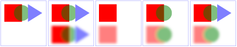
The example above contains five parts, described as follows:
- The first set is the reference graphic. The reference graphic consists
of a red rectangle followed by a 50% transparent 'g'
element. Inside the 'g'
is a green circle that partially overlaps the rectangle and a a blue
triangle that partially overlaps the circle. The three objects are then
outlined by a rectangle stroked with a thin blue line. No filters are
applied to the reference graphic.
- The second set enables background image processing and adds an empty
'g'
element which invokes the ShiftBGAndBlur filter. This filter takes the
current accumulated background image (i.e., the entire reference graphic)
as input, shifts its offscreen down, blurs it, and then writes the result
to the canvas. Note that the offscreen for the filter is initialized to
transparent black, which allows the already rendered rectangle, circle
and triangle to show through after the filter renders its own result to
the canvas.
- The third set enables background image processing and instead invokes
the ShiftBGAndBlur filter on the inner 'g'
element. The accumulated background at the time the filter is applied
contains only the red rectangle. Because the children of the inner 'g'
(i.e., the circle and triangle) are not part of the inner 'g'
element's background and because ShiftBGAndBlur ignores SourceGraphic,
the children of the inner 'g'
do not appear in the result.
- The fourth set enables background image processing and invokes the
ShiftBGAndBlur on the 'polygon'
element that draws the triangle. The accumulated background at the time
the filter is applied contains the red rectangle plus the green circle
ignoring the effect of the 'opacity'
property on the inner 'g'
element. (Note that the blurred green circle at the bottom does not let
the red rectangle show through on its left side. This is due to ignoring
the effect of the 'opacity'
property.) Because the triangle itself is not part of the accumulated
background and because ShiftBGAndBlur ignores SourceGraphic, the triangle
does not appear in the result.
- The fifth set is the same as the fourth except that filter
ShiftBGAndBlur_WithSourceGraphic is invoked instead of ShiftBGAndBlur.
ShiftBGAndBlur_WithSourceGraphic performs the same effect as
ShiftBGAndBlur, but then renders the SourceGraphic on top of the shifted,
blurred background image. In this case, SourceGraphic is the blue
triangle; thus, the result is the same as in the fourth case except that
the blue triangle now appears.
6 Filter primitives overview
6.1 Overview
This section describes the various filter primtives that can be assembled
to achieve a particular filter effect.
Unless otherwise stated, all image filters operate on premultiplied RGBA
samples. Filters which work more naturally on non-premultiplied data
(feColorMatrix and feComponentTransfer) will temporarily undo and redo
premultiplication as specified. All raster effect filtering operations take 1
to N input RGBA images, additional attributes as parameters, and produce a
single output RGBA image.
The RGBA result from each filter primitive will be clamped into the
allowable ranges for colors and opacity values. Thus, for example, the result
from a given filter primitive will have any negative color values or opacity
values adjusted up to color/opacity of zero.
The color space in which a particular filter primitive performs its
operations is determined by the value of property 'color-interpolation-filters' on the given filter
primitive. A different property, 'color-interpolation' determines the color space for
other color operations. Because these two properties have different initial
values ('color-interpolation-filters' has an
initial value of linearRGB whereas 'color-interpolation' has an initial value of sRGB), in some cases to achieve certain results
(e.g., when coordinating gradient interpolation with a filtering operation)
it will be necessary to explicitly set 'color-interpolation' to linearRGB or 'color-interpolation-filters' to sRGB on particular elements. Note that the examples
below do not explicitly set either 'color-interpolation' or 'color-interpolation-filters', so the initial values
for these properties apply to the examples.
6.2 Common attributes
The following attributes are available for most of the filter
primitives:
Attribute definitions:
-
x = "<coordinate>"
- The minimum x coordinate for the subregion which restricts
calculation and rendering of the given filter primitive. See filter primitive subregion.
Animatable:yes.
-
y = "<coordinate>"
- The minimum y coordinate for the subregion which restricts
calculation and rendering of the given filter primitive. See filter primitive subregion.
Animatable:yes.
-
width = "<length>"
- The width of the subregion which restricts calculation and rendering
of the given filter primitive. See filter primitive subregion.
A negative or zero value disables the effect of the given filter
primitive (i.e., the result is a transparent black image).
Animatable:yes.
-
height = "<length>"
- The height of the subregion which restricts calculation and rendering
of the given filter primitive. See filter primitive subregion.
A negative or zero value disables the effect of the given filter
primitive (i.e., the result is a transparent black image).
Animatable:yes.
-
mx = "<coordinate>"
- The margin delta for the x coordinate of the subregion which
restricts calculation and rendering of the given filter primitive. If
this attribute is not specified, the effect is as if a value of 0 were specified. See filter primitive subregion.
Animatable:yes.
-
my = "<coordinate>"
- The margin delta for the y coordinate of the subregion which
restricts calculation and rendering of the given filter primitive. If
this attribute is not specified, the effect is as if a value of 0 were specified. See filter primitive subregion.
Animatable:yes.
-
mw = "<length>"
- The margin delta for the width of the subregion which restricts
calculation and rendering of the given filter primitive. If this
attribute is not specified, the effect is as if a value of 0 were specified. See filter primitive subregion.
Animatable:yes.
-
mh = "<length>"
- The margin delta for the height of the subregion which restricts
calculation and rendering of the given filter primitive. If this
attribute is not specified, the effect is as if a value of 0 were specified. See filter primitive subregion.
Animatable:yes.
-
result =
"<filter-primitive-reference>"
- Assigned name for this filter primitive. If supplied, then graphics
that result from processing this filter primitive can be referenced by
an in attribute on a subsequent filter
primitive within the same 'filter' element. If no value is
provided, the output will only be available for re-use as the implicit
input into the next filter primitive if that filter primitive provides
no value for its in attribute.
Note that a <filter-primitive-reference> is not an XML
ID; instead, a <filter-primitive-reference> is only
meaningful within a given 'filter' element and thus have only
local scope. It is legal for the same
<filter-primitive-reference> to appear multiple times
within the same 'filter' element. When referenced, the
<filter-primitive-reference> will use the closest
preceding filter primitive with the given result.
Animatable:yes.
-
in = "SourceGraphic | SourceAlpha | BackgroundImage | BackgroundAlpha | FillPaint | StrokePaint |
<filter-primitive-reference>"
- Identifies input for the given filter primitive. The value can be
either one of six keywords or can be a string which matches a previous
result attribute value within the same 'filter'
element. If no value is provided and this is the first filter
primitive, then this filter primitive will use SourceGraphic
as its input. If no value is provided and this is a subsequent filter
primitive, then this filter primitive will use the result from the
previous filter primitive as its input.
If the value for result appears
multiple times within a given 'filter' element, then a reference to
that result will use the closest preceding filter primitive with the
given value for attribute result.
Forward references to results are not allowed, and will be treated as
if no result was specified.
Definitions for the six keywords:
- SourceGraphic
- This keyword represents the graphics elements
that were the original input into the 'filter' element. For raster
effects filter primitives, the graphics elements
will be rasterized into an initially clear RGBA raster in image
space. Pixels left untouched by the original graphic will be left
clear. The image is specified to be rendered in linear RGBA
pixels. The alpha channel of this image captures any
anti-aliasing specified by SVG. (Since the raster is linear, the
alpha channel of this image will represent the exact percent
coverage of each pixel.)
- SourceAlpha
- This keyword represents the graphics elements
that were the original input into the 'filter' element. SourceAlpha has all of the same rules
as SourceGraphic except that only the
alpha channel is used. The input image is an RGBA image
consisting of implicitly black color values for the RGB channels,
but whose alpha channel is the same as SourceGraphic. If this option is
used, then some implementations might need to rasterize the
graphics elements
in order to extract the alpha channel.
- BackgroundImage
- This keyword represents an image snapshot of the canvas under
the filter region at the time that the 'filter' element was invoked. See
Accessing the background
image.
- BackgroundAlpha
- Same as BackgroundImage except
only the alpha channel is used. See SourceAlpha and Accessing the background
image.
- FillPaint
-
This keyword represents the target element rendered filled. The host language is responsible for specifying what rendered filled in this context means, if not specified FillPaint will be taken to mean a transparent black image. For svg this keyword represents the value of the 'fill'
property on the target element for the filter effect.
Note that text is generally painted filled, not stroked.
The FillPaint image has conceptually infinite extent.
Frequently this image is opaque everywhere, but it
might not be if the "paint"
itself has alpha, as in the case of a gradient or pattern which
itself includes transparent or semi-transparent parts.
- StrokePaint
-
This keyword represents the target element rendered stroked. The host language is responsible for specifying what rendered stroked in this context means, if not specified StrokePaint will be taken to mean a transparent black image. For svg this keyword represents the value of the 'stroke'
property on the target element for the filter effect.
Note that text is generally painted filled, not stroked.
The StrokePaint image has conceptually infinite extent.
Frequently this image is opaque everywhere, but it
might not be if the "paint"
itself has alpha, as in the case of a gradient or pattern which
itself includes transparent or semi-transparent parts.
Animatable:yes.
6.3 Filter primitive subregion
All filter primitives have attributes x, y,
width and height, and mx,
my, mw and mh, which
together identify a subregion which restricts calculation and rendering of
the given filter primitive. The x, y,
width and height attributes are defined
according to the same rules as other filter primitives' coordinate and length
attributes and thus represent values in the coordinate system established by
attribute primitiveUnits on the 'filter' element.
The mx, my, mw and
mh attributes contain deltas to the corresponding
x, y, width and
height attributes and contain values in the coordinate
system established by attribute primitiveMarginUnits on the 'filter' element.
x, y, width and
height default to the union (i.e., tightest fitting bounding
box) of the subregions defined for all referenced nodes. If there are no
referenced nodes (e.g., for 'feImage' or 'feTurbulence'), or one or more of the
referenced nodes is a standard input (one of SourceGraphic, SourceAlpha, BackgroundImage, BackgroundAlpha,
FillPaint or StrokePaint), or for
'feTile'
(which is special because its principal function is to replicate the
referenced node in X and Y and thereby produce a usually larger result), the
default subregion is 0%,0%,100%,100%, where percentages are relative to the
dimensions of the filter region.
After the x, y, width,
height have been calculated for the filter primitive
subregion the margin attributes mx, my,
mw, mh are calculated and added to the
former to make the filter primitive subregion. If the filter primitive
subregion has a negative or zero width or height, the effect of the filter
primitive is disabled.
The filter primitive subregion act as a hard clip clipping rectangle for
the filter primitive.
All intermediate offscreens are defined to not exceed the intersection of
the filter primitive subregion with the filter
region. The filter region and any of the filter primitive subregions are
to be set up such that all offscreens are made big enough to accommodate any
pixels which even partly intersect with either the filter region or the
filter primitive subregions.
'feTile'
references a previous filter primitive and then stitches the tiles together
based on the filter primitive subregion of the referenced filter primitive in
order to fill its own filter primitive
subregion.
<svg width="400" height="400" xmlns="http://www.w3.org/2000/svg">
	<defs>
		<filter id="flood" x="0" y="0" width="100%" height="100%" primitiveUnits="objectBoundingBox">
		   <feFlood x="25%" y="25%" width="50%" height="50%"
					flood-color="green" flood-opacity="0.75"/>
		</filter>
		<filter id="blend" primitiveUnits="objectBoundingBox">
		   <feBlend x="25%" y="25%" width="50%" height="50%"
					in2="SourceGraphic" mode="multiply"/>
		</filter>
		<filter id="merge" primitiveUnits="objectBoundingBox">
		   <feMerge x="25%" y="25%" width="50%" height="50%">
				<feMergeNode in="SourceGraphic"/>
				<feMergeNode in="FillPaint"/>
		   </feMerge>
		</filter>
	</defs>

	<g fill="none" stroke="blue" stroke-width="4">
	   <rect width="200" height="200"/>
	   <line x2="200" y2="200"/>
	   <line x1="200" y2="200"/>
	</g>
	<circle fill="green" filter="url(#flood)" cx="100" cy="100" r="90"/>

	<g transform="translate(200 0)">
		<g fill="none" stroke="blue" stroke-width="4">
		   <rect width="200" height="200"/>
		   <line x2="200" y2="200"/>
		   <line x1="200" y2="200"/>
		</g>
		<circle fill="green" filter="url(#blend)" cx="100" cy="100" r="90"/>
	</g>

	<g transform="translate(0 200)">
		<g fill="none" stroke="blue" stroke-width="4">
		   <rect width="200" height="200"/>
		   <line x2="200" y2="200"/>
		   <line x1="200" y2="200"/>
		</g>
		<circle fill="green" fill-opacity="0.5" filter="url(#merge)" cx="100" cy="100" r="90"/>
	</g>
</svg>
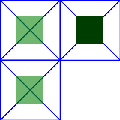
In the example above there are three rects that each have a cross and a circle in them. The circle element in each one has a different filter applied, but with the same filter primitive subregion. The filter output should be limited to the filter primitive subregion, so you should never see the circles themselves, just the rects that make up the filter primitive subregion.
-
The upper left rect shows an 'feFlood' with flood-opacity="75%" so the cross should be visible through the green rect in the middle.
-
The lower left rect shows an 'feMerge' that merges SourceGraphic with FillPaint. Since the circle has fill-opacity="0.5" it will also be transparent so that the cross is visible through the green rect in the middle.
- The upper right rect shows an 'feBlend' that has mode="multiply". Since the circle in this case isn't transparent the result is totally opaque. The rect should be dark green and the cross should not be visible through it.
7 Light source elements and properties
7.1 Introduction
The following sections define the elements that define a light source, 'feDistantLight', 'fePointLight' and
'feSpotLight',
and property 'lighting-color', which defines the color of the
light.
7.2 Light source 'feDistantLight'
Attribute definitions:
- azimuth = "<number>"
- Direction angle for the light source on the XY plane (clockwise), in
degrees.
If the attribute is not specified, then the effect is as if a value of
0 were specified.
Animatable:yes.
- elevation = "<number>"
- Direction angle for the light source on the YZ plane, in degrees.
If the attribute is not specified, then the effect is as if a value of
0 were specified.
Animatable:yes.
7.3 Light source 'fePointLight'
Attribute definitions:
- x = "<number>"
- X location for the light source in the coordinate system established
by attribute primitiveUnits on the 'filter'
element.
If the attribute is not specified, then the effect is as if a value of
0 were specified.
Animatable:yes.
- y = "<number>"
- Y location for the light source in the coordinate system established
by attribute primitiveUnits on the 'filter'
element.
If the attribute is not specified, then the effect is as if a value of
0 were specified.
Animatable:yes.
- z = "<number>"
- Z location for the light source in the coordinate system established
by attribute primitiveUnits on the 'filter'
element, assuming that, in the initial coordinate system
, the positive Z-axis comes out towards the person viewing the content
and assuming that one unit along the Z-axis equals one unit in X or
Y.
If the attribute is not specified, then the effect is as if a value of
0 were specified.
Animatable:yes.
7.4 Light source 'feSpotLight'
Attribute definitions:
- x = "<number>"
- X location for the light source in the coordinate system established
by attribute primitiveUnits on the 'filter'
element.
If the attribute is not specified, then the effect is as if a value of
0 were specified.
Animatable:yes.
- y = "<number>"
- Y location for the light source in the coordinate system established
by attribute primitiveUnits on the 'filter'
element.
If the attribute is not specified, then the effect is as if a value of
0 were specified.
Animatable:yes.
- z = "<number>"
- Z location for the light source in the coordinate system established
by attribute primitiveUnits on the 'filter'
element, assuming that, in the initial coordinate system
, the positive Z-axis comes out towards the person viewing the content
and assuming that one unit along the Z-axis equals one unit in X or
Y.
If the attribute is not specified, then the effect is as if a value of
0 were specified.
Animatable:yes.
- pointsAtX = "<number>"
- X location in the coordinate system established by attribute primitiveUnits on the 'filter'
element of the point at which the light source is pointing.
If the attribute is not specified, then the effect is as if a value of
0 were specified.
Animatable:yes.
- pointsAtY = "<number>"
- Y location in the coordinate system established by attribute primitiveUnits on the 'filter'
element of the point at which the light source is pointing.
If the attribute is not specified, then the effect is as if a value of
0 were specified.
Animatable:yes.
- pointsAtZ = "<number>"
- Z location of the point at which the light source is pointing,
assuming that, in the initial coordinate system
, the positive Z-axis comes out towards the person viewing the content
and assuming that one unit along the Z-axis equals one unit in X or
Y.
If the attribute is not specified, then the effect is as if a value of
0 were specified.
Animatable:yes.
- specularExponent = "<number>"
- Exponent value controlling the focus for the light source.
If the attribute is not specified, then the effect is as if a value of
1 were specified.
Animatable:yes.
- limitingConeAngle = "<number>"
- A limiting cone which restricts the region where the light is
projected. No light is projected outside the cone. limitingConeAngle represents the angle between
the spot light axis (i.e. the axis between the light source and the
point to which it is pointing at) and the spot light cone. User agents
should apply a smoothing technique such as anti-aliasing at the
boundary of the cone.
If no value is specified, then no limiting cone will be applied.
Animatable:yes.
7.5 The 'lighting-color' property
The 'lighting-color' property defines the
color of the light source for filter primitives 'feDiffuseLighting' and 'feSpecularLighting'.
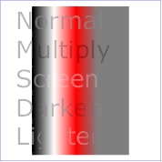
8 Filter primitive 'feBlend'
This filter composites two objects together using commonly used imaging
software blending modes. It performs a pixel-wise combination of two input
images.
Attribute definitions:
- mode = "normal | multiply | screen | darken |
lighten"
- One of the image blending modes (see table below). Default is: normal.
Animatable:yes.
- in2 = "(see in
attribute)"
- The second input image to the blending operation. This attribute can
take on the same values as the in attribute.
Animatable:yes.
For all feBlend modes, the result opacity is computed as follows:
qr = 1 - (1-qa)*(1-qb)
For the compositing formulas below, the following definitions apply:
image A = in
image B = in2
cr = Result color (RGB) - premultiplied
qa = Opacity value at a given pixel for image A
qb = Opacity value at a given pixel for image B
ca = Color (RGB) at a given pixel for image A - premultiplied
cb = Color (RGB) at a given pixel for image B - premultiplied
The following table
provides the list of available image blending modes:
ED: make table look nicer
| Image Blending Mode |
Formula for computing result color |
| normal |
cr = (1 - qa) * cb + ca |
| multiply |
cr = (1-qa)*cb + (1-qb)*ca + ca*cb |
| screen |
cr = cb + ca - ca * cb |
| darken |
cr = Min ((1 - qa) * cb + ca, (1 - qb) * ca + cb) |
| lighten |
cr = Max ((1 - qa) * cb + ca, (1 - qb) * ca + cb) |
'normal' blend mode is equivalent to operator="over" on the 'feComposite'
filter primitive, matches the blending method used by 'feMerge' and matches
the simple alpha compositing
technique used in SVG for all compositing outside of filter effects.
<?xml version="1.0"?>
<!DOCTYPE svg PUBLIC "-//W3C//DTD SVG 1.1//EN"
          "http://www.w3.org/Graphics/SVG/1.1/DTD/svg11.dtd">
<svg width="5cm" height="5cm" viewBox="0 0 500 500"
     xmlns="http://www.w3.org/2000/svg" version="1.1">
  <title>Example feBlend - Examples of feBlend modes</title>
  <desc>Five text strings blended into a gradient,
        with one text string for each of the five feBlend modes.</desc>
  <defs>
    <linearGradient id="MyGradient" gradientUnits="userSpaceOnUse"
            x1="100" y1="0" x2="300" y2="0">
      <stop offset="0" stop-color="#000000" />
      <stop offset=".33" stop-color="#ffffff" />
      <stop offset=".67" stop-color="#ff0000" />
      <stop offset="1" stop-color="#808080" />
    </linearGradient>
    <filter id="Normal">
      <feBlend mode="normal" in2="BackgroundImage" in="SourceGraphic"/>
    </filter>
    <filter id="Multiply">
      <feBlend mode="multiply" in2="BackgroundImage" in="SourceGraphic"/>
    </filter>
    <filter id="Screen">
      <feBlend mode="screen" in2="BackgroundImage" in="SourceGraphic"/>
    </filter>
    <filter id="Darken">
      <feBlend mode="darken" in2="BackgroundImage" in="SourceGraphic"/>
    </filter>
    <filter id="Lighten">
      <feBlend mode="lighten" in2="BackgroundImage" in="SourceGraphic"/>
    </filter>
  </defs>
  <rect fill="none" stroke="blue"
        x="1" y="1" width="498" height="498"/>
  <g enable-background="new" >
    <rect x="100" y="20" width="300" height="460" fill="url(#MyGradient)" />
    <g font-family="Verdana" font-size="75" fill="#888888" fill-opacity=".6" >
      <text x="50" y="90" filter="url(#Normal)" >Normal</text>
      <text x="50" y="180" filter="url(#Multiply)" >Multiply</text>
      <text x="50" y="270" filter="url(#Screen)" >Screen</text>
      <text x="50" y="360" filter="url(#Darken)" >Darken</text>
      <text x="50" y="450" filter="url(#Lighten)" >Lighten</text>
    </g>
  </g>
</svg>
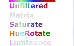
9 Filter primitive 'feColorMatrix'
This filter applies a matrix transformation:
| R' |     | a00 a01 a02 a03 a04 |   | R |
| G' |     | a10 a11 a12 a13 a14 |   | G |
| B' |  =  | a20 a21 a22 a23 a24 | * | B |
| A' |     | a30 a31 a32 a33 a34 |   | A |
| 1  |     |  0   0   0   0   1  |   | 1 |
ED: Make this in mathml, how to export? (want same look as in
coords.html)
on the RGBA color and alpha values of every pixel on the input graphics to
produce a result with a new set of RGBA color and alpha values.
The calculations are performed on non-premultiplied color values. If the
input graphics consists of premultiplied color values, those values are
automatically converted into non-premultiplied color values for this
operation.
These matrices often perform an identity mapping in the alpha channel. If
that is the case, an implementation can avoid the costly undoing and redoing
of the premultiplication for all pixels with A = 1.
Attribute definitions:
- type =
"matrix | saturate | hueRotate | luminanceToAlpha"
- Indicates the type of matrix operation. The keyword matrix indicates that a full 5x4 matrix of
values will be provided. The other keywords represent convenience
shortcuts to allow commonly used color operations to be performed
without specifying a complete matrix.
Animatable:yes.
- values =
"list of <number>s"
- The contents of values depends on the
value of attribute type:
- For type="matrix", values is a list of 20 matrix values (a00
a01 a02 a03 a04 a10 a11 ... a34), separated by whitespace and/or a
comma. For example, the identity matrix could be expressed as:
type="matrix"
values="1 0 0 0 0  0 1 0 0 0  0 0 1 0 0  0 0 0 1 0"
- For type="saturate", values is a single real number value (0 to
1). A saturate operation is
equivalent to the following matrix operation:
| R' |     |0.213+0.787s  0.715-0.715s  0.072-0.072s 0  0 |   | R |
| G' |     |0.213-0.213s  0.715+0.285s  0.072-0.072s 0  0 |   | G |
| B' |  =  |0.213-0.213s  0.715-0.715s  0.072+0.928s 0  0 | * | B |
| A' |     |           0            0             0  1  0 |   | A |
| 1  |     |           0            0             0  0  1 |   | 1 |
ED: Make this in mathml, how to export? (want same look as in
coords.html)
- For type="hueRotate", values is a single one real number value
(degrees). A hueRotate operation is
equivalent to the following matrix operation:
| R' |     | a00  a01  a02  0  0 |   | R |
| G' |     | a10  a11  a12  0  0 |   | G |
| B' |  =  | a20  a21  a22  0  0 | * | B |
| A' |     | 0    0    0    1  0 |   | A |
| 1  |     | 0    0    0    0  1 |   | 1 |
ED: Make this in mathml, how to export? (want same look as in
coords.html)
where the terms a00, a01, etc. are calculated as follows:
| a00 a01 a02 |    [+0.213 +0.715 +0.072]
| a10 a11 a12 | =  [+0.213 +0.715 +0.072] +
| a20 a21 a22 |    [+0.213 +0.715 +0.072]
                        [+0.787 -0.715 -0.072]
cos(hueRotate value) *  [-0.213 +0.285 -0.072] +
                        [-0.213 -0.715 +0.928]
                        [-0.213 -0.715+0.928]
sin(hueRotate value) *  [+0.143 +0.140-0.283]
                        [-0.787 +0.715+0.072]
ED: Make this in mathml, how to export? (want same look as in
coords.html)
Thus, the upper left term of the hue matrix turns out to be:
.213 + cos(hueRotate value)*.787 - sin(hueRotate value)*.213
ED: Make this in mathml, how to export? (want same look as in
coords.html)
- For type="luminanceToAlpha",
values is not applicable. A luminanceToAlpha operation is equivalent
to the following matrix operation:
   | R' |     |      0        0        0  0  0 |   | R |
   | G' |     |      0        0        0  0  0 |   | G |
   | B' |  =  |      0        0        0  0  0 | * | B |
   | A' |     | 0.2125   0.7154   0.0721  0  0 |   | A |
   | 1  |     |      0        0        0  0  1 |   | 1 |
ED: Make this in mathml, how to export? (want same look as in
coords.html)
If the attribute is not specified, then the default behavior depends on
the value of attribute type. If type="matrix", then this attribute defaults
to the identity matrix. If type="saturate", then this attribute defaults
to the value 1, which results in the
identify matrix. If type="hueRotate",
then this attribute defaults to the value 0, which results in the identify matrix.
Animatable:yes.
<?xml version="1.0"?>
<!DOCTYPE svg PUBLIC "-//W3C//DTD SVG 1.1//EN"
          "http://www.w3.org/Graphics/SVG/1.1/DTD/svg11.dtd">
<svg width="8cm" height="5cm" viewBox="0 0 800 500"
     xmlns="http://www.w3.org/2000/svg" version="1.1">
  <title>Example feColorMatrix - Examples of feColorMatrix operations</title>
  <desc>Five text strings showing the effects of feColorMatrix:
        an unfiltered text string acting as a reference,
        use of the feColorMatrix matrix option to convert to grayscale,
        use of the feColorMatrix saturate option,
        use of the feColorMatrix hueRotate option,
        and use of the feColorMatrix luminanceToAlpha option.</desc>
  <defs>
    <linearGradient id="MyGradient" gradientUnits="userSpaceOnUse"
            x1="100" y1="0" x2="500" y2="0">
      <stop offset="0" stop-color="#ff00ff" />
      <stop offset=".33" stop-color="#88ff88" />
      <stop offset=".67" stop-color="#2020ff" />
      <stop offset="1" stop-color="#d00000" />
    </linearGradient>
    <filter id="Matrix" filterUnits="objectBoundingBox"
            x="0%" y="0%" width="100%" height="100%">
      <feColorMatrix type="matrix" in="SourceGraphic"
           values=".33 .33 .33 0 0
                   .33 .33 .33 0 0
                   .33 .33 .33 0 0
                   .33 .33 .33 0 0"/>
    </filter>
    <filter id="Saturate40" filterUnits="objectBoundingBox"
            x="0%" y="0%" width="100%" height="100%">
      <feColorMatrix type="saturate" in="SourceGraphic" values="40%"/>
    </filter>
    <filter id="HueRotate90" filterUnits="objectBoundingBox"
            x="0%" y="0%" width="100%" height="100%">
      <feColorMatrix type="hueRotate" in="SourceGraphic" values="90"/>
    </filter>
    <filter id="LuminanceToAlpha" filterUnits="objectBoundingBox"
            x="0%" y="0%" width="100%" height="100%">
      <feColorMatrix type="luminanceToAlpha" in="SourceGraphic" result="a"/>
      <feComposite in="SourceGraphic" in2="a" operator="in" />
    </filter>
  </defs>
  <rect fill="none" stroke="blue"
        x="1" y="1" width="798" height="498"/>
  <g font-family="Verdana" font-size="75"
            font-weight="bold" fill="url(#MyGradient)" >
    <rect x="100" y="0" width="500" height="20" />
    <text x="100" y="90">Unfiltered</text>
    <text x="100" y="190" filter="url(#Matrix)" >Matrix</text>
    <text x="100" y="290" filter="url(#Saturate40)" >Saturate</text>
    <text x="100" y="390" filter="url(#HueRotate90)" >HueRotate</text>
    <text x="100" y="490" filter="url(#LuminanceToAlpha)" >Luminance</text>
  </g>
</svg>
10 Filter primitive 'feComponentTransfer'
This filter primitive performs component-wise remapping of data as
follows:
R' = feFuncR( R )
G' = feFuncG( G )
B' = feFuncB( B )
A' = feFuncA( A )
for every pixel. It allows operations like brightness adjustment, contrast
adjustment, color balance or thresholding.
The calculations are performed on non-premultiplied color values. If the
input graphics consists of premultiplied color values, those values are
automatically converted into non-premultiplied color values for this
operation. (Note that the undoing and redoing of the premultiplication can be
avoided if feFuncA is the identity transform
and all alpha values on the source graphic are set to 1.)
- The specification of the transfer functions is defined by the
sub-elements to 'feComponentTransfer':
- 'feFuncR', transfer function for
red component of the input graphic
- 'feFuncG', transfer function for
green component of the input graphic
- 'feFuncB', transfer function for
blue component of the input graphic
- 'feFuncA', transfer function for
alpha component of the input graphic
The attributes below apply to sub-elements 'feFuncR', 'feFuncG', 'feFuncB' and 'feFuncA' define the transfer functions.
Attribute definitions:
- type
= "identity | table | discrete | linear | gamma"
Indicates the type of component transfer function. The type of
function determines the applicability of the other attributes.
- For identity:
C' = C
- For table, the function is
defined by linear interpolation into a lookup table by attribute tableValues, which provides a list of
n+1 values (i.e., v0 to vn) in order
to identify n interpolation ranges. Interpolations use the
following formula.
For a value C pick a k such that:
k/N <= C < (k+1)/N
The result C' is given by:
C' = vk + (C - k/N)*N *
(vk+1 - vk)
- For discrete, the function is
defined by the step function defined by attribute tableValues, which provides a list of
n values (i.e., v0 to vn-1) in order
to identify a step function consisting of n steps. The
step function is defined by the following formula.
For a value C pick a k such that:
k/N <= C < (k+1)/N
The result C' is given by:
C' = vk
- For linear, the function is
defined by the following linear equation:
C' = slope * C + intercept
- For gamma, the function is
defined by the following exponential function:
C' = amplitude * pow(C, exponent) + offset
Animatable:yes. - tableValues = "(list of <number>s)"
- When type="table", the list of
<number>
s v0,v1,...vn, separated by white space and/or a comma, which
define the lookup table. An empty list results in an identity transfer
function. If the attribute is not specified, then the effect is as if
an empty list were provided.
Animatable:yes.
- slope = "<number>"
- When type="linear", the slope of the
linear function.
If the attribute is not specified, then the effect is as if a value of
1 were specified.
Animatable:yes.
- intercept = "<number>"
- When type="linear", the intercept of
the linear function.
If the attribute is not specified, then the effect is as if a value of
0 were specified.
Animatable:yes.
- amplitude = "<number>"
- When type="gamma", the amplitude of
the gamma function.
If the attribute is not specified, then the effect is as if a value of
1 were specified.
Animatable:yes.
- exponent = "<number>"
- When type="gamma", the exponent of
the gamma function.
If the attribute is not specified, then the effect is as if a value of
1 were specified.
Animatable:yes.
- offset = "<number>"
- When type="gamma", the offset of the
gamma function.
If the attribute is not specified, then the effect is as if a value of
0 were specified.
Animatable:yes.
- Attributes defined elsewhere:
- %stdAttrs;
, %filter_primitive_attributes_with_in;,
%PresentationAttributes-FilterPrimitives;
.
<?xml version="1.0"?>
<!DOCTYPE svg PUBLIC "-//W3C//DTD SVG 1.1//EN"
          "http://www.w3.org/Graphics/SVG/1.1/DTD/svg11.dtd">
<svg width="8cm" height="4cm" viewBox="0 0 800 400"
     xmlns="http://www.w3.org/2000/svg" version="1.1">
  <title>Example feComponentTransfer - Examples of feComponentTransfer operations</title>
  <desc>Four text strings showing the effects of feComponentTransfer:
        an identity function acting as a reference,
        use of the feComponentTransfer table option,
        use of the feComponentTransfer linear option,
        and use of the feComponentTransfer gamma option.</desc>
  <defs>
    <linearGradient id="MyGradient" gradientUnits="userSpaceOnUse"
            x1="100" y1="0" x2="600" y2="0">
      <stop offset="0" stop-color="#ff0000" />
      <stop offset=".33" stop-color="#00ff00" />
      <stop offset=".67" stop-color="#0000ff" />
      <stop offset="1" stop-color="#000000" />
    </linearGradient>
    <filter id="Identity" filterUnits="objectBoundingBox"
            x="0%" y="0%" width="100%" height="100%">
      <feComponentTransfer>
        <feFuncR type="identity"/>
        <feFuncG type="identity"/>
        <feFuncB type="identity"/>
        <feFuncA type="identity"/>
      </feComponentTransfer>
    </filter>
    <filter id="Table" filterUnits="objectBoundingBox"
            x="0%" y="0%" width="100%" height="100%">
      <feComponentTransfer>
        <feFuncR type="table" tableValues="0 0 1 1"/>
        <feFuncG type="table" tableValues="1 1 0 0"/>
        <feFuncB type="table" tableValues="0 1 1 0"/>
      </feComponentTransfer>
    </filter>
    <filter id="Linear" filterUnits="objectBoundingBox"
            x="0%" y="0%" width="100%" height="100%">
      <feComponentTransfer>
        <feFuncR type="linear" slope=".5" intercept=".25"/>
        <feFuncG type="linear" slope=".5" intercept="0"/>
        <feFuncB type="linear" slope=".5" intercept=".5"/>
      </feComponentTransfer>
    </filter>
    <filter id="Gamma" filterUnits="objectBoundingBox"
            x="0%" y="0%" width="100%" height="100%">
      <feComponentTransfer>
        <feFuncR type="gamma" amplitude="2" exponent="5" offset="0"/>
        <feFuncG type="gamma" amplitude="2" exponent="3" offset="0"/>
        <feFuncB type="gamma" amplitude="2" exponent="1" offset="0"/>
      </feComponentTransfer>
    </filter>
  </defs>
  <rect fill="none" stroke="blue"
        x="1" y="1" width="798" height="398"/>
  <g font-family="Verdana" font-size="75"
            font-weight="bold" fill="url(#MyGradient)" >
    <rect x="100" y="0" width="600" height="20" />
    <text x="100" y="90">Identity</text>
    <text x="100" y="190" filter="url(#Table)" >TableLookup</text>
    <text x="100" y="290" filter="url(#Linear)" >LinearFunc</text>
    <text x="100" y="390" filter="url(#Gamma)" >GammaFunc</text>
  </g>
</svg>

11 Filter primitive 'feComposite'
This filter performs the combination of the two input images pixel-wise in
image space using one of the Porter-Duff [PORTERDUFF] compositing operations: over, in,
atop, out, xor. Additionally, a component-wise arithmetic
operation (with the result clamped between [0..1]) can be applied.
The arithmetic operation is useful for combining the output from
the 'feDiffuseLighting' and 'feSpecularLighting' filters with texture
data. It is also useful for implementing dissolve. If the
arithmetic operation is chosen, each result pixel is computed using
the following formula:
result = k1*i1*i2 + k2*i1 + k3*i2 + k4
For this filter primitive, the extent of the resulting image might grow as
described in the section that describes the filter primitive subregion.
Attribute definitions:
- operator
= "over | in | out | atop | xor | arithmetic"
- The compositing operation that is to be performed. All of the operator types except arithmetic match the correspond operation as
described in [PORTERDUFF]. The arithmetic operator is described above.
Animatable:yes.
- k1 = "<number>"
- Only applicable if operator="arithmetic".
If the attribute is not specified, the effect is as if a value of "0"
were specified.
Animatable:yes.
- k2 = "<number>"
- Only applicable if operator="arithmetic".
If the attribute is not specified, the effect is as if a value of "0"
were specified.
Animatable:yes.
- k3 = "<number>"
- Only applicable if operator="arithmetic".
If the attribute is not specified, the effect is as if a value of "0"
were specified.
Animatable:yes.
- k4 = "<number>"
- Only applicable if operator="arithmetic".
If the attribute is not specified, the effect is as if a value of "0"
were specified.
Animatable:yes.
-
in2 = "(see in
attribute)"
- The second input image to the compositing operation. This attribute
can take on the same values as the in attribute.
Animatable:yes.
<?xml version="1.0"?>
<!DOCTYPE svg PUBLIC "-//W3C//DTD SVG 1.1//EN"
          "http://www.w3.org/Graphics/SVG/1.1/DTD/svg11.dtd">
<svg width="330" height="195" viewBox="0 0 1100 650" version="1.1"
     xmlns="http://www.w3.org/2000/svg" xmlns:xlink="http://www.w3.org/1999/xlink">
  <title>Example feComposite - Examples of feComposite operations</title>
  <desc>Four rows of six pairs of overlapping triangles depicting
        the six different feComposite operators under different
        opacity values and different clearing of the background.</desc>
	<defs>
    <desc>Define two sets of six filters for each of the six compositing operators.
          The first set wipes out the background image by flooding with opaque white.
          The second set does not wipe out the background, with the result
          that the background sometimes shines through and is other cases
          is blended into itself (i.e., "double-counting").</desc>
    <filter id="overFlood" filterUnits="objectBoundingBox" x="-5%" y="-5%" width="110%" height="110%">
      <feFlood flood-color="#ffffff" flood-opacity="1" result="flood"/>
      <feComposite in="SourceGraphic" in2="BackgroundImage" operator="over" result="comp"/>
      <feMerge> <feMergeNode in="flood"/> <feMergeNode in="comp"/> </feMerge>
    </filter>
    <filter id="inFlood" filterUnits="objectBoundingBox" x="-5%" y="-5%" width="110%" height="110%">
      <feFlood flood-color="#ffffff" flood-opacity="1" result="flood"/>
      <feComposite in="SourceGraphic" in2="BackgroundImage" operator="in" result="comp"/>
      <feMerge> <feMergeNode in="flood"/> <feMergeNode in="comp"/> </feMerge>
    </filter>
    <filter id="outFlood" filterUnits="objectBoundingBox" x="-5%" y="-5%" width="110%" height="110%">
      <feFlood flood-color="#ffffff" flood-opacity="1" result="flood"/>
      <feComposite in="SourceGraphic" in2="BackgroundImage" operator="out" result="comp"/>
      <feMerge> <feMergeNode in="flood"/> <feMergeNode in="comp"/> </feMerge>
    </filter>
    <filter id="atopFlood" filterUnits="objectBoundingBox" x="-5%" y="-5%" width="110%" height="110%">
      <feFlood flood-color="#ffffff" flood-opacity="1" result="flood"/>
      <feComposite in="SourceGraphic" in2="BackgroundImage" operator="atop" result="comp"/>
      <feMerge> <feMergeNode in="flood"/> <feMergeNode in="comp"/> </feMerge>
    </filter>
    <filter id="xorFlood" filterUnits="objectBoundingBox" x="-5%" y="-5%" width="110%" height="110%">
      <feFlood flood-color="#ffffff" flood-opacity="1" result="flood"/>
      <feComposite in="SourceGraphic" in2="BackgroundImage" operator="xor" result="comp"/>
      <feMerge> <feMergeNode in="flood"/> <feMergeNode in="comp"/> </feMerge>
    </filter>
    <filter id="arithmeticFlood" filterUnits="objectBoundingBox"
            x="-5%" y="-5%" width="110%" height="110%">
      <feFlood flood-color="#ffffff" flood-opacity="1" result="flood"/>
      <feComposite in="SourceGraphic" in2="BackgroundImage" result="comp"
                   operator="arithmetic" k1=".5" k2=".5" k3=".5" k4=".5"/>
      <feMerge> <feMergeNode in="flood"/> <feMergeNode in="comp"/> </feMerge>
    </filter>
    <filter id="overNoFlood" filterUnits="objectBoundingBox" x="-5%" y="-5%" width="110%" height="110%">
      <feComposite in="SourceGraphic" in2="BackgroundImage" operator="over" result="comp"/>
    </filter>
    <filter id="inNoFlood" filterUnits="objectBoundingBox" x="-5%" y="-5%" width="110%" height="110%">
      <feComposite in="SourceGraphic" in2="BackgroundImage" operator="in" result="comp"/>
    </filter>
    <filter id="outNoFlood" filterUnits="objectBoundingBox" x="-5%" y="-5%" width="110%" height="110%">
      <feComposite in="SourceGraphic" in2="BackgroundImage" operator="out" result="comp"/>
    </filter>
    <filter id="atopNoFlood" filterUnits="objectBoundingBox" x="-5%" y="-5%" width="110%" height="110%">
      <feComposite in="SourceGraphic" in2="BackgroundImage" operator="atop" result="comp"/>
    </filter>
    <filter id="xorNoFlood" filterUnits="objectBoundingBox" x="-5%" y="-5%" width="110%" height="110%">
      <feComposite in="SourceGraphic" in2="BackgroundImage" operator="xor" result="comp"/>
    </filter>
    <filter id="arithmeticNoFlood" filterUnits="objectBoundingBox"
            x="-5%" y="-5%" width="110%" height="110%">
      <feComposite in="SourceGraphic" in2="BackgroundImage" result="comp"
                   operator="arithmetic" k1=".5" k2=".5" k3=".5" k4=".5"/>
    </filter>
    <path id="Blue100" d="M 0 0 L 100 0 L 100 100 z" fill="#00ffff" />
    <path id="Red100" d="M 0 0 L 0 100 L 100 0 z" fill="#ff00ff" />
    <path id="Blue50" d="M 0 125 L 100 125 L 100 225 z" fill="#00ffff" fill-opacity=".5" />
    <path id="Red50" d="M 0 125 L 0 225 L 100 125 z" fill="#ff00ff" fill-opacity=".5" />
    <g id="TwoBlueTriangles">
      <use xlink:href="#Blue100"/>
      <use xlink:href="#Blue50"/>
    </g>
    <g id="BlueTriangles">
      <use transform="translate(275,25)" xlink:href="#TwoBlueTriangles"/>
      <use transform="translate(400,25)" xlink:href="#TwoBlueTriangles"/>
      <use transform="translate(525,25)" xlink:href="#TwoBlueTriangles"/>
      <use transform="translate(650,25)" xlink:href="#TwoBlueTriangles"/>
      <use transform="translate(775,25)" xlink:href="#TwoBlueTriangles"/>
      <use transform="translate(900,25)" xlink:href="#TwoBlueTriangles"/>
    </g>
  </defs>

  <rect fill="none" stroke="blue" x="1" y="1" width="1098" height="648"/>
  <g font-family="Verdana" font-size="40" shape-rendering="crispEdges">
    <desc>Render the examples using the filters that draw on top of
          an opaque white surface, thus obliterating the background.</desc>
    <g enable-background="new">
      <text x="15" y="75">opacity 1.0</text>
      <text x="15" y="115" font-size="27">(with feFlood)</text>
      <text x="15" y="200">opacity 0.5</text>
      <text x="15" y="240" font-size="27">(with feFlood)</text>
      <use xlink:href="#BlueTriangles"/>
      <g transform="translate(275,25)">
        <use xlink:href="#Red100" filter="url(#overFlood)" />
        <use xlink:href="#Red50" filter="url(#overFlood)" />
        <text x="5" y="275">over</text>
      </g>
      <g transform="translate(400,25)">
        <use xlink:href="#Red100" filter="url(#inFlood)" />
        <use xlink:href="#Red50" filter="url(#inFlood)" />
        <text x="35" y="275">in</text>
      </g>
      <g transform="translate(525,25)">
        <use xlink:href="#Red100" filter="url(#outFlood)" />
        <use xlink:href="#Red50" filter="url(#outFlood)" />
        <text x="15" y="275">out</text>
      </g>
      <g transform="translate(650,25)">
        <use xlink:href="#Red100" filter="url(#atopFlood)" />
        <use xlink:href="#Red50" filter="url(#atopFlood)" />
        <text x="10" y="275">atop</text>
      </g>
      <g transform="translate(775,25)">
        <use xlink:href="#Red100" filter="url(#xorFlood)" />
        <use xlink:href="#Red50" filter="url(#xorFlood)" />
        <text x="15" y="275">xor</text>
      </g>
      <g transform="translate(900,25)">
        <use xlink:href="#Red100" filter="url(#arithmeticFlood)" />
        <use xlink:href="#Red50" filter="url(#arithmeticFlood)" />
        <text x="-25" y="275">arithmetic</text>
      </g>
    </g>
    <g transform="translate(0,325)" enable-background="new">
    <desc>Render the examples using the filters that do not obliterate
          the background, thus sometimes causing the background to continue
          to appear in some cases, and in other cases the background
          image blends into itself ("double-counting").</desc>
      <text x="15" y="75">opacity 1.0</text>
      <text x="15" y="115" font-size="27">(without feFlood)</text>
      <text x="15" y="200">opacity 0.5</text>
      <text x="15" y="240" font-size="27">(without feFlood)</text>
      <use xlink:href="#BlueTriangles"/>
      <g transform="translate(275,25)">
        <use xlink:href="#Red100" filter="url(#overNoFlood)" />
        <use xlink:href="#Red50" filter="url(#overNoFlood)" />
        <text x="5" y="275">over</text>
      </g>
      <g transform="translate(400,25)">
        <use xlink:href="#Red100" filter="url(#inNoFlood)" />
        <use xlink:href="#Red50" filter="url(#inNoFlood)" />
        <text x="35" y="275">in</text>
      </g>
      <g transform="translate(525,25)">
        <use xlink:href="#Red100" filter="url(#outNoFlood)" />
        <use xlink:href="#Red50" filter="url(#outNoFlood)" />
        <text x="15" y="275">out</text>
      </g>
      <g transform="translate(650,25)">
        <use xlink:href="#Red100" filter="url(#atopNoFlood)" />
        <use xlink:href="#Red50" filter="url(#atopNoFlood)" />
        <text x="10" y="275">atop</text>
      </g>
      <g transform="translate(775,25)">
        <use xlink:href="#Red100" filter="url(#xorNoFlood)" />
        <use xlink:href="#Red50" filter="url(#xorNoFlood)" />
        <text x="15" y="275">xor</text>
      </g>
      <g transform="translate(900,25)">
        <use xlink:href="#Red100" filter="url(#arithmeticNoFlood)" />
        <use xlink:href="#Red50" filter="url(#arithmeticNoFlood)" />
        <text x="-25" y="275">arithmetic</text>
      </g>
    </g>
  </g>
</svg>
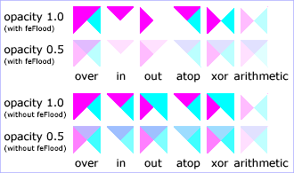
12 Filter primitive 'feConvolveMatrix'
feConvolveMatrix applies a matrix convolution filter effect. A convolution
combines pixels in the input image with neighboring pixels to produce a
resulting image. A wide variety of imaging operations can be achieved through
convolutions, including blurring, edge detection, sharpening, embossing and
beveling.
A matrix convolution is based on an n-by-m matrix (the convolution kernel)
which describes how a given pixel value in the input image is combined with
its neighboring pixel values to produce a resulting pixel value. Each result
pixel is determined by applying the kernel matrix to the corresponding source
pixel and its neighboring pixels. The basic convolution formula which is
applied to each color value for a given pixel is:
RESULTX,Y = (
SUM I=0 to [orderY-1] {
SUM J=0 to [orderX-1] {
SOURCE X-targetX+J, Y-targetY+I * kernelMatrixorderX-J-1, orderY-I-1
}
}
) / divisor + bias
ED: Consider making this into mathml
where "orderX" and "orderY" represent the X and Y values for the order attribute, "targetX" represents the value
of the targetX attribute, "targetY" represents the
value of the targetY attribute, "kernelMatrix" represents the
value of the kernelMatrix attribute, "divisor" represents the
value of the divisor attribute, and "bias" represents the
value of the bias attribute.
Note in the above formulas that the values in the kernel matrix are
applied such that the kernel matrix is rotated 180 degrees relative to the
source and destination images in order to match convolution theory as
described in many computer graphics textbooks.
To illustrate, suppose you have a input image which is 5 pixels by 5
pixels, whose color values for one of the color channels are as follows:
    0  20  40 235 235
  100 120 140 235 235
  200 220 240 235 235
  225 225 255 255 255
  225 225 255 255 255
ED: Consider making this into mathml
and you define a 3-by-3 convolution kernel as follows:
  1 2 3
  4 5 6
  7 8 9
ED: Consider making this into mathml
Let's focus on the color value at the second row and second column of the
image (source pixel value is 120). Assuming the simplest case (where the
input image's pixel grid aligns perfectly with the kernel's pixel grid) and
assuming default values for attributes divisor, targetX and
targetY, then resulting color value will
be:
(9*  0 + 8* 20 + 7* 40 +
6*100 + 5*120 + 4*140 +
3*200 + 2*220 + 1*240) / (9+8+7+6+5+4+3+2+1)
ED: Consider making this into mathml
Because they operate on pixels, matrix convolutions are inherently
resolution-dependent. To make 'feConvolveMatrix produce resolution-independent
results, an explicit value should be provided for either the filterRes attribute on the 'filter' element
and/or attribute kernelUnitLength.
kernelUnitLength, in combination with the other
attributes, defines an implicit pixel grid in the filter effects coordinate
system (i.e., the coordinate system established by the primitiveUnits attribute). If the pixel grid
established by kernelUnitLength is not scaled to match the
pixel grid established by attribute filterRes (implicitly or explicitly), then the
input image will be temporarily rescaled to match its pixels with kernelUnitLength. The convolution happens on the
resampled image. After applying the convolution, the image is resampled back
to the original resolution.
When the image must be resampled to match the coordinate system defined by
kernelUnitLength prior to convolution, or
resampled to match the device coordinate system after convolution, it is
recommended that high quality viewers make use of appropriate interpolation
techniques, for example bilinear or bicubic. Depending on the speed of the
available interpolents, this choice may be affected by the 'image-rendering' property setting. Note that
implementations might choose approaches that minimize or eliminate resampling
when not necessary to produce proper results, such as when the document is
zoomed out such that kernelUnitLength is
considerably smaller than a device pixel.
Attribute definitions:
- order = "<number-optional-number>"
- Indicates the number of cells in each dimension for kernelMatrix. The values provided must be
<integer>
s greater than zero. The first number, <orderX>, indicates the
number of columns in the matrix. The second number, <orderY>,
indicates the number of rows in the matrix. If <orderY> is not
provided, it defaults to <orderX>.
A typical value is order="3". It is recommended that only small values
(e.g., 3) be used; higher values may result in very high CPU overhead
and usually do not produce results that justify the impact on
performance.
If the attribute is not specified, the effect is as if a value of "3"
were specified.
Animatable:yes.
- kernelMatrix = "<list of
numbers>"
- The list of <number>
s that make up the kernel matrix for the convolution. Values are
separated by space characters and/or a comma. The number of entries in
the list must equal <orderX> times <orderY>.
Animatable:yes.
- divisor = "<number>"
- After applying the kernelMatrix to the
input image to yield a number, that number is divided by divisor to yield the final destination color
value. A divisor that is the sum of all the matrix values tends to have
an evening effect on the overall color intensity of the result. If the
specified divisor is zero then the default value will be used instead.
The default value is the sum of all values in kernelMatrix, with the
exception that if the sum is zero, then the divisor is set to 1.
Animatable:yes.
- bias = "<number>"
- After applying the kernelMatrix to the
input image to yield a number and applying the divisor, the bias attribute is added to each component. One
application of bias is when it is
desirable to have .5 gray value be the zero response of the filter. If
bias is not specified, then the effect
is as if a value of zero were specified.
Animatable:yes.
- targetX = "<integer>"
- Determines the positioning in X of the convolution matrix relative to
a given target pixel in the input image. The leftmost column of the
matrix is column number zero. The value must be such that: 0 <=
targetX < orderX. By default, the convolution matrix is centered in
X over each pixel of the input image (i.e., targetX = floor ( orderX /
2 )).
Animatable:yes.
- targetY = "<integer>"
- Determines the positioning in Y of the convolution matrix relative to
a given target pixel in the input image. The topmost row of the matrix
is row number zero. The value must be such that: 0 <= targetY <
orderY. By default, the convolution matrix is centered in Y over each
pixel of the input image (i.e., targetY = floor ( orderY / 2 )).
Animatable:yes.
- edgeMode = "duplicate | wrap |
none"
Determines how to extend the input image as necessary with color
values so that the matrix operations can be applied when the kernel is
positioned at or near the edge of the input image.
"duplicate" indicates that the input image is extended along each of
its borders as necessary by duplicating the color values at the given
edge of the input image.
Original N-by-M image, where m=M-1 and n=N-1:
          11 12 ... 1m 1M
          21 22 ... 2m 2M
          .. .. ... .. ..
          n1 n2 ... nm nM
          N1 N2 ... Nm NM
Extended by two pixels using "duplicate":
  11 11   11 12 ... 1m 1M   1M 1M
  11 11   11 12 ... 1m 1M   1M 1M
  11 11   11 12 ... 1m 1M   1M 1M
  21 21   21 22 ... 2m 2M   2M 2M
  .. ..   .. .. ... .. ..   .. ..
  n1 n1   n1 n2 ... nm nM   nM nM
  N1 N1   N1 N2 ... Nm NM   NM NM
  N1 N1   N1 N2 ... Nm NM   NM NM
  N1 N1   N1 N2 ... Nm NM   NM NM
ED: Consider making this into mathml
"wrap" indicates that the input image is extended by taking the
color values from the opposite edge of the image.
Extended by two pixels using "wrap":
  nm nM   n1 n2 ... nm nM   n1 n2
  Nm NM   N1 N2 ... Nm NM   N1 N2
  1m 1M   11 12 ... 1m 1M   11 12
  2m 2M   21 22 ... 2m 2M   21 22
  .. ..   .. .. ... .. ..   .. ..
  nm nM   n1 n2 ... nm nM   n1 n2
  Nm NM   N1 N2 ... Nm NM   N1 N2
  1m 1M   11 12 ... 1m 1M   11 12
  2m 2M   21 22 ... 2m 2M   21 22
ED: Consider making this into mathml
"none" indicates that the input image is extended with pixel values
of zero for R, G, B and A.
Animatable:yes.
- kernelUnitLength = "<number-optional-number>"
- The first number is the <dx> value. The second number is the
<dy> value. If the <dy> value is not specified, it defaults
to the same value as <dx>. Indicates the intended distance in
current filter units (i.e., units as determined by the value of
attribute primitiveUnits) between successive columns
and rows, respectively, in the kernelMatrix. By specifying value(s) for kernelUnitLength, the kernel becomes defined
in a scalable, abstract coordinate system. If kernelUnitLength is not specified, the default
value is one pixel in the offscreen bitmap, which is a pixel-based
coordinate system, and thus potentially not scalable. For some level of
consistency across display media and user agents, it is necessary that
a value be provided for at least one of filterRes and kernelUnitLength. In some implementations, the
most consistent results and the fastest performance will be achieved if
the pixel grid of the temporary offscreen images aligns with the pixel
grid of the kernel.
If a negative or zero value is specified the default value will be used
instead.
Animatable:yes.
- preserveAlpha = "false |
true"
- A value of false indicates that the
convolution will apply to all channels, including the alpha channel.
A value of true indicates that the
convolution will only apply to the color channels. In this case, the
filter will temporarily unpremultiply the color component values, apply
the kernel, and then re-premultiply at the end.
If preserveAlpha is not specified, then
the effect is as if a value of false
were specified.
Animatable:yes.
13 Filter primitive 'feDiffuseLighting'
This filter primitive lights an image using the alpha channel as a bump
map. The resulting image is an RGBA opaque image based on the light color
with alpha = 1.0 everywhere. The lighting calculation follows the standard
diffuse component of the Phong lighting model. The resulting image depends on
the light color, light position and surface geometry of the input bump
map.
The light map produced by this filter primitive can be combined with a
texture image using the multiply term of the arithmetic 'feComposite' compositing method. Multiple
light sources can be simulated by adding several of these light maps together
before applying it to the texture image.
The formulas below make use of 3x3 filters. Because they operate on
pixels, such filters are inherently resolution-dependent. To make 'feDiffuseLighting' produce
resolution-independent results, an explicit value should be provided for
either the filterRes attribute on the 'filter' element
and/or attribute kernelUnitLength.
kernelUnitLength, in combination with the other
attributes, defines an implicit pixel grid in the filter effects coordinate
system (i.e., the coordinate system established by the primitiveUnits attribute). If the pixel grid
established by kernelUnitLength is not scaled to match the
pixel grid established by attribute filterRes (implicitly or explicitly), then the
input image will be temporarily rescaled to match its pixels with kernelUnitLength. The 3x3 filters are applied to
the resampled image. After applying the filter, the image is resampled back
to its original resolution.
When the image must be resampled, it is recommended that high quality
viewers make use of appropriate interpolation techniques, for example
bilinear or bicubic. Depending on the speed of the available interpolents,
this choice may be affected by the 'image-rendering' property setting. Note that
implementations might choose approaches that minimize or eliminate resampling
when not necessary to produce proper results, such as when the document is
zoomed out such that kernelUnitLength is
considerably smaller than a device pixel.
For the formulas that follow, the
Norm(Ax,Ay,Az) function is
defined as:
ED: Consider making the following in mathml
Norm(Ax,Ay,Az) =
sqrt(Ax^2+Ay^2+Az^2)
The resulting RGBA image is computed as follows:
Dr = kd * N.L *
Lr
Dg = kd * N.L * Lg
Db = kd * N.L * Lb
Da = 1.0
where
- kd = diffuse lighting constant
N = surface normal unit vector, a function of x and y
L = unit vector pointing from surface to light, a function of x and y
in the point and spot light cases
Lr,Lg,Lb = RGB components of light, a
function of x and y in the spot light case
N is a function of x and y and depends on the surface gradient as
follows:
The surface described by the input alpha image Ain (x,y) is:
Z (x,y) = surfaceScale * Ain (x,y)
Surface normal is calculated using the Sobel gradient 3x3 filter.
Different filter kernels are used depending on whether the given pixel is on
the interior or an edge. For each case, the formula is:
Nx (x,y)= - surfaceScale *
FACTORx *
(K x(0,0)*I(x-dx,y-dy) +
Kx(1,0)*I(x,y-dy) + Kx(2,0)*I(x+dx,y-dy) +
K x(0,1)*I(x-dx,y) +
Kx(1,1)*I(x,y) + Kx(2,1)*I(x+dx,y) +
K x(0,2)*I(x-dx,y+dy) +
Kx(1,2)*I(x,y+dy) + Kx(2,2)*I(x+dx,y+dy))
Ny (x,y)= - surfaceScale * FACTORy *
(K y(0,0)*I(x-dx,y-dy) +
Ky(1,0)*I(x,y-dy) + Ky(2,0)*I(x+dx,y-dy) +
K y(0,1)*I(x-dx,y) +
Ky(1,1)*I(x,y) + Ky(2,1)*I(x+dx,y) +
K y(0,2)*I(x-dx,y+dy) +
Ky(1,2)*I(x,y+dy) + Ky(2,2)*I(x+dx,y+dy))
Nz (x,y) = 1.0
N = (Nx, Ny, Nz) /
Norm((Nx,Ny,Nz))
In these formulas, the dx and dy values (e.g.,
I(x-dx,y-dy)), represent deltas relative to a given
(x,y) position for the purpose of estimating the slope of the
surface at that point. These deltas are determined by the value (explicit or
implicit) of attribute kernelUnitLength.
Top/left corner:
FACTORx=2/(3*dx)
Kx =
| 0 0 0 |
| 0 -2 2 |
| 0 -1 1 |
FACTORy=2/(3*dy)
Ky =
| 0 0 0 |
| 0 -2 -1 |
| 0 2 1 |
|
Top row:
FACTORx=1/(3*dx)
Kx =
| 0 0 0 |
| -2 0 2 |
| -1 0 1 |
FACTORy=1/(2*dy)
Ky =
| 0 0 0 |
| -1 -2 -1 |
| 1 2 1 |
|
Top/right corner:
FACTORx=2/(3*dx)
Kx =
| 0 0 0 |
| -2 2 0 |
| -1 1 0 |
FACTORy=2/(3*dy)
Ky =
| 0 0 0 |
| -1 -2 0 |
| 1 2 0 |
|
Left column:
FACTORx=1/(2*dx)
Kx =
| 0 -1 1 |
| 0 -2 2 |
| 0 -1 1 |
FACTORy=1/(3*dy)
Ky =
| 0 -2 -1 |
| 0 0 0 |
| 0 2 1 |
|
Interior pixels:
FACTORx=1/(4*dx)
Kx =
| -1 0 1 |
| -2 0 2 |
| -1 0 1 |
FACTORy=1/(4*dy)
Ky =
| -1 -2 -1 |
| 0 0 0 |
| 1 2 1 |
|
Right column:
FACTORx=1/(2*dx)
Kx =
| -1 1 0|
| -2 2 0|
| -1 1 0|
FACTORy=1/(3*dy)
Ky =
| -1 -2 0 |
| 0 0 0 |
| 1 2 0 |
|
Bottom/left corner:
FACTORx=2/(3*dx)
Kx =
| 0 -1 1 |
| 0 -2 2 |
| 0 0 0 |
FACTORy=2/(3*dy)
Ky =
| 0 -2 -1 |
| 0 2 1 |
| 0 0 0 |
|
Bottom row:
FACTORx=1/(3*dx)
Kx =
| -1 0 1 |
| -2 0 2 |
| 0 0 0 |
FACTORy=1/(2*dy)
Ky =
| -1 -2 -1 |
| 1 2 1 |
| 0 0 0 |
|
Bottom/right corner:
FACTORx=2/(3*dx)
Kx =
| -1 1 0 |
| -2 2 0 |
| 0 0 0 |
FACTORy=2/(3*dy)
Ky =
| -1 -2 0 |
| 1 2 0 |
| 0 0 0 |
|
L, the unit vector from the image sample to the light, is calculated as
follows:
For Infinite light sources it is constant:
Lx = cos(azimuth)*cos(elevation)
Ly = sin(azimuth)*cos(elevation)
Lz = sin(elevation)
For Point and spot lights it is a function of position:
Lx = Lightx - x
Ly = Lighty - y
Lz = Lightz - Z(x,y)
L = (Lx, Ly, Lz) / Norm(Lx,
Ly, Lz)
where Lightx, Lighty, and Lightz are the
input light position.
Lr,Lg,Lb, the light color vector, is a
function of position in the spot light case only:
Lr =
Lightr*pow((-L.S),specularExponent)
Lg = Lightg*pow((-L.S),specularExponent)
Lb = Lightb*pow((-L.S),specularExponent)
where S is the unit vector pointing from the light to the point
(pointsAtX, pointsAtY, pointsAtZ) in the x-y plane:
Sx = pointsAtX - Lightx
Sy = pointsAtY - Lighty
Sz = pointsAtZ - Lightz
S = (Sx, Sy, Sz) / Norm(Sx,
Sy, Sz)
If L.S is positive, no light is present. (Lr = Lg =
Lb = 0)
Attribute definitions:
- surfaceScale = "<number>"
- height of surface when Ain = 1.
If the attribute is not specified, then the effect is as if a value of
1 were specified.
Animatable:yes.
- diffuseConstant = "<number>"
- kd in Phong lighting model. In SVG, this can be any non-negative
number.
If the attribute is not specified, then the effect is as if a value of
1 were specified.
Animatable:yes.
- kernelUnitLength = "<number-optional-number>"
- The first number is the <dx> value. The second number is the
<dy> value. If the <dy> value is not specified, it defaults
to the same value as <dx>. Indicates the intended distance in
current filter units (i.e., units as determined by the value of
attribute primitiveUnits) for
dx and
dy, respectively, in the surface normal calculation
formulas. By specifying value(s) for kernelUnitLength, the kernel becomes defined
in a scalable, abstract coordinate system. If kernelUnitLength is not specified, the
dx and dy values should represent very small
deltas relative to a given (x,y) position, which might be
implemented in some cases as one pixel in the intermediate image
offscreen bitmap, which is a pixel-based coordinate system, and thus
potentially not scalable. For some level of consistency across display
media and user agents, it is necessary that a value be provided for at
least one of filterRes and kernelUnitLength. Discussion of intermediate
images are in the Introduction and in the
description of attribute filterRes.
If a negative or zero value is specified the default value will be used
instead.
Animatable:yes.
The light source is defined by one of the child elements 'feDistantLight', 'fePointLight' or 'feSpotLight'. The light color is specified
by property 'lighting-color'.
14 Filter primitive 'feDisplacementMap'
This filter primitive uses the pixels values from the image from in2
to spatially displace the image from in.
This is the transformation to be performed:
P'(x,y) ← P( x + scale * (XC(x,y) - .5), y + scale * (YC(x,y) - .5))
where P(x,y) is the input image, in, and
P'(x,y) is the destination. XC(x,y) and YC(x,y) are the component values of
the designated by the xChannelSelector and
yChannelSelector. For example, to use the R component of in2
to control displacement in x and the G component of Image2 to control
displacement in y, set xChannelSelector to "R" and
yChannelSelector to "G".
The displacement map, in2, defines the inverse of the mapping
performed.
The calculations using the pixel values from in2
are performed using non-premultiplied color values. If the image from in2
consists of premultiplied color values, those values are automatically
converted into non-premultiplied color values before performing this
operation.
This filter can have arbitrary non-localized effect on the input which
might require substantial buffering in the processing pipeline. However with
this formulation, any intermediate buffering needs can be determined by
scale which represents the maximum range of displacement in either x
or y.
When applying this filter, the source pixel location will often lie
between several source pixels. In this case it is recommended that high
quality viewers apply an interpolent on the surrounding pixels, for example
bilinear or bicubic, rather than simply selecting the nearest source pixel.
Depending on the speed of the available interpolents, this choice may be
affected by the 'image-rendering' property
setting.
The 'color-interpolation-filters' property
only applies to the in2 source image and does not apply to the in
source image.
Attribute definitions:
- scale
= "<number>"
- Displacement scale factor. The amount is expressed in the coordinate
system established by attribute primitiveUnits on the 'filter'
element.
When the value of this attribute is 0,
this operation has no effect on the source image.
If the attribute is not specified, then the effect is as if a value of
0 were specified.
Animatable:yes.
- xChannelSelector = "R | G | B | A"
- Indicates which channel from in2 to use to displace the pixels in in along the x-axis.
Animatable:yes.
- yChannelSelector = "R | G | B | A"
- Indicates which channel from in2 to use to displace the pixels in in along the y-axis.
Animatable:yes.
- in2 =
"(see in attribute)"
- The second input image, which is used to displace the pixels in the
image from attribute in. This attribute can take on the same
values as the in attribute.
Animatable:yes.
15 Filter primitive 'feFlood'
This filter primitive creates a rectangle filled with the color and
opacity values from properties 'flood-color'
and 'flood-opacity'. The rectangle is as large
as the filter primitive subregion
established by the 'feFlood' element.
The 'flood-color' property indicates what
color to use to flood the current filter
primitive subregion. The keyword currentColor and ICC colors can be specified in the
same manner as within a <paint> specification for the 'fill' and 'stroke'
properties.
- 'flood-color'
-
| Value: |
currentColor |
<color>
[icc-color(<name>[,<icccolorvalue>]*)] |
inherit |
| Initial: |
black |
| Applies to: |
'feFlood' and 'feDropShadow' elements |
| Inherited: |
no |
| Percentages: |
N/A |
| Media: |
visual |
| Animatable: |
yes |
The 'flood-opacity' property defines the
opacity value to use across the entire filter primitive subregion.
16 Filter primitive 'feGaussianBlur'
This filter primitive performs a Gaussian blur on the input image.
The Gaussian blur kernel is an approximation of the normalized
convolution:
H(x) = exp(-x2/ (2s2)) /
sqrt(2* pi*s2)
where 's' is the standard deviation specified by stdDeviation.
The value of stdDeviation can be either one or two numbers.
If two numbers are provided, the first number represents a standard deviation
value along the x-axis of the current coordinate system and the second value
represents a standard deviation in Y. If one number is provided, then that
value is used for both X and Y.
Even if only one value is provided for stdDeviation, this can be implemented as a
separable convolution.
For larger values of 's' (s >= 2.0), an approximation can be used:
Three successive box-blurs build a piece-wise quadratic convolution kernel,
which approximates the Gaussian kernel to within roughly 3%.
let d = floor(s * 3*sqrt(2*pi)/4 + 0.5)
... if d is odd, use three box-blurs of size 'd', centered on the output
pixel.
... if d is even, two box-blurs of size 'd' (the first one centered on the
pixel boundary between the output pixel and the one to the left, the second
one centered on the pixel boundary between the output pixel and the one to
the right) and one box blur of size 'd+1' centered on the output pixel.
Frequently this operation will take place on alpha-only images, such as
that produced by the built-in input, SourceAlpha. The implementation may notice this
and optimize the single channel case. If the input has infinite extent and is
constant, this operation has no effect. If the input has infinite extent and
is a tile, the filter is evaluated with periodic boundary conditions.
Attribute definitions:
- stdDeviation =
"<number-optional-number>"
- The standard deviation for the blur operation. If two <number>
s are provided, the first number represents a standard deviation value
along the x-axis of the coordinate system established by attribute primitiveUnits on the 'filter'
element. The second value represents a standard deviation in Y. If one
number is provided, then that value is used for both X and Y.
A negative or zero value disables the effect of the given filter
primitive (i.e., the result is a transparent black image).
If the attribute is not specified, then the effect is as if a value of
0 were specified.
Animatable:yes.
The example at the start of this chapter makes
use of the feGaussianBlur filter primitive
to create a drop shadow effect.
17 Filter primitive 'feImage'
This filter primitive refers to a graphic external to this filter element,
which is loaded or rendered into an RGBA raster and becomes the result of the
filter primitive.
This filter primitive can refer to an external image or can be a reference
to another piece of SVG. It produces an image similar to the built-in image
source SourceGraphic except that the graphic comes
from an external source.
If the xlink:href references a stand-alone
image resource such as a JPEG, PNG or SVG file, then the image resource is
rendered according to the behavior of the 'image' element; otherwise, the referenced
resource is rendered according to the behavior of the 'use' element. In either case, the current user
coordinate system depends on the value of attribute primitiveUnits on the 'filter' element.
The processing of the preserveAspectRatio
attribute on the 'feImage' element is
identical to that of the 'image' element.
When the referenced image must be resampled to match the device coordinate
system, it is recommended that high quality viewers make use of appropriate
interpolation techniques, for example bilinear or bicubic. Depending on the
speed of the available interpolents, this choice may be affected by the 'image-rendering' property setting.
18 Filter primitive 'feMerge'
This filter primitive composites input image layers on top of each other
using the over operator with Input1 (corresponding to the
first 'feMergeNode' child element) on the bottom
and the last specified input, InputN (corresponding to the last 'feMergeNode' child element), on top.
Many effects produce a number of intermediate layers in order to create
the final output image. This filter allows us to collapse those into a single
image. Although this could be done by using n-1 Composite-filters, it is more
convenient to have this common operation available in this form, and offers
the implementation some additional flexibility.
Each 'feMerge' element can have any number of 'feMergeNode' subelements,
each of which has an in attribute.
The canonical implementation of feMerge is to render the entire effect
into one RGBA layer, and then render the resulting layer on the output
device. In certain cases (in particular if the output device itself is a
continuous tone device), and since merging is associative, it might be a
sufficient approximation to evaluate the effect one layer at a time and
render each layer individually onto the output device bottom to top.
If the topmost image input is SourceGraphic and this 'feMerge' is the last filter primitive in the
filter, the implementation is encouraged to render the layers up to that
point, and then render the SourceGraphic directly from its vector
description on top.
The example at the start of this chapter makes
use of the feMerge filter primitive to
composite two intermediate filter results together.
19 Filter primitive 'feMorphology'
This filter primitive performs "fattening" or "thinning" of artwork. It is
particularly useful for fattening or thinning an alpha channel.
The dilation (or erosion) kernel is a rectangle with a width of
2*x-radius and a height of 2*y-radius. In dilation, the
output pixel is the individual component-wise maximum of the corresponding
R,G,B,A values in the input image's kernel rectangle. In erosion, the output
pixel is the individual component-wise minimum of the corresponding R,G,B,A
values in the input image's kernel rectangle.
Frequently this operation will take place on alpha-only images, such as
that produced by the built-in input, SourceAlpha. In that case, the implementation
might want to optimize the single channel case.
If the input has infinite extent and is constant, this operation has no
effect. If the input has infinite extent and is a tile, the filter is
evaluated with periodic boundary conditions.
Because 'feMorphology' operates on
premultipied color values, it will always result in color values less than or
equal to the alpha channel.
Attribute definitions:
- operator = "erode | dilate"
- A keyword indicating whether to erode (i.e., thin) or dilate (fatten)
the source graphic.
Animatable:yes.
- radius =
"<number-optional-number>"
- The radius (or radii) for the operation. If two <number>
s are provided, the first number represents a x-radius and the second
value represents a y-radius. If one number is provided, then that value
is used for both X and Y. The values are in the coordinate system
established by attribute primitiveUnits on the 'filter'
element.
A negative or zero value disables the effect of the given filter
primitive (i.e., the result is a transparent black image).
If the attribute is not specified, then the effect is as if a value of
0 were specified.
Animatable:yes.
<?xml version="1.0"?>
<!DOCTYPE svg PUBLIC "-//W3C//DTD SVG 1.1//EN"
          "http://www.w3.org/Graphics/SVG/1.1/DTD/svg11.dtd">
<svg width="5cm" height="7cm" viewBox="0 0 700 500"
     xmlns="http://www.w3.org/2000/svg" version="1.1">
  <title>Example feMorphology - Examples of erode and dilate</title>
  <desc>Five text strings drawn as outlines.
        The first is unfiltered. The second and third use 'erode'.
        The fourth and fifth use 'dilate'.</desc>
  <defs>
    <filter id="Erode3">
      <feMorphology operator="erode" in="SourceGraphic" radius="3" />
    </filter>
    <filter id="Erode6">
      <feMorphology operator="erode" in="SourceGraphic" radius="6" />
    </filter>
    <filter id="Dilate3">
      <feMorphology operator="dilate" in="SourceGraphic" radius="3" />
    </filter>
    <filter id="Dilate6">
      <feMorphology operator="dilate" in="SourceGraphic" radius="6" />
    </filter>
  </defs>
  <rect fill="none" stroke="blue" stroke-width="2"
        x="1" y="1" width="698" height="498"/>
  <g enable-background="new" >
    <g font-family="Verdana" font-size="75"
              fill="none" stroke="black" stroke-width="6" >
      <text x="50" y="90">Unfiltered</text>
      <text x="50" y="180" filter="url(#Erode3)" >Erode radius 3</text>
      <text x="50" y="270" filter="url(#Erode6)" >Erode radius 6</text>
      <text x="50" y="360" filter="url(#Dilate3)" >Dilate radius 3</text>
      <text x="50" y="450" filter="url(#Dilate6)" >Dilate radius 6</text>
    </g>
  </g>
</svg>
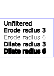
20 Filter primitive 'feOffset'
This filter primitive offsets the input image relative to its current
position in the image space by the specified vector.
This is important for effects like drop shadows.
When applying this filter, the destination location may be offset by a
fraction of a pixel in device space. In this case a high quality viewer
should make use of appropriate interpolation techniques, for example bilinear
or bicubic. This is especially recommended for dynamic viewers where this
interpolation provides visually smoother movement of images. For static
viewers this is less of a concern. Close attention should be made to the
'image-rendering' property setting to
determine the authors intent.
Attribute definitions:
- dx = "<number>"
- The amount to offset the input graphic along the x-axis. The offset
amount is expressed in the coordinate system established by attribute
primitiveUnits on the 'filter'
element.
If the attribute is not specified, then the effect is as if a value of
0 were specified.
Animatable:yes.
- dy = "<number>"
- The amount to offset the input graphic along the y-axis. The offset
amount is expressed in the coordinate system established by attribute
primitiveUnits on the 'filter'
element.
If the attribute is not specified, then the effect is as if a value of
0 were specified.
Animatable:yes.
The example at the start of this chapter makes
use of the feOffset filter primitive to
offset the drop shadow from the original source graphic.
21 Filter primitive 'feSpecularLighting'
This filter primitive lights a source graphic using the alpha channel as a
bump map. The resulting image is an RGBA image based on the light color. The
lighting calculation follows the standard specular component of the Phong
lighting model. The resulting image depends on the light color, light
position and surface geometry of the input bump map. The result of the
lighting calculation is added. The filter primitive assumes that the viewer
is at infinity in the z direction (i.e., the unit vector in the eye direction
is (0,0,1) everywhere).
This filter primitive produces an image which contains the specular
reflection part of the lighting calculation. Such a map is intended to be
combined with a texture using the add term of the
arithmetic 'feComposite' method. Multiple light sources
can be simulated by adding several of these light maps before applying it to
the texture image.
The resulting RGBA image is computed as follows:
Sr = ks * pow(N.H,
specularExponent) * Lr
Sg = ks * pow(N.H, specularExponent) *
Lg
Sb = ks * pow(N.H, specularExponent) *
Lb
Sa = max(Sr, Sg, Sb)
where
- ks = specular lighting constant
N = surface normal unit vector, a function of x and y
H = "halfway" unit vector between eye unit vector and light unit
vector
Lr,Lg,Lb = RGB components of light
See 'feDiffuseLighting' for definition of N and
(Lr, Lg, Lb).
The definition of H reflects our assumption of the constant eye vector E =
(0,0,1):
H = (L + E) / Norm(L+E)
where L is the light unit vector.
Unlike the 'feDiffuseLighting', the 'feSpecularLighting' filter produces a non-opaque
image. This is due to the fact that the specular result
(Sr,Sg,Sb,Sa) is meant to be
added to the textured image. The alpha channel of the result is the max of
the color components, so that where the specular light is zero, no additional
coverage is added to the image and a fully white highlight will add
opacity.
The 'feDiffuseLighting' and 'feSpecularLighting' filters will often be
applied together. An implementation may detect this and calculate both maps
in one pass, instead of two.
Attribute definitions:
- surfaceScale = "<number>"
- height of surface when Ain = 1.
If the attribute is not specified, then the effect is as if a value of
1 were specified.
Animatable:yes.
- specularConstant = "<number>"
- ks in Phong lighting model. In SVG, this can be any non-negative
number.
If the attribute is not specified, then the effect is as if a value of
1 were specified.
Animatable:yes.
- specularExponent = "<number>"
- Exponent for specular term, larger is more "shiny". Range 1.0 to
128.0.
If the attribute is not specified, then the effect is as if a value of
1 were specified.
Animatable:yes.
The light source is defined by one of the child elements 'feDistantLight', 'fePointLight' or 'feDistantLight'. The light color is
specified by property 'lighting-color'.
The example at the start of this chapter makes
use of the feSpecularLighting filter
primitive to achieve a highly reflective, 3D glowing effect.
22 Filter primitive 'feTile'
This filter primitive fills a target rectangle with a repeated, tiled
pattern of an input image.
Typically, the input image has been defined with its own filter primitive subregion in order to
define a reference tile. 'feTile'
replicates the reference tile in both X and Y to completely fill the target
rectangle. The top/left corner of each given tile is at location
(x+i*width,y+j*height), where (x,y) represents the
top/left of the input image's filter primitive subregion, width
and height represent the width and height of the input image's
filter primitive subregion, and i and j can be any
integer value. In most cases, the input image will have a smaller filter
primitive subregion than the 'feTile' in
order to achieve a repeated pattern effect.
Implementers must take appropriate measures in constructing the tiled
image to avoid artifacts between tiles, particularly in situations where the
user to device transform includes shear and/or rotation. Unless care is
taken, interpolation can lead to edge pixels in the tile having opacity
values lower or higher than expected due to the interaction of painting
adjacent tiles which each have partial overlap with particular pixels.
23 Filter primitive 'feTurbulence'
This filter primitive creates an image using the Perlin turbulence
function. It allows the synthesis of artificial textures like clouds or
marble. For a detailed description the of the Perlin turbulence function, see
"Texturing and Modeling", Ebert et al, AP Professional, 1994. The resulting
image will fill the entire filter
primitive subregion for this filter primitive.
It is possible to create bandwidth-limited noise by synthesizing only one
octave.
The C code below shows the exact algorithm used for this filter effect.
For fractalSum, you get a turbFunctionResult that is aimed at a range of
-1 to 1 (the actual result might exceed this range in some cases). To convert
to a color value, use the formula colorValue = ((turbFunctionResult *
255) + 255) / 2, then clamp to the range 0 to 255.
For turbulence, you get a turbFunctionResult that is aimed at a range of 0
to 1 (the actual result might exceed this range in some cases). To convert to
a color value, use the formula colorValue = (turbFunctionResult *
255), then clamp to the range 0 to 255.
The following order is used for applying the pseudo random numbers. An
initial seed value is computed based on attribute seed. Then the implementation computes the lattice
points for R, then continues getting additional pseudo random numbers
relative to the last generated pseudo random number and computes the lattice
points for G, and so on for B and A.
The generated color and alpha values are in the color space determined by
the value of property 'color-interpolation-filters':
/* Produces results in the range [1, 2**31 - 2].
Algorithm is: r = (a * r) mod m
where a = 16807 and m = 2**31 - 1 = 2147483647
See [Park & Miller], CACM vol. 31 no. 10 p. 1195, Oct. 1988
To test: the algorithm should produce the result 1043618065
as the 10,000th generated number if the original seed is 1.
*/
#define RAND_m 2147483647 /* 2**31 - 1 */
#define RAND_a 16807 /* 7**5; primitive root of m */
#define RAND_q 127773 /* m / a */
#define RAND_r 2836 /* m % a */
long setup_seed(long lSeed)
{
  if (lSeed <= 0) lSeed = -(lSeed % (RAND_m - 1)) + 1;
  if (lSeed > RAND_m - 1) lSeed = RAND_m - 1;
  return lSeed;
}
long random(long lSeed)
{
  long result;
  result = RAND_a * (lSeed % RAND_q) - RAND_r * (lSeed / RAND_q);
  if (result <= 0) result += RAND_m;
  return result;
}
#define BSize 0x100
#define BM 0xff
#define PerlinN 0x1000
#define NP 12 /* 2^PerlinN */
#define NM 0xfff
static uLatticeSelector[BSize + BSize + 2];
static double fGradient[4][BSize + BSize + 2][2];
struct StitchInfo
{
  int nWidth; // How much to subtract to wrap for stitching.
  int nHeight;
  int nWrapX; // Minimum value to wrap.
  int nWrapY;
};
static void init(long lSeed)
{
  double s;
  int i, j, k;
  lSeed = setup_seed(lSeed);
  for(k = 0; k < 4; k++)
  {
    for(i = 0; i < BSize; i++)
    {
      uLatticeSelector[i] = i;
      for (j = 0; j < 2; j++)
        fGradient[k][i][j] = (double)(((lSeed = random(lSeed)) % (BSize + BSize)) - BSize) / BSize;
      s = double(sqrt(fGradient[k][i][0] * fGradient[k][i][0] + fGradient[k][i][1] * fGradient[k][i][1]));
      fGradient[k][i][0] /= s;
      fGradient[k][i][1] /= s;
    }
  }
  while(--i)
  {
    k = uLatticeSelector[i];
    uLatticeSelector[i] = uLatticeSelector[j = (lSeed = random(lSeed)) % BSize];
    uLatticeSelector[j] = k;
  }
  for(i = 0; i < BSize + 2; i++)
  {
    uLatticeSelector[BSize + i] = uLatticeSelector[i];
    for(k = 0; k < 4; k++)
      for(j = 0; j < 2; j++)
        fGradient[k][BSize + i][j] = fGradient[k][i][j];
  }
}
#define s_curve(t) ( t * t * (3. - 2. * t) )
#define lerp(t, a, b) ( a + t * (b - a) )
double noise2(int nColorChannel, double vec[2], StitchInfo *pStitchInfo)
{
  int bx0, bx1, by0, by1, b00, b10, b01, b11;
  double rx0, rx1, ry0, ry1, *q, sx, sy, a, b, t, u, v;
  register i, j;
  t = vec[0] + PerlinN;
  bx0 = (int)t;
  bx1 = bx0+1;
  rx0 = t - (int)t;
  rx1 = rx0 - 1.0f;
  t = vec[1] + PerlinN;
  by0 = (int)t;
  by1 = by0+1;
  ry0 = t - (int)t;
  ry1 = ry0 - 1.0f;
  // If stitching, adjust lattice points accordingly.
  if(pStitchInfo != NULL)
  {
    if(bx0 >= pStitchInfo->nWrapX)
      bx0 -= pStitchInfo->nWidth;
    if(bx1 >= pStitchInfo->nWrapX)
      bx1 -= pStitchInfo->nWidth;
    if(by0 >= pStitchInfo->nWrapY)
      by0 -= pStitchInfo->nHeight;
    if(by1 >= pStitchInfo->nWrapY)
      by1 -= pStitchInfo->nHeight;
  }
  bx0 &= BM;
  bx1 &= BM;
  by0 &= BM;
  by1 &= BM;
  i = uLatticeSelector[bx0];
  j = uLatticeSelector[bx1];
  b00 = uLatticeSelector[i + by0];
  b10 = uLatticeSelector[j + by0];
  b01 = uLatticeSelector[i + by1];
  b11 = uLatticeSelector[j + by1];
  sx = double(s_curve(rx0));
  sy = double(s_curve(ry0));
  q = fGradient[nColorChannel][b00]; u = rx0 * q[0] + ry0 * q[1];
  q = fGradient[nColorChannel][b10]; v = rx1 * q[0] + ry0 * q[1];
  a = lerp(sx, u, v);
  q = fGradient[nColorChannel][b01]; u = rx0 * q[0] + ry1 * q[1];
  q = fGradient[nColorChannel][b11]; v = rx1 * q[0] + ry1 * q[1];
  b = lerp(sx, u, v);
  return lerp(sy, a, b);
}
double turbulence(int nColorChannel, double *point, double fBaseFreqX, double fBaseFreqY,
          int nNumOctaves, bool bFractalSum, bool bDoStitching,
          double fTileX, double fTileY, double fTileWidth, double fTileHeight)
{
  StitchInfo stitch;
  StitchInfo *pStitchInfo = NULL; // Not stitching when NULL.
  // Adjust the base frequencies if necessary for stitching.
  if(bDoStitching)
  {
    // When stitching tiled turbulence, the frequencies must be adjusted
    // so that the tile borders will be continuous.
    if(fBaseFreqX != 0.0)
    {
      double fLoFreq = double(floor(fTileWidth * fBaseFreqX)) / fTileWidth;
      double fHiFreq = double(ceil(fTileWidth * fBaseFreqX)) / fTileWidth;
      if(fBaseFreqX / fLoFreq < fHiFreq / fBaseFreqX)
        fBaseFreqX = fLoFreq;
      else
        fBaseFreqX = fHiFreq;
    }
    if(fBaseFreqY != 0.0)
    {
      double fLoFreq = double(floor(fTileHeight * fBaseFreqY)) / fTileHeight;
      double fHiFreq = double(ceil(fTileHeight * fBaseFreqY)) / fTileHeight;
      if(fBaseFreqY / fLoFreq < fHiFreq / fBaseFreqY)
        fBaseFreqY = fLoFreq;
      else
        fBaseFreqY = fHiFreq;
    }
    // Set up initial stitch values.
    pStitchInfo = &stitch;
    stitch.nWidth = int(fTileWidth * fBaseFreqX + 0.5f);
    stitch.nWrapX = fTileX * fBaseFreqX + PerlinN + stitch.nWidth;
    stitch.nHeight = int(fTileHeight * fBaseFreqY + 0.5f);
    stitch.nWrapY = fTileY * fBaseFreqY + PerlinN + stitch.nHeight;
  }
  double fSum = 0.0f;
  double vec[2];
  vec[0] = point[0] * fBaseFreqX;
  vec[1] = point[1] * fBaseFreqY;
  double ratio = 1;
  for(int nOctave = 0; nOctave < nNumOctaves; nOctave++)
  {
    if(bFractalSum)
      fSum += double(noise2(nColorChannel, vec, pStitchInfo) / ratio);
    else
      fSum += double(fabs(noise2(nColorChannel, vec, pStitchInfo)) / ratio);
    vec[0] *= 2;
    vec[1] *= 2;
    ratio *= 2;
    if(pStitchInfo != NULL)
    {
      // Update stitch values. Subtracting PerlinN before the multiplication and
      // adding it afterward simplifies to subtracting it once.
      stitch.nWidth *= 2;
      stitch.nWrapX = 2 * stitch.nWrapX - PerlinN;
      stitch.nHeight *= 2;
      stitch.nWrapY = 2 * stitch.nWrapY - PerlinN;
    }
  }
  return fSum;
}
Attribute definitions:
- baseFrequency =
"<number-optional-number>"
- The base frequency (frequencies) parameter(s) for the noise function.
If two <number>
s are provided, the first number represents a base frequency in the X
direction and the second value represents a base frequency in the Y
direction. If one number is provided, then that value is used for both
X and Y.
If the attribute is not specified, or if a negative value for base
frequency is specified, then the effect is as if a value of 0 were specified.
Animatable:yes.
- numOctaves = "<integer>"
- The numOctaves parameter for the noise function.
If the attribute is not specified, then the effect is as if a value of
1 were specified.
Animatable:yes.
-
seed = "<number>"
- The starting number for the pseudo random number generator.
If the attribute is not specified, then the effect is as if a value of
0 were specified.
Animatable:yes.
- stitchTiles = "stitch | noStitch"
- If stitchTiles="noStitch", no attempt
it made to achieve smooth transitions at the border of tiles which
contain a turbulence function. Sometimes the result will show clear
discontinuities at the tile borders.
If stitchTiles="stitch", then the user
agent will automatically adjust baseFrequency-x and baseFrequency-y
values such that the feTurbulence node's width and height (i.e., the
width and height of the current subregion) contains an integral number
of the Perlin tile width and height for the first octave. The
baseFrequency will be adjusted up or down depending on which way has
the smallest relative (not absolute) change as follows: Given the
frequency, calculate lowFreq=floor(width*frequency)/width
and hiFreq=ceil(width*frequency)/width. If
frequency/lowFreq < hiFreq/frequency then use lowFreq, else use
hiFreq. While generating turbulence values, generate lattice vectors as
normal for Perlin Noise, except for those lattice points that lie on
the right or bottom edges of the active area (the size of the resulting
tile). In those cases, copy the lattice vector from the opposite edge
of the active area.
Animatable:yes.
-
type = "fractalNoise | turbulence"
- Indicates whether the filter primitive should perform a noise or
turbulence function.
Animatable:yes.
<?xml version="1.0"?>
<!DOCTYPE svg PUBLIC "-//W3C//DTD SVG 1.1//EN"
          "http://www.w3.org/Graphics/SVG/1.1/DTD/svg11.dtd">
<svg width="450px" height="325px" viewBox="0 0 450 325"
     xmlns="http://www.w3.org/2000/svg" version="1.1">
  <title>Example feTurbulence - Examples of feTurbulence operations</title>
  <desc>Six rectangular areas showing the effects of
        various parameter settings for feTurbulence.</desc>
  <g  font-family="Verdana" text-anchor="middle" font-size="10" >
    <defs>
      <filter id="Turb1" filterUnits="objectBoundingBox"
              x="0%" y="0%" width="100%" height="100%">
        <feTurbulence type="turbulence" baseFrequency="0.05" numOctaves="2"/>
      </filter>
      <filter id="Turb2" filterUnits="objectBoundingBox"
              x="0%" y="0%" width="100%" height="100%">
        <feTurbulence type="turbulence" baseFrequency="0.1" numOctaves="2"/>
      </filter>
      <filter id="Turb3" filterUnits="objectBoundingBox"
              x="0%" y="0%" width="100%" height="100%">
        <feTurbulence type="turbulence" baseFrequency="0.05" numOctaves="8"/>
      </filter>
      <filter id="Turb4" filterUnits="objectBoundingBox"
              x="0%" y="0%" width="100%" height="100%">
        <feTurbulence type="fractalNoise" baseFrequency="0.1" numOctaves="4"/>
      </filter>
      <filter id="Turb5" filterUnits="objectBoundingBox"
              x="0%" y="0%" width="100%" height="100%">
        <feTurbulence type="fractalNoise" baseFrequency="0.4" numOctaves="4"/>
      </filter>
      <filter id="Turb6" filterUnits="objectBoundingBox"
              x="0%" y="0%" width="100%" height="100%">
        <feTurbulence type="fractalNoise" baseFrequency="0.1" numOctaves="1"/>
      </filter>
    </defs>

    <rect x="1" y="1" width="448" height="323"
          fill="none" stroke="blue" stroke-width="1"  />

    <rect x="25" y="25" width="100" height="75" filter="url(#Turb1)"  />
    <text x="75" y="117">type=turbulence</text>
    <text x="75" y="129">baseFrequency=0.05</text>
    <text x="75" y="141">numOctaves=2</text>

    <rect x="175" y="25" width="100" height="75" filter="url(#Turb2)"  />
    <text x="225" y="117">type=turbulence</text>
    <text x="225" y="129">baseFrequency=0.1</text>
    <text x="225" y="141">numOctaves=2</text>

    <rect x="325" y="25" width="100" height="75" filter="url(#Turb3)"  />
    <text x="375" y="117">type=turbulence</text>
    <text x="375" y="129">baseFrequency=0.05</text>
    <text x="375" y="141">numOctaves=8</text>

    <rect x="25" y="180" width="100" height="75" filter="url(#Turb4)"  />
    <text x="75" y="272">type=fractalNoise</text>
    <text x="75" y="284">baseFrequency=0.1</text>
    <text x="75" y="296">numOctaves=4</text>

    <rect x="175" y="180" width="100" height="75" filter="url(#Turb5)"  />
    <text x="225" y="272">type=fractalNoise</text>
    <text x="225" y="284">baseFrequency=0.4</text>
    <text x="225" y="296">numOctaves=4</text>

    <rect x="325" y="180" width="100" height="75" filter="url(#Turb6)"  />
    <text x="375" y="272">type=fractalNoise</text>
    <text x="375" y="284">baseFrequency=0.1</text>
    <text x="375" y="296">numOctaves=1</text>
  </g>
</svg>
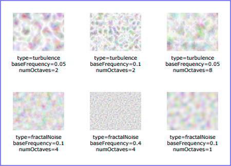
24 Filter primitive 'feDropShadow'
This filter creates a drop shadow of the input image. It is a shorthand
filter, and is defined in terms of combinations of other filter primitives.
The expectation is that it can be optimized more easily by
implementations.
The result of a 'feDropShadow' filter
primitive is equivalent to the following:
  <feGaussianBlur in="alpha-channel-of-feDropShadow-in" stdDeviation="stdDeviation-of-feDropShadow"/>
  <feOffset dx="dx-of-feDropShadow" dy="dy-of-feDropShadow" result="offsetblur"/>
  <feFlood flood-color="flood-color-of-feDropShadow" flood-opacity="flood-opacity-of-feDropShadow"/>
  <feComposite in2="offsetblur" operator="in"/>
  <feMerge>
    <feMergeNode/>
    <feMergeNode in="in-of-feDropShadow"/>
  </feMerge>
The above divided into steps:
- Take the alpha channel of the input to the 'feDropShadow' filter primitive and the stdDeviation on the 'feDropShadow' and do processing as if the
following 'feGaussianBlur' was applied:
<feGaussianBlur in="alpha-channel-of-feDropShadow-in" stdDeviation="stdDeviation-of-feDropShadow"/>
- Offset the result of step 1 by dx and dy as
specified on the 'feDropShadow'
element, equivalent to applying an 'feOffset' with these parameters:
<feOffset dx="dx-of-feDropShadow" dy="dy-of-feDropShadow" result="offsetblur"/>
- Do processing as if an 'feFlood' element with 'flood-color' and 'flood-opacity' as specified on the 'feDropShadow' was applied:
<feFlood flood-color="flood-color-of-feDropShadow" flood-opacity="flood-opacity-of-feDropShadow"/>
- Composite the result of the 'feFlood' in step 3 with the result of
the 'feOffset' in step 2 as if an 'feComposite' filter primitive with operator='in' was applied:
<feComposite in2="offsetblur" operator="in"/>
- Finally merge the result of the previous step, doing processing as if
the following 'feMerge' was performed:
	<feMerge>
	    <feMergeNode/>
	    <feMergeNode in="in-of-feDropShadow"/>
	</feMerge>
Note that while the definition of the 'feDropShadow' filter primitive says that it can
be expanded into an equivalent tree it is not required that it is implemented
like that. The expectation is that user agents can optimize the handling by not having to do all the steps separately. Beyond the DOM interface SVGFEDropShadow there is no way
of accessing the internals of the 'feDropShadow' filter primitive, meaning if the
filter primitive is implemented as an equivalent tree then that tree must not
be exposed to the DOM.
Attribute definitions:
-
dx = "<number>"
- The x offset of the drop shadow. If the attribute is not specified,
then the effect is as if a value of 2
were specified. This attribute is then forwarded to the dx attribute of the internal 'feOffset' element.
Animatable:yes.
-
dy = "<number>"
- The y offset of the drop shadow. If the attribute is not specified,
then the effect is as if a value of 2
were specified. This attribute is then forwarded to the dy attribute of the internal 'feOffset' element.
Animatable:yes.
- stdDeviation =
"<number-optional-number>"
- The standard deviation for the blur operation in the drop shadow. If
the attribute is not specified, then the effect is as if a value of
2 were specified. This attribute is
then forwarded to the stdDeviation attribute of the internal 'feGaussianBlur' element.
Animatable:yes.
25 Filter primitive 'feDiffuseSpecular'
The SVG WG is looking at providing a shorthand for diffuse+specular.
26 Filter primitive 'feCustom'
The SVG WG is looking to add a filter primitive that allows programmatic access
to the pixel data for a filter.
27 RelaxNG Schema for SVG Filters 1.2
The schema for SVG Filters 1.2 is written in RelaxNG
[RelaxNG], a namespace-aware schema language that uses
the datatypes from XML Schema Part
2 [Schema2]. This allows namespaces and
modularity to be much more naturally expressed than using DTD syntax. The
RelaxNG schema for SVG Filter 1.2 may be imported by other RelaxNG schemas,
or combined with other schemas in other languages into a multi-namespace,
multi-grammar schema using Namespace-based Validation
Dispatching Language [NVDL].
Unlike a DTD, the schema used for validation is not hardcoded into the
document instance. There is no equivalent to the DOCTYPE declaration. Simply
point your editor or other validation tool to the IRI of the schema (or your
local cached copy, as you prefer).
The RNG is under construction, and only the individual RNG snippets are available at this time. They have not yet been integrated into a functional schema. The individual RNG files are available here.
28 DOM interfaces
The interfaces below will be made available in a IDL file for an upcoming draft.
The following interfaces are defined below: ImageData, SVGFilterElement, SVGFilterPrimitiveStandardAttributes,
SVGFEBlendElement, SVGFEColorMatrixElement, SVGFEComponentTransferElement,
SVGComponentTransferFunctionElement,
SVGFEFuncRElement, SVGFEFuncGElement, SVGFEFuncBElement, SVGFEFuncAElement, SVGFECompositeElement, SVGFEConvolveMatrixElement,
SVGFEDiffuseLightingElement,
SVGFEDistantLightElement, SVGFEPointLightElement, SVGFESpotLightElement, SVGFEDisplacementMapElement,
SVGFEFloodElement, SVGFEGaussianBlurElement, SVGFEImageElement, SVGFEMergeElement, SVGFEMergeNodeElement, SVGFEMorphologyElement, SVGFEOffsetElement, SVGFESpecularLightingElement,
SVGFETileElement, SVGFETurbulenceElement, SVGFEDropShadowElement.
28.1 Interface ImageData
The ImageData interface corresponds
to pixel data that can be used as input to the SVGFilterElement interface.
IDL Definition-
interface ImageData {
  readonly attribute unsigned long width;
  readonly attribute unsigned long height;
  readonly attribute int[] data;
};
- Attributes
- readonly unsigned long width
- The width of the bitmap that the ImageData represents.
- readonly unsigned long height
- The height of the bitmap that the ImageData represents.
- readonly int[] data
- An array of pixel values that is the bitmap. This array must
always be in the form of width×height×4 integer values. The
pixel data is in left-to-right order, starting from the top-left
corner, and going row by row downwards. Every pixel is
represented by four integer values, red, green, blue and alpha,
in that order. The range of each color component is 0..255. The
intent is that this is compatible with WHATWG [WHATWG] canvas interfaces, in particular
see ImageData.
28.2 Interface SVGFilterElement
The SVGFilterElement interface
corresponds to the 'filter' element.
IDL Definition-
interface SVGFilterElement :
                SVGElement,
                SVGURIReference,
                SVGLangSpace,
                SVGExternalResourcesRequired,
                SVGStylable,
                SVGUnitTypes {
  readonly attribute SVGAnimatedEnumeration filterUnits;
  readonly attribute SVGAnimatedEnumeration primitiveUnits;
  readonly attribute SVGAnimatedEnumeration filterMarginUnits;
  readonly attribute SVGAnimatedEnumeration primitiveMarginUnits;
  readonly attribute SVGAnimatedLength      x;
  readonly attribute SVGAnimatedLength      y;
  readonly attribute SVGAnimatedLength      width;
  readonly attribute SVGAnimatedLength      height;
  readonly attribute SVGAnimatedInteger     filterResX;
  readonly attribute SVGAnimatedInteger     filterResY;
  void setFilterRes ( in unsigned long filterResX, in unsigned long filterResY );
  ImageData apply(in ImageData source);
};
- Attributes
- readonly SVGAnimatedEnumeration filterUnits
- Corresponds to attribute filterUnits on the given 'filter' element. Takes one of the
constants defined in SVGUnitTypes.
- readonly SVGAnimatedEnumeration primitiveUnits
- Corresponds to attribute primitiveUnits on the given 'filter' element. Takes one of the
constants defined in SVGUnitTypes.
- readonly SVGAnimatedEnumeration filterMarginUnits
- Corresponds to attribute filterMarginUnits on the given 'filter' element. Takes one of the
constants defined in SVGUnitTypes.
- readonly SVGAnimatedEnumeration primitiveMarginUnits
- Corresponds to attribute primitiveMarginUnits on the given 'filter' element. Takes one of the
constants defined in SVGUnitTypes.
- readonly SVGAnimatedLength x
- Corresponds to attribute x on
the given 'filter' element.
- readonly SVGAnimatedLength y
- Corresponds to attribute y on
the given 'filter' element.
- readonly SVGAnimatedLength width
- Corresponds to attribute width
on the given 'filter'
element.
- readonly SVGAnimatedLength height
- Corresponds to attribute height
on the given 'filter'
element.
- readonly SVGAnimatedInteger filterResX
- Corresponds to attribute filterRes on the given 'filter' element. Contains the X
component of attribute filterRes.
- readonly SVGAnimatedInteger filterResY
- Corresponds to attribute filterRes on the given 'filter' element. Contains the Y
component (possibly computed automatically) of attribute filterRes.
- Methods
- setFilterRes
- Sets the values for attribute filterRes.
- Parameters
-
| in unsigned long
filterResX |
|
The X component of attribute filterRes. |
| in unsigned long
filterResY |
|
The Y component of attribute filterRes. |
- No Return Value
- No Exceptions
- apply
- Applies the filter to the given ImageData object and returns
the result.
- Parameters
-
| in ImageData source |
|
The image to apply the filter to. |
- Return value
-
| ImageData |
|
The result of the filter, see ImageData for how to
construct this. |
- No Exceptions
28.3 Interface SVGFilterPrimitiveStandardAttributes
This interface defines the set of DOM attributes that are common across
the filter interfaces.
IDL Definition-
interface SVGFilterPrimitiveStandardAttributes : SVGStylable {
  readonly attribute SVGAnimatedLength x;
  readonly attribute SVGAnimatedLength y;
  readonly attribute SVGAnimatedLength width;
  readonly attribute SVGAnimatedLength height;
  readonly attribute SVGAnimatedString result;
};
- Attributes
- readonly SVGAnimatedLength x
- Corresponds to attribute x on
the given element.
- readonly SVGAnimatedLength y
- Corresponds to attribute y on
the given element.
- readonly SVGAnimatedLength width
- Corresponds to attribute width
on the given element.
- readonly SVGAnimatedLength height
- Corresponds to attribute height
on the given element.
- readonly SVGAnimatedString result
- Corresponds to attribute result
on the given element.
28.4 Interface SVGFEBlendElement
The SVGFEBlendElement interface
corresponds to the 'feBlend' element.
IDL Definition-
interface SVGFEBlendElement :
                SVGElement,
                SVGFilterPrimitiveStandardAttributes {
  // Blend Mode Types
  const unsigned short SVG_FEBLEND_MODE_UNKNOWN  = 0;
  const unsigned short SVG_FEBLEND_MODE_NORMAL   = 1;
  const unsigned short SVG_FEBLEND_MODE_MULTIPLY = 2;
  const unsigned short SVG_FEBLEND_MODE_SCREEN   = 3;
  const unsigned short SVG_FEBLEND_MODE_DARKEN   = 4;
  const unsigned short SVG_FEBLEND_MODE_LIGHTEN  = 5;
  readonly attribute SVGAnimatedString      in1;
  readonly attribute SVGAnimatedString      in2;
  readonly attribute SVGAnimatedEnumeration mode;
};
- Definition group Blend Mode Types
- Defined constants
-
| SVG_FEBLEND_MODE_UNKNOWN |
|
The type is not one of predefined types.
It is invalid to attempt to define a new value of this
type or to attempt to switch an existing value to this
type. |
| SVG_FEBLEND_MODE_NORMAL |
|
Corresponds to value normal. |
| SVG_FEBLEND_MODE_MULTIPLY |
|
Corresponds to value multiply. |
| SVG_FEBLEND_MODE_SCREEN |
|
Corresponds to value screen. |
| SVG_FEBLEND_MODE_DARKEN |
|
Corresponds to value darken. |
| SVG_FEBLEND_MODE_LIGHTEN |
|
Corresponds to value lighten. |
- Attributes
- readonly SVGAnimatedString in1
- Corresponds to attribute in on
the given 'feBlend'
element.
- readonly SVGAnimatedString in2
- Corresponds to attribute in2 on
the given 'feBlend'
element.
- readonly SVGAnimatedEnumeration mode
- Corresponds to attribute mode on
the given 'feBlend' element.
Takes one of the Blend Mode Types.
28.5 Interface SVGFEColorMatrixElement
The SVGFEColorMatrixElement
interface corresponds to the 'feColorMatrix' element.
IDL Definition-
interface SVGFEColorMatrixElement :
                SVGElement,
                SVGFilterPrimitiveStandardAttributes {
  // Color Matrix Types
  const unsigned short SVG_FECOLORMATRIX_TYPE_UNKNOWN          = 0;
  const unsigned short SVG_FECOLORMATRIX_TYPE_MATRIX           = 1;
  const unsigned short SVG_FECOLORMATRIX_TYPE_SATURATE         = 2;
  const unsigned short SVG_FECOLORMATRIX_TYPE_HUEROTATE        = 3;
  const unsigned short SVG_FECOLORMATRIX_TYPE_LUMINANCETOALPHA = 4;
  readonly attribute SVGAnimatedString      in1;
  readonly attribute SVGAnimatedEnumeration type;
  readonly attribute SVGAnimatedNumberList  values;
};
- Definition group Color Matrix Types
- Defined constants
-
| SVG_FECOLORMATRIX_TYPE_UNKNOWN |
|
The type is not one of predefined types.
It is invalid to attempt to define a new value of this
type or to attempt to switch an existing value to this
type. |
| SVG_FECOLORMATRIX_TYPE_MATRIX |
|
Corresponds to value matrix. |
| SVG_FECOLORMATRIX_TYPE_SATURATE |
|
Corresponds to value saturate. |
| SVG_FECOLORMATRIX_TYPE_HUEROTATE |
|
Corresponds to value hueRotate. |
| SVG_FECOLORMATRIX_TYPE_LUMINANCETOALPHA |
|
Corresponds to value luminanceToAlpha. |
- Attributes
- readonly SVGAnimatedString in1
- Corresponds to attribute in on
the given 'feColorMatrix'
element.
- readonly SVGAnimatedEnumeration type
- Corresponds to attribute type on
the given 'feColorMatrix'
element. Takes one of the Color Matrix Types.
- readonly SVGAnimatedNumberList values
- Corresponds to attribute values
on the given 'feColorMatrix'
element.
Provides access to the contents of the values attribute.
28.6 Interface SVGFEComponentTransferElement
The SVGFEComponentTransferElement
interface corresponds to the 'feComponentTransfer' element.
IDL Definition-
interface SVGFEComponentTransferElement :
                SVGElement,
                SVGFilterPrimitiveStandardAttributes {
  readonly attribute SVGAnimatedString in1;
};
- Attributes
- readonly SVGAnimatedString in1
- Corresponds to attribute in on
the given 'feComponentTransfer'
element.
28.7 Interface SVGComponentTransferFunctionElement
This interface defines a base interface used by the component transfer
function interfaces.
IDL Definition-
interface SVGComponentTransferFunctionElement : SVGElement {
  // Component Transfer Types
  const unsigned short SVG_FECOMPONENTTRANSFER_TYPE_UNKNOWN  = 0;
  const unsigned short SVG_FECOMPONENTTRANSFER_TYPE_IDENTITY = 1;
  const unsigned short SVG_FECOMPONENTTRANSFER_TYPE_TABLE    = 2;
  const unsigned short SVG_FECOMPONENTTRANSFER_TYPE_DISCRETE    = 3;
  const unsigned short SVG_FECOMPONENTTRANSFER_TYPE_LINEAR   = 4;
  const unsigned short SVG_FECOMPONENTTRANSFER_TYPE_GAMMA    = 5;
  readonly attribute SVGAnimatedEnumeration type;
  readonly attribute SVGAnimatedNumberList  tableValues;
  readonly attribute SVGAnimatedNumber      slope;
  readonly attribute SVGAnimatedNumber      intercept;
  readonly attribute SVGAnimatedNumber      amplitude;
  readonly attribute SVGAnimatedNumber      exponent;
  readonly attribute SVGAnimatedNumber      offset;
};
- Definition group Component Transfer Types
- Defined constants
-
| SVG_FECOMPONENTTRANSFER_TYPE_UNKNOWN |
|
The type is not one of predefined types.
It is invalid to attempt to define a new value of this
type or to attempt to switch an existing value to this
type. |
| SVG_FECOMPONENTTRANSFER_TYPE_IDENTITY |
|
Corresponds to value identity. |
| SVG_FECOMPONENTTRANSFER_TYPE_TABLE |
|
Corresponds to value table. |
| SVG_FECOMPONENTTRANSFER_TYPE_DISCRETE |
|
Corresponds to value discrete. |
| SVG_FECOMPONENTTRANSFER_TYPE_LINEAR |
|
Corresponds to value linear. |
| SVG_FECOMPONENTTRANSFER_TYPE_GAMMA |
|
Corresponds to value gamma. |
- Attributes
- readonly SVGAnimatedEnumeration type
- Corresponds to attribute type on
the given element. Takes one of the Component Transfer Types.
- readonly SVGAnimatedNumberList tableValues
- Corresponds to attribute tableValues on the given element.
- readonly SVGAnimatedNumber slope
- Corresponds to attribute slope
on the given element.
- readonly SVGAnimatedNumber intercept
- Corresponds to attribute intercept on the given element.
- readonly SVGAnimatedNumber amplitude
- Corresponds to attribute amplitude on the given element.
- readonly SVGAnimatedNumber exponent
- Corresponds to attribute exponent on the given element.
- readonly SVGAnimatedNumber offset
- Corresponds to attribute offset
on the given element.
28.8 Interface SVGFEFuncRElement
The SVGFEFuncRElement interface
corresponds to the 'feFuncR' element.
IDL Definition-
interface SVGFEFuncRElement : SVGComponentTransferFunctionElement {};
28.9 Interface SVGFEFuncGElement
The SVGFEFuncGElement interface
corresponds to the 'feFuncG' element.
IDL Definition-
interface SVGFEFuncGElement : SVGComponentTransferFunctionElement {};
28.10 Interface SVGFEFuncBElement
The SVGFEFuncBElement interface
corresponds to the 'feFuncB' element.
IDL Definition-
interface SVGFEFuncBElement : SVGComponentTransferFunctionElement {};
28.11 Interface SVGFEFuncAElement
The SVGFEFuncAElement interface
corresponds to the 'feFuncA' element.
IDL Definition-
interface SVGFEFuncAElement : SVGComponentTransferFunctionElement {};
28.12 Interface SVGFECompositeElement
The SVGFECompositeElement interface
corresponds to the 'feComposite'
element.
IDL Definition-
interface SVGFECompositeElement :
                SVGElement,
                SVGFilterPrimitiveStandardAttributes {
  // Composite Operators
  const unsigned short SVG_FECOMPOSITE_OPERATOR_UNKNOWN    = 0;
  const unsigned short SVG_FECOMPOSITE_OPERATOR_OVER       = 1;
  const unsigned short SVG_FECOMPOSITE_OPERATOR_IN         = 2;
  const unsigned short SVG_FECOMPOSITE_OPERATOR_OUT        = 3;
  const unsigned short SVG_FECOMPOSITE_OPERATOR_ATOP       = 4;
  const unsigned short SVG_FECOMPOSITE_OPERATOR_XOR        = 5;
  const unsigned short SVG_FECOMPOSITE_OPERATOR_ARITHMETIC = 6;
  readonly attribute SVGAnimatedString      in1;
  readonly attribute SVGAnimatedString      in2;
  readonly attribute SVGAnimatedEnumeration operator;
  readonly attribute SVGAnimatedNumber      k1;
  readonly attribute SVGAnimatedNumber      k2;
  readonly attribute SVGAnimatedNumber      k3;
  readonly attribute SVGAnimatedNumber      k4;
};
- Definition group Composite Operators
- Defined constants
-
| SVG_FECOMPOSITE_OPERATOR_UNKNOWN |
|
The type is not one of predefined types.
It is invalid to attempt to define a new value of this
type or to attempt to switch an existing value to this
type. |
| SVG_FECOMPOSITE_OPERATOR_OVER |
|
Corresponds to value over. |
| SVG_FECOMPOSITE_OPERATOR_IN |
|
Corresponds to value in. |
| SVG_FECOMPOSITE_OPERATOR_OUT |
|
Corresponds to value out. |
| SVG_FECOMPOSITE_OPERATOR_ATOP |
|
Corresponds to value atop. |
| SVG_FECOMPOSITE_OPERATOR_XOR |
|
Corresponds to value xor. |
| SVG_FECOMPOSITE_OPERATOR_ARITHMETIC |
|
Corresponds to value arithmetic. |
- Attributes
- readonly SVGAnimatedString in1
- Corresponds to attribute in on
the given 'feComposite'
element.
- readonly SVGAnimatedString in2
- Corresponds to attribute in2 on
the given 'feComposite'
element.
- readonly SVGAnimatedEnumeration operator
- Corresponds to attribute operator on the given 'feComposite' element. Takes one of
the Composite Operators.
- readonly SVGAnimatedNumber k1
- Corresponds to attribute k1 on
the given 'feComposite'
element.
- readonly SVGAnimatedNumber k2
- Corresponds to attribute k2 on
the given 'feComposite'
element.
- readonly SVGAnimatedNumber k3
- Corresponds to attribute k3 on
the given 'feComposite'
element.
- readonly SVGAnimatedNumber k4
- Corresponds to attribute k4 on
the given 'feComposite'
element.
28.13 Interface SVGFEConvolveMatrixElement
The SVGFEConvolveMatrixElement
interface corresponds to the 'feConvolveMatrix' element.
IDL Definition-
interface SVGFEConvolveMatrixElement :
                SVGElement,
                SVGFilterPrimitiveStandardAttributes {
  // Edge Mode Values
  const unsigned short SVG_EDGEMODE_UNKNOWN   = 0;
  const unsigned short SVG_EDGEMODE_DUPLICATE = 1;
  const unsigned short SVG_EDGEMODE_WRAP      = 2;
  const unsigned short SVG_EDGEMODE_NONE      = 3;
  readonly attribute SVGAnimatedString      in1;
  readonly attribute SVGAnimatedInteger     orderX;
  readonly attribute SVGAnimatedInteger     orderY;
  readonly attribute SVGAnimatedNumberList  kernelMatrix;
  readonly attribute SVGAnimatedNumber      divisor;
  readonly attribute SVGAnimatedNumber      bias;
  readonly attribute SVGAnimatedInteger     targetX;
  readonly attribute SVGAnimatedInteger     targetY;
  readonly attribute SVGAnimatedEnumeration edgeMode;
  readonly attribute SVGAnimatedNumber      kernelUnitLengthX;
  readonly attribute SVGAnimatedNumber      kernelUnitLengthY;
  readonly attribute SVGAnimatedBoolean     preserveAlpha;
};
- Definition group Edge Mode Values
- Defined constants
-
| SVG_EDGEMODE_UNKNOWN |
|
The type is not one of predefined types.
It is invalid to attempt to define a new value of this
type or to attempt to switch an existing value to this
type. |
| SVG_EDGEMODE_DUPLICATE |
|
Corresponds to value duplicate. |
| SVG_EDGEMODE_WRAP |
|
Corresponds to value wrap. |
| SVG_EDGEMODE_NONE |
|
Corresponds to value none. |
- Attributes
- readonly SVGAnimatedString in1
- Corresponds to attribute in on
the given 'feConvolveMatrix'
element.
- readonly SVGAnimatedInteger orderX
- Corresponds to attribute order
on the given 'feConvolveMatrix'
element.
- readonly SVGAnimatedInteger orderY
- Corresponds to attribute order
on the given 'feConvolveMatrix'
element.
- readonly SVGAnimatedNumberList kernelMatrix
- Corresponds to attribute kernelMatrix on the given element.
- readonly SVGAnimatedNumber divisor
- Corresponds to attribute divisor
on the given 'feConvolveMatrix'
element.
- readonly SVGAnimatedNumber bias
- Corresponds to attribute bias on
the given 'feConvolveMatrix'
element.
- readonly SVGAnimatedInteger targetX
- Corresponds to attribute targetX
on the given 'feConvolveMatrix'
element.
- readonly SVGAnimatedInteger targetY
- Corresponds to attribute targetY
on the given 'feConvolveMatrix'
element.
- readonly SVGAnimatedEnumeration edgeMode
- Corresponds to attribute edgeMode on the given 'feConvolveMatrix' element. Takes one
of the Edge Mode Types.
- readonly SVGAnimatedNumber kernelUnitLengthX
- Corresponds to attribute kernelUnitLength on the given 'feConvolveMatrix' element.
- readonly SVGAnimatedNumber kernelUnitLengthY
- Corresponds to attribute kernelUnitLength on the given 'feConvolveMatrix' element.
- readonly SVGAnimatedBoolean preserveAlpha
- Corresponds to attribute preserveAlpha on the given 'feConvolveMatrix' element.
28.14 Interface SVGFEDiffuseLightingElement
The SVGFEDiffuseLightingElement
interface corresponds to the 'feDiffuseLighting' element.
IDL Definition-
interface SVGFEDiffuseLightingElement :
                SVGElement,
                SVGFilterPrimitiveStandardAttributes {
  readonly attribute SVGAnimatedString in1;
  readonly attribute SVGAnimatedNumber surfaceScale;
  readonly attribute SVGAnimatedNumber diffuseConstant;
  readonly attribute SVGAnimatedNumber kernelUnitLengthX;
  readonly attribute SVGAnimatedNumber kernelUnitLengthY;
};
- Attributes
- readonly SVGAnimatedString in1
- Corresponds to attribute in on
the given 'feDiffuseLighting'
element.
- readonly SVGAnimatedNumber surfaceScale
- Corresponds to attribute surfaceScale on the given 'feDiffuseLighting' element.
- readonly SVGAnimatedNumber diffuseConstant
- Corresponds to attribute diffuseConstant on the given 'feDiffuseLighting' element.
- readonly SVGAnimatedNumber kernelUnitLengthX
- Corresponds to attribute kernelUnitLength on the given 'feDiffuseLighting' element.
- readonly SVGAnimatedNumber kernelUnitLengthY
- Corresponds to attribute kernelUnitLength on the given 'feDiffuseLighting' element.
28.15 Interface SVGFEDistantLightElement
The SVGFEDistantLightElement
interface corresponds to the 'feDistantLight' element.
IDL Definition-
interface SVGFEDistantLightElement : SVGElement {
  readonly attribute SVGAnimatedNumber azimuth;
  readonly attribute SVGAnimatedNumber elevation;
};
- Attributes
- readonly SVGAnimatedNumber azimuth
- Corresponds to attribute azimuth
on the given 'feDistantLight'
element.
- readonly SVGAnimatedNumber elevation
- Corresponds to attribute elevation on the given 'feDistantLight' element.
28.16 Interface SVGFEPointLightElement
The SVGFEPointLightElement interface
corresponds to the 'fePointLight'
element.
IDL Definition-
interface SVGFEPointLightElement : SVGElement {
  readonly attribute SVGAnimatedNumber x;
  readonly attribute SVGAnimatedNumber y;
  readonly attribute SVGAnimatedNumber z;
};
- Attributes
- readonly SVGAnimatedNumber x
- Corresponds to attribute x on
the given 'fePointLight'
element.
- readonly SVGAnimatedNumber y
- Corresponds to attribute y on
the given 'fePointLight'
element.
- readonly SVGAnimatedNumber z
- Corresponds to attribute z on
the given 'fePointLight'
element.
28.17 Interface SVGFESpotLightElement
The SVGFESpotLightElement interface
corresponds to the 'feSpotLight'
element.
IDL Definition-
interface SVGFESpotLightElement : SVGElement {
  readonly attribute SVGAnimatedNumber x;
  readonly attribute SVGAnimatedNumber y;
  readonly attribute SVGAnimatedNumber z;
  readonly attribute SVGAnimatedNumber pointsAtX;
  readonly attribute SVGAnimatedNumber pointsAtY;
  readonly attribute SVGAnimatedNumber pointsAtZ;
  readonly attribute SVGAnimatedNumber specularExponent;
  readonly attribute SVGAnimatedNumber limitingConeAngle;
};
- Attributes
- readonly SVGAnimatedNumber x
- Corresponds to attribute x on
the given 'feSpotLight'
element.
- readonly SVGAnimatedNumber y
- Corresponds to attribute y on
the given 'feSpotLight'
element.
- readonly SVGAnimatedNumber z
- Corresponds to attribute z on
the given 'feSpotLight'
element.
- readonly SVGAnimatedNumber pointsAtX
- Corresponds to attribute pointsAtX on the given 'feSpotLight' element.
- readonly SVGAnimatedNumber pointsAtY
- Corresponds to attribute pointsAtY on the given 'feSpotLight' element.
- readonly SVGAnimatedNumber pointsAtZ
- Corresponds to attribute pointsAtZ on the given 'feSpotLight' element.
- readonly SVGAnimatedNumber specularExponent
- Corresponds to attribute specularExponent on the given 'feSpotLight' element.
- readonly SVGAnimatedNumber limitingConeAngle
- Corresponds to attribute limitingConeAngle on the given 'feSpotLight' element.
28.18 Interface SVGFEDisplacementMapElement
The SVGFEDisplacementMapElement
interface corresponds to the 'feDisplacementMap' element.
IDL Definition-
interface SVGFEDisplacementMapElement :
                SVGElement,
                SVGFilterPrimitiveStandardAttributes {
  // Channel Selectors
  const unsigned short SVG_CHANNEL_UNKNOWN = 0;
  const unsigned short SVG_CHANNEL_R       = 1;
  const unsigned short SVG_CHANNEL_G       = 2;
  const unsigned short SVG_CHANNEL_B       = 3;
  const unsigned short SVG_CHANNEL_A       = 4;
  readonly attribute SVGAnimatedString      in1;
  readonly attribute SVGAnimatedString      in2;
  readonly attribute SVGAnimatedNumber      scale;
  readonly attribute SVGAnimatedEnumeration xChannelSelector;
  readonly attribute SVGAnimatedEnumeration yChannelSelector;
};
- Definition group Channel Selectors
- Defined constants
-
| SVG_CHANNEL_UNKNOWN |
|
The type is not one of predefined types.
It is invalid to attempt to define a new value of this
type or to attempt to switch an existing value to this
type. |
| SVG_CHANNEL_R |
|
Corresponds to value R. |
| SVG_CHANNEL_G |
|
Corresponds to value G. |
| SVG_CHANNEL_B |
|
Corresponds to value B. |
| SVG_CHANNEL_A |
|
Corresponds to value A. |
- Attributes
- readonly SVGAnimatedString in1
- Corresponds to attribute in on
the given 'feDisplacementMap'
element.
- readonly SVGAnimatedString in2
- Corresponds to attribute in2 on
the given 'feDisplacementMap'
element.
- readonly SVGAnimatedNumber scale
- Corresponds to attribute scale
on the given 'feDisplacementMap' element.
- readonly SVGAnimatedEnumeration xChannelSelector
- Corresponds to attribute xChannelSelector on the given 'feDisplacementMap' element. Takes
one of the Channel Selectors.
- readonly SVGAnimatedEnumeration yChannelSelector
- Corresponds to attribute yChannelSelector on the given 'feDisplacementMap' element. Takes
one of the Channel Selectors.
28.19 Interface SVGFEFloodElement
The SVGFEFloodElement interface
corresponds to the 'feFlood' element.
IDL Definition-
interface SVGFEFloodElement :
                SVGElement,
                SVGFilterPrimitiveStandardAttributes {
  readonly attribute SVGAnimatedString      in1;
};
- Attributes
- readonly SVGAnimatedString in1
- Corresponds to attribute in on
the given 'feFlood'
element.
28.20 Interface SVGFEGaussianBlurElement
The SVGFEGaussianBlurElement
interface corresponds to the 'feGaussianBlur' element.
IDL Definition-
interface SVGFEGaussianBlurElement :
                SVGElement,
                SVGFilterPrimitiveStandardAttributes {
  readonly attribute SVGAnimatedString in1;
  readonly attribute SVGAnimatedNumber stdDeviationX;
  readonly attribute SVGAnimatedNumber stdDeviationY;
  void setStdDeviation ( in float stdDeviationX, in float stdDeviationY );
};
- Attributes
- readonly SVGAnimatedString in1
- Corresponds to attribute in on
the given 'feGaussianBlur'
element.
- readonly SVGAnimatedNumber stdDeviationX
- Corresponds to attribute stdDeviation on the given 'feGaussianBlur' element. Contains
the X component of attribute stdDeviation.
- readonly SVGAnimatedNumber stdDeviationY
- Corresponds to attribute stdDeviation on the given 'feGaussianBlur' element. Contains
the Y component (possibly computed automatically) of attribute
stdDeviation.
- Methods
- setStdDeviation
- Sets the values for attribute stdDeviation.
- Parameters
-
| in float stdDeviationX |
|
The X component of attribute stdDeviation. |
| in float stdDeviationY |
|
The Y component of attribute stdDeviation. |
- No Return Value
- No Exceptions
28.21 Interface SVGFEImageElement
The SVGFEImageElement interface
corresponds to the 'feImage' element.
IDL Definition-
interface SVGFEImageElement :
                SVGElement,
                SVGURIReference,
                SVGLangSpace,
                SVGExternalResourcesRequired,
                SVGFilterPrimitiveStandardAttributes {
readonly attribute SVGAnimatedPreserveAspectRatio preserveAspectRatio;
};
-
- Attributes
- readonly SVGAnimatedPreserveAspectRatio preserveAspectRatio
- Corresponds to attribute preserveAspectRatio on the given
element.
28.22 Interface SVGFEMergeElement
The SVGFEMergeElement interface
corresponds to the 'feMerge' element.
IDL Definition-
interface SVGFEMergeElement :
                SVGElement,
                SVGFilterPrimitiveStandardAttributes {};
28.23 Interface SVGFEMergeNodeElement
The SVGFEMergeNodeElement interface
corresponds to the 'feMergeNode'
element.
IDL Definition-
interface SVGFEMergeNodeElement : SVGElement {
  readonly attribute SVGAnimatedString in1;
};
- Attributes
- readonly SVGAnimatedString in1
- Corresponds to attribute in on
the given 'feMergeNode'
element.
28.24 Interface SVGFEMorphologyElement
The SVGFEMorphologyElement interface
corresponds to the 'feMorphology'
element.
IDL Definition-
interface SVGFEMorphologyElement :
                SVGElement,
                SVGFilterPrimitiveStandardAttributes {
  // Morphology Operators
  const unsigned short SVG_MORPHOLOGY_OPERATOR_UNKNOWN = 0;
  const unsigned short SVG_MORPHOLOGY_OPERATOR_ERODE   = 1;
  const unsigned short SVG_MORPHOLOGY_OPERATOR_DILATE  = 2;
  readonly attribute SVGAnimatedString      in1;
  readonly attribute SVGAnimatedEnumeration operator;
  readonly attribute SVGAnimatedNumber      radiusX;
  readonly attribute SVGAnimatedNumber      radiusY;
};
- Definition group Morphology Operators
- Defined constants
-
| SVG_MORPHOLOGY_OPERATOR_UNKNOWN |
|
The type is not one of predefined types.
It is invalid to attempt to define a new value of this
type or to attempt to switch an existing value to this
type. |
| SVG_MORPHOLOGY_OPERATOR_ERODE |
|
Corresponds to value erode. |
| SVG_MORPHOLOGY_OPERATOR_DILATE |
|
Corresponds to value dilate. |
- Attributes
- readonly SVGAnimatedString in1
- Corresponds to attribute in on
the given 'feMorphology'
element.
- readonly SVGAnimatedEnumeration operator
- Corresponds to attribute operator on the given 'feMorphology' element. Takes one of
the Morphology Operators.
- readonly SVGAnimatedNumber radiusX
- Corresponds to attribute radius
on the given 'feMorphology'
element.
- readonly SVGAnimatedNumber radiusY
- Corresponds to attribute radius
on the given 'feMorphology'
element.
28.25 Interface SVGFEOffsetElement
The SVGFEOffsetElement interface
corresponds to the 'feOffset' element.
IDL Definition-
interface SVGFEOffsetElement :
                SVGElement,
                SVGFilterPrimitiveStandardAttributes {
  readonly attribute SVGAnimatedString in1;
  readonly attribute SVGAnimatedNumber dx;
  readonly attribute SVGAnimatedNumber dy;
};
- Attributes
- readonly SVGAnimatedString in1
- Corresponds to attribute in on
the given 'feOffset'
element.
- readonly SVGAnimatedNumber dx
- Corresponds to attribute dx on
the given 'feOffset'
element.
- readonly SVGAnimatedNumber dy
- Corresponds to attribute dy on
the given 'feOffset'
element.
28.26 Interface SVGFESpecularLightingElement
The SVGFESpecularLightingElement
interface corresponds to the 'feSpecularLighting' element.
IDL Definition-
interface SVGFESpecularLightingElement :
                SVGElement,
                SVGFilterPrimitiveStandardAttributes {
  readonly attribute SVGAnimatedString in1;
  readonly attribute SVGAnimatedNumber surfaceScale;
  readonly attribute SVGAnimatedNumber specularConstant;
  readonly attribute SVGAnimatedNumber specularExponent;
};
- Attributes
- readonly SVGAnimatedString in1
- Corresponds to attribute in on
the given 'feSpecularLighting'
element.
- readonly SVGAnimatedNumber surfaceScale
- Corresponds to attribute surfaceScale on the given 'feSpecularLighting' element.
- readonly SVGAnimatedNumber specularConstant
- Corresponds to attribute specularConstant on the given 'feSpecularLighting' element.
- readonly SVGAnimatedNumber specularExponent
- Corresponds to attribute specularExponent on the given 'feSpecularLighting' element.
28.27 Interface SVGFETileElement
The SVGFETileElement interface
corresponds to the 'feTile' element.
IDL Definition-
interface SVGFETileElement :
                SVGElement,
                SVGFilterPrimitiveStandardAttributes {
  readonly attribute SVGAnimatedString in1;
};
- Attributes
- readonly SVGAnimatedString in1
- Corresponds to attribute in on
the given 'feTile' element.
28.28 Interface SVGFETurbulenceElement
The SVGFETurbulenceElement interface
corresponds to the 'feTurbulence'
element.
IDL Definition-
interface SVGFETurbulenceElement :
                SVGElement,
                SVGFilterPrimitiveStandardAttributes {
  // Turbulence Types
  const unsigned short SVG_TURBULENCE_TYPE_UNKNOWN      = 0;
  const unsigned short SVG_TURBULENCE_TYPE_FRACTALNOISE = 1;
  const unsigned short SVG_TURBULENCE_TYPE_TURBULENCE   = 2;
  // Stitch Options
  const unsigned short SVG_STITCHTYPE_UNKNOWN  = 0;
  const unsigned short SVG_STITCHTYPE_STITCH   = 1;
  const unsigned short SVG_STITCHTYPE_NOSTITCH = 2;
  readonly attribute SVGAnimatedNumber      baseFrequencyX;
  readonly attribute SVGAnimatedNumber      baseFrequencyY;
  readonly attribute SVGAnimatedInteger     numOctaves;
  readonly attribute SVGAnimatedNumber      seed;
  readonly attribute SVGAnimatedEnumeration stitchTiles;
  readonly attribute SVGAnimatedEnumeration type;
};
- Definition group Turbulence Types
- Defined constants
-
| SVG_TURBULENCE_TYPE_UNKNOWN |
|
The type is not one of predefined types.
It is invalid to attempt to define a new value of this
type or to attempt to switch an existing value to this
type. |
| SVG_TURBULENCE_TYPE_FRACTALNOISE |
|
Corresponds to value fractalNoise. |
| SVG_TURBULENCE_TYPE_TURBULENCE |
|
Corresponds to value turbulence. |
- Definition group Stitch Options
- Defined constants
-
| SVG_STITCHTYPE_UNKNOWN |
|
The type is not one of predefined types.
It is invalid to attempt to define a new value of this
type or to attempt to switch an existing value to this
type. |
| SVG_STITCHTYPE_STITCH |
|
Corresponds to value stitch. |
| SVG_STITCHTYPE_NOSTITCH |
|
Corresponds to value noStitch. |
- Attributes
- readonly SVGAnimatedNumber baseFrequencyX
- Corresponds to attribute baseFrequencyX on the given 'feTurbulence' element.
- readonly SVGAnimatedNumber baseFrequencyY
- Corresponds to attribute baseFrequencyY on the given 'feTurbulence' element.
- readonly SVGAnimatedInteger numOctaves
- Corresponds to attribute numOctaves on the given 'feTurbulence' element.
- readonly SVGAnimatedNumber seed
- Corresponds to attribute seed on
the given 'feTurbulence'
element.
- readonly SVGAnimatedEnumeration stitchTiles
- Corresponds to attribute stitchTiles on the given 'feTurbulence' element. Takes one of
the Stitching Options.
- readonly SVGAnimatedEnumeration type
- Corresponds to attribute type on
the given 'feTurbulence'
element. Takes one of the Turbulence Types.
28.29 Interface SVGFEDropShadowElement
The SVGFEDropShadowElement interface
corresponds to the 'feDropShadow'
element.
IDL Definition-
interface SVGFEDropShadowElement :
                SVGElement,
                SVGFilterPrimitiveStandardAttributes {
  readonly attribute SVGAnimatedString in1;
  readonly attribute SVGAnimatedNumber dx;
  readonly attribute SVGAnimatedNumber dy;
  readonly attribute SVGAnimatedNumber stdDeviationX;
  readonly attribute SVGAnimatedNumber stdDeviationY;
  void setStdDeviation ( in float stdDeviationX, in float stdDeviationY );
};
- Attributes
- readonly SVGAnimatedString in1
- Corresponds to attribute in on
the given 'feDropShadow' element.
- readonly SVGAnimatedNumber dx
- Corresponds to attribute dx on the
given 'feDropShadow' element.
- readonly SVGAnimatedNumber dy
- Corresponds to attribute dy on the
given 'feDropShadow' element.
- readonly SVGAnimatedNumber stdDeviationX
- Corresponds to attribute stdDeviation
on the given 'feDropShadow' element.
Contains the X component of attribute stdDeviation.
- readonly SVGAnimatedNumber stdDeviationY
- Corresponds to attribute stdDeviation
on the given 'feDropShadow' element.
Contains the Y component of attribute stdDeviation.
- Methods
- setStdDeviation
- Sets the values for attribute stdDeviation.
- Parameters
-
| in float stdDeviationX |
|
The X component of attribute stdDeviation. |
| in float stdDeviationY |
|
The Y component of attribute stdDeviation. |
- No Return Value
- No Exceptions
29 References
29.1 Normative References
- [NVDL]
- Document Schema Definition Languages (DSDL) — Part 4:
Namespace-based Validation Dispatching Language — NVDL. ISO/IEC FCD
19757-4, See http://www.asahi-net.or.jp/~eb2m-mrt/dsdl/
- [PORTERDUFF]
- Compositing Digital Images, T. Porter, T. Duff,
SIGGRAPH '84 Conference Proceedings, Association for Computing
Machinery, Volume 18, Number 3, July 1984.
- [RelaxNG]
- Document Schema Definition Languages (DSDL) — Part 2:
Regular grammar- based validation — RELAX NG. ISO/IEC FDIS
19757-2:2002(E), J. Clark, 村田 真 (Murata M.), eds., 12 December 2002. See http://www.y12.doe.gov/sgml/sc34/document/0362_files/relaxng-is.pdf
- [Schema2]
- XML Schema Part 2: Datatypes Second Edition, P.
Biron, A. Malhotra, eds. W3C, 28 October 2004 (Recommendation). Latest
version available at http://www.w3.org/TR/xmlschema-2/.
See also Processing
XML 1.1 documents with XML Schema 1.0 processors.
- [SVG11]
- Scalable Vector Graphics (SVG) 1.1 Specification,
Dean Jackson editor, W3C, 14 January 2003 (Recommendation). See http://www.w3.org/TR/2003/REC-SVG11-20030114/
- [WHATWG]
- WHATWG HTML5 proposal, Ian Hickson editor, Google,
22 February 2007 (Proposal). See http://www.whatwg.org/specs/web-apps/current-work/
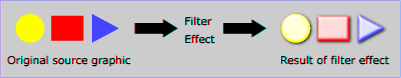