W3C Note, 03-Dec-1998
This document has been submitted to the World Wide Web Consortium (see Submission Request, W3C staff comment). The submission includes a DTD and two Java class definitions: DrawMLShape and DrawMLPainter.
This document is a NOTE made available by W3C for discussion only. This indicates no endorsement of its content, nor that W3C has, is, or will be allocating any resources to the issues addressed by the NOTE.
This document is the DrawML specification. DrawML is an application of Extensible Markup Language (XML) 1.0.
DrawML is a 2D scalable graphics language designed to facilitate the creation of simple technical drawings. Furthermore (and most importantly), DrawML focuses on the process of maintaining and refining a drawing. A drawing should be as easy to update as the document it resides in.
DrawML is based on the following requirements and criteria:
It should be possible to embed drawings in SGML/XML documents in the same way as CALS tables are embedded.
It should be possible reuse elements from the parent DTD inside the embedded drawing.
When structure is added to drawings, it should be possible to define algorithms to handle the positioning and automatic resizing of visual elements.
The typical drawing is not WYSIWYG.
The reason for the focus on maintenance is the increased importance of intranets. Up to now internet technology has been used primarily for publishing. People working within an intranet expect to create and change documents on-the-fly.
DrawML is a very simple language. It only defines five elements.
A drawing is introduced in a document with the drawml element.
The shape element is a generic element obtaining its properties from a Java class.
The line element draws a line between two or more positions.
The pos element defines a position in a line.
The lmward (drawml spelled backwards!) element is the element that switches context back to parent DTD elements.
A DrawML drawing is embedded in the SGML/XML document. If required parent DTD elements can be embedded in the DrawML drawing. Compare to a CALS table, where the content model for a cell is declared in the main DTD. In DrawML it is possible to insert paragraphs, lists, images, tables, etc. inside a drawing.
There are several advantages accruing from a tight integration of the document and the drawings it contains.
It is easy to cut and paste objects between a drawings and its surroundings.
Simpler, unified interface for handling text.
Text inside drawings is searchable, can be spell-checked, its case can be changed, etc.
A drawing can contain complex SGML/XML text structure (paragraphs, lists, tables).
There is no need for external entities.
References (id/idref, XLink) can be made to and from drawings.
The drawml element introduces a drawing in a document. At this point the "rendering engine" enters the DrawML mode in which the elements inside the drawing are drawn in accordance with the rules set forth in this specification. Somewhere in the drawing we want to include other non drawing elements. The lmward element (drawml spelled backwards!) temporarily leaves the DrawML mode and enters the ordinary rendering mode.
In the following example a paragraph with an emphasized word is written inside a rectangular shape.
<drawml>
 <shape type="rectangle">
  <lmward>
   <p>This is <em>my</em> text</p>
  </lmward>
 </shape>
</drawml>

We expect a table cell to adjust to its content and a paragraph to adjust to the frame width and we should expect similar functionality in a drawing.
One of the important concepts underlying DrawML is that shapes adjust to their content by default (just like cells in a table). A DrawML shape may contain other shapes.
For instance a shape will expand if the text placed inside it does not fit.
<drawml>
 <shape type="rectangle"></shape>
 <shape type="rectangle" width="100">
  <lmward>
   <p>This is <em>my</em> text</p>
  </lmward>
 </shape>
</drawml>

In the above case the width of the rectangle was explicitly set, which forced the text in the paragraph to wrap.
By placing shapes inside other shapes it is possible to arrange and group intelligently. The parent shape can be invisible and thus be used for the sole purpose of grouping. By default, shapes are arranged horizontally.
<drawml>
 <shape type="rectangle">
  <shape type="rectangle">
   <lmward>Hello</lmward>
  </shape>
  <shape type="rectangle">
   <lmward>World</lmward>
  </shape>
 </shape>
</drawml>

DrawML drawings work with structures rather than coordinate positions. When the user adds a new shape in the structure the application will make room for the new shape automatically.
<drawml>
 <shape type="rectangle">
  <shape type="rectangle">
   <lmward>Hello</lmward>
  </shape>
  <shape type="rectangle">
   <lmward>new</lmward>
  </shape>
  <shape type="rectangle">
   <lmward>World</lmward>
  </shape>
 </shape>
</drawml>

Shapes can also be arranged vertically.
<drawml>
 <shape type="rectangle" arrange="vertical">
  <shape type="rectangle">
   <lmward>Hello</lmward>
  </shape>
  <shape type="oval"></shape>
  <shape type="oval"></shape>
  <shape type="rectangle">
   <lmward>World</lmward>
  </shape>
 </shape>
</drawml>

A position can be explicitly defined using a coordinate. This coordinate is relative to its parent shape so when a parent is moved, its child is moved with it. Each shape defines a coordinate system for its children.
<drawml>
 <shape type="rectangle">
  <shape type="oval" x="100" y="20">
  </shape>
 </shape>
</drawml>

Drawing objects are often connected, e.g., an arrow points from one object to another, a group of objects are connected to a parent object in a hierarchical structure, etc. If objects are moved connections should adjust to the new layout. This effect is often referred to as the "rubber band" effect.
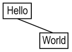
In DrawML shapes may have one or more hook positions. These positions are suitable connection points. Connections are defined with the line element. A connection consists of two or more positions (pos elements). Each position is either glued to a hook position in a shape or explicitly assigned a coordinate position.
A rectangle, for example, typically has four hook positions; W, N, E and S (west, north, east and south).
<drawml>
 <shape type="rectangle" shape-id="d1">
  <lmward>Hello</lmward>
 </shape>
 <shape type="rectangle" x="50" y="50" shape-id="d2">
  <lmward>World</lmward>
 </shape>
 <line>
  <pos attach-to="d1" attach-point="S"/>
  <pos attach-to="d2" attach-point="N"/>
 </line>
</drawml>
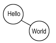
Sometimes we may want to connect to the nearest point on a shape. This point is defined with the reserved hook name $nearest.
<drawml>
 <shape type="oval" shape-id="d1">
  <lmward>Hello</lmward>
 </shape>
 <shape type="oval" x="50" y="50" shape-id="d2">
  <lmward>World</lmward>
 </shape>
 <line>
  <pos attach-to="d1" attach-point="$nearest"/>
  <pos attach-to="d2" attach-point="$nearest"/>
 </line>
</drawml>
A line may connect several shapes. The line is by default drawn from shape to shape in the order of the positions.
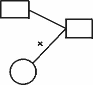
On the other hand, a line can connect the involved shapes in three other ways: horizontally, vertically or centrally. The "centre of gravity" gives the renderer a default "central position" to be used as visualized below.
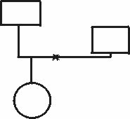
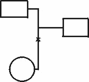
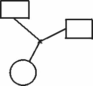
The "central position" can be specified explicitly.
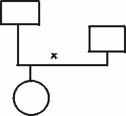
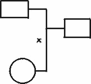
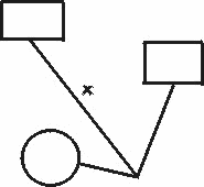
The success of a standard often depends on its extendability. In DrawML all shapes are defined using Java, including rectangles and circles. The power of a programming language such as Java gives shape developers the necessary flexibility.
The following example is a house shape.
<drawml>
 <shape type="house">
 </shape>
</drawml>

When child shapes are positioned inside the shape the house should be bigger. It is the shape that decides how the house should adapt to its children. Note that the roof is not getting any higher, ,just wider.
<drawml>
 <shape type="house">
    <lmward>A house</lmward>
 </shape>
</drawml>

The Java shapes have a CalcSize() method that calculates each size. The renderer calls these routines when calculating the individual positions. The interesting point is that each shape asks the renderer for the size of the shape's children.

public void CalcSize()
{
   SetW( 7 + 5 + GetWChild() + 5 + 7 );   // Set shape width
   SetH( 10 + 5 + GetHChild() + 5 );      // Set shape height
}
After calculating positions the renderer then calls the DrawShape() routine for each shape. The Java class uses a PAINTER class to do the actual drawing.
The Java-code to draw the house is as follows:
public void DrawShape()
{
   Painter.NewPath();                          // Clear painter
   Painter.MoveTo( 0, 10 );
   Painter.LineTo( MyW()/2, 0 );
   Painter.LineTo( MyW(), 10 );
   Painter.ClosePath();
   Painter.Stroke();                           // Draw roof
   Painter.NewPath();
   Painter.MoveTo( 7, 10 );
   Painter.LineTo( MyW() - 7, 10 );
   Painter.LineTo( MyW() - 7, MyH() );
   Painter.LineTo( 7, MyH() );
   Painter.ClosePath();
   Painter.Stroke();                           // Draw front
}
The following example demonstrates several DrawML features.
<drawml>
 <shape arrange="vertical" visibility="invisible" shape-id="i1">
  <shape shape-id="d1">
   <lmward>
    <title>System X</title>
   </lmward>
  </shape>
  <shape visibility="invisible" shape-id="i2">
   <shape shape-id="d1">
    <lmward>
     <subtitle>Subsystem A</subtitle>
     <para>This is text in a para.</para>
    </lmward>
   </shape>
   <shape shape-id="d2">
    <lmward>
     <subtitle>Subsystem B</subtitle>
     <list>
      <list-item>This is a list.</list-item>
      <list-item>This is the second item.</list-item>
     </list>
    </lmward>
   </shape>
  </shape>
  <line connect="horizontal">
   <pos attach-to="d1"/>
   <pos attach-to="i2.d1" arrowed="yes"/>
   <pos attach-to="i2.d2" arrowed="yes"/>
  </line>
 </shape>
</drawml>
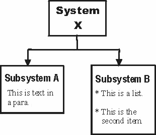
The drawing consists of two invisible objects that have the sole purpose of grouping other objects, horizontally and vertically. Elements from the parent DTD (title, subtitle, para, list and list-item) are used inside the rectangles. Connections are glued to objects.
The drawing is easy to maintain and refine. If a new box is added or if more text is added in any rectangle, an application will still be capable of formatting the drawing appropriately.
drawmlA drawml element defines a drawing area. It has a default size and is invisible.
(shape|line|lmward)*
| Name | Value(s) | Default Value |
| width | points | (automatic) |
| height | points | (automatic) |
| min-width | points | 50 |
| min-width | points | 50 |
WIDTH, HEIGHTThe WIDTH and HEIGHT attributes specify an explicit drawing size. By default a drawing adjusts to its content.
MIN-WIDTH, MIN-HEIGHTThe MIN-WIDTH and MIN-HEIGHT attributes define the extent to which a drawing is allowed to shrink.
shapeThe shape element is a generic element. The characteristics of the shape is defined in a separate Java class. The shape can be anything from a simple rectangle to a complicated figure.
(shape|line|lmward)*
| Category | Name | Value(s) | Default Value |
| Main | type | shape name | "rectangle" |
| shape-id | shape id | ||
| visibility | "visible", "invisible", "dimmed" | "visible" | |
| Position | x | points | (automatic) |
| y | points | (automatic) | |
| z | points | 0 | |
| delta-x | points | 0 | |
| delta-y | points | 0 | |
| Size | width | points | (automatic) |
| height | points | (automatic) | |
| min-width | points | 50 | |
| min-height | points | 50 | |
| max-width | points | (none) | |
| max-height | points | (none) | |
| perfect | "yes", "no" | "no" | |
| Line | line-width | points | 1 |
| line-color | color | "black" | |
| Fill | filled | "yes", "no" | "yes" |
| fill-color | color | "white" | |
| Shadow | shadowed | "yes", "no" | "no" |
| shadow-color | color | "gray" | |
| shadow-x | points | 5 | |
| shadow-y | points | 5 | |
| Children | arrange | "horizontal", "vertical" | "horizontal" |
| child-separation | points | 5 | |
| child-halign | "left", "center", "right" | "center" | |
| child-valign | "top", "center", "bottom" | "center" | |
| child-wpad | points | 5 | |
| child-hpad | points | 5 |
typeThe type attribute defines the shape type.
<shape type="house">
  ...
</shape>
The DrawML engine searches for a Java class with the specified type name (in this case house.class).
shape-idThe shape-id attribute assigns an id to the shape. It must be unique among all its sibling.
visibilityThe visibility attribute specifies whether a shape is visible, invisible or dimmed.
x, yThe x and y attributes specify the shape position relative its parent. If these attributes are not specified the shape is positioned according to automatic positioning rules.
<shape type="rectangle">
 <shape type="rectangle" x="20" y="40">
 </shape>
</shape>
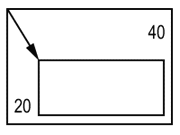
zThe z attribute defines the order in which shapes are drawn inside a shape. Shapes with lesser Z values are overlaid by shapes with greater Z values. If z is not specified or shapes have the same Z value, the shapes are drawn in the order they are specified.
delta-x, delta-yThe delta-x and delta-y attributes define a delta displacement from the current position. The current position is the position specified explicitly with the attributes x and y or implicitly with the automatic positioning algorithm.
<shape type="rectangle">
 <shape type="rectangle" delta-y="40">
 </shape>
</shape>
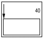
width, heightThe width and height attributes specify the explicit size of a shape. Automatic resizing will be inhibited.
min-width, min-height, max-width, max-heightThe min-width and min-height attributes define the extent to which a shape is allowed to shrink.
The attributes max-width and max-height define the extent to which a shape is allowed to grow.
perfectThe perfect attribute has different meanings for different shapes. The shape designer decides what "perfect" means for his shape. A perfect rectangle will be a square and a perfect oval will be a circle.


line-widthThe line-width attribute defines the width of a shape's outline in points. Default line width is 1 point.
line-colorThe line-color attribute determines the outline color of a shape. The default value is black.
filledThe filled attribute defines whether the shape is filled or not.
fill-colorThe fill-color attribute determines the fill color of a shape. The default value is white.
shadowedThe shadowed attribute defines whether a shape is shadowed or not.
shadow-colorThe shadow-color attribute determines the shadow color of a shape.
shadow-x,shadow-yThe shadow-x and shadow-y attributes specifies the offset of the shadow. Negative values are possible. Default offset is 10 points.
arrangeThe arrange attribute specifies whether children are positioned horizontally (default) or vertically.
child-separationThe child-separation attribute defines the spacing of positioned child shapes. The default is 5 points.

child-valign, child-halignThe child-valign and child-halign attributes define how child shapes are aligned vertically and horizontally.
<shape type="rectangle" child-valign="top">
 <shape type="rectangle" height="10"></shape>
 <shape type="rectangle" height="30"></shape>
 <shape type="oval"></shape>
</shape>

<shape type="rectangle" child-valign="bottom">
 <shape type="rectangle" height="10"></shape>
 <shape type="rectangle" height="30"></shape>
 <shape type="oval"></shape>
</shape>

child-wpad, child-hpadThe child_wpad and child-hpad attributes define a padding area around the children.
lineA line is a shape built up from positions. It must have at least two positions.
(pos, pos+)
<line>
 <pos x="0" y="0"/>
 <pos x="50" y="50"/>
 <pos x="100" y="50"/>
 <pos x="50" y="0"/>
</line>

| Name | Value(s) | Default Value |
| z | integer | |
| connect | "serial", "vertical", "horizontal", "central" | "serial" |
| grav-x | points | (centre of gravity) |
| grav-y | points | (centre of gravity) |
| line-width | points | 1 |
| line-color | color | "black" |
zThe z attribute defines the order in which shapes are drawn inside a shape. Shapes with lesser Z values are overlaid by shapes with greater Z values. If z is not specified or shapes have the same Z value, the shapes are drawn in the order they are specified.
connectThe connect attribute specifies how the included positions should be connected.
grav-x, grav-yThe grav-x and grav-y attributes defines an explicit "centre of gravity" point used when connect type is horizontal, vertical or central.
line-widthThe line-width attribute defines the width of the line in points. Default line width is 1 point.
line-colorThe line-color attribute determines the color of the line. The default value is black.
posA pos element is primarily used to define lines. A position can be an explicit coordinate position or hook point on a shape. defined
EMPTY
<pos attach-to="d1" attach-point="S" />
<pos attach-to="d1" attach-point="S" delta-x="10" delta-y="-5" />
<pos x="15" y="40" />
| Name | Value(s) | Default Value |
| x | points | |
| y | points | |
| attach-to | shape id | |
| attach-point | hook name | |
| delta-x | points | 0 |
| delta-x | points | 0 |
| arrowed | points | "no" |
x, yThe x and y attributes define an explicit coordinate for the position.
attach-to, attach-pointThe attach-to attribute specifies a shape ID and the attach-point attribute specifies a hook position on that shape.
<pos attach-to="d1" attach-point="S" />
To address a shape inside another shape the id is qualified with the parent shape id. This could be done to any level.
<pos attach-to="town.house1.door" attach-point="S" />
delta-x, delta-yThe delta-x and delta-y attributes define a delta displacement from the current position. The current position is the position specified with the attributes x and y or with the attach attributes.
arrowedThe arrowed attribute specifies if an arrow should be drawn at the position.
lmwarDThe lmward element is an element that switches context back to parent DTD elements. It serves as a "container" element for paragraphs, images, tables, lists or whatever element that is allowed inside the drawing.
ANY
(The content model could be redefined in the main DTD by means of the lmward-content parameter entity)
<lmward>
 <para>This is a paragraph.</para>
 <warning>And this is a warning!</warning>
</lmward>
The unit for coordinates and dimensions is the point. Examples of valid values:
0
-4
64.75
99999
A color is specified as in the CSS standard, either with a predefined name, e.g. "red" or with an RGB value, e.g. rgb(255,0,0).
The DrawML element and attribute definitions are in a separate file and should be included in the DTD in the following manner.
<!ENTITY % drawml SYSTEM "drawml.elm" >
%drawml;
DrawML shapes are implemented with Java. When the renderer reads a DrawML drawing it discovers shapes of various types. Each shape type should correspond to a Java class file. The renderer then asks each Java shape to report its size, its hooks and where its first child, if any, should be positioned. When all this information is collected the renderer is able to calculate the coordinate position for each shape. It then calls each shape to draw itself.
A Java shape should extend the DrawMLShape base class. The actual drawing of a shape is accomplished through the DrawMLPainter class.