Henrik
Frystyk, July 1994
 Introduction to the Internet
 This chapter gives an overview of the
Internet. It presents the history and the basic model of the
Internet, but it is not an attempt to describe the Internet in all its
detail which would be out of scope at this place. Please see Douglas Comer for an excellent
description of the Internet. The structure of the document is as
follows:
- Architectural Model
- Address Scheme
- Domain Name Server
- Gateways and Routing
In the late 1960s the American Defense Advanced Projects Research
Agency, ARPA (later DARPA) started a research project on the subject
of computer networks. One of the first results of this project was an
experimental four node network starting in 1969. Later the network
expanded to include several military installations and scientific
research centers. In the mid 1970s work began towards the Internet
with the architecture and protocols taking their current form around
1978-79.
The Internet as we know it today started around 1980 when DARPA
started to use the TCP/IP protocol stack on all installations
connected to the DARPA Internet. The transition ended in the beginning
of 1983 when TCP/IP became the only protocol stack allowed on the
Internet. This is still the current situation on the Internet, but now
it has grown to several thousands of nodes and millions of users. The
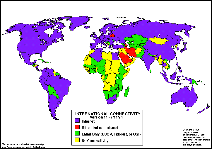
countries connected to the Internet are illustrated in the figure below.
In 1988, DARPA decided that the experiment of ARPANET was complete and
started to dismantle the ARPANET that, until then, was the backbone of
the Internet. However at the same time, the American National Science
Foundation established the NFSNET which then became the new backbone
network with a capacity (1992) of 45 MBPS.
Many
Internet organizations other than DARPA have an important influence
on the further development of the Internet. A few of them are
mentioned below:
- The Internet Activities Board (IAB)
- This organization was created in 1983 in order to guide the
evolution of the Internet development. It now has two major
components: Internet Engeneering Task Force and the Internet Research
Task Force.
-
Internet Engeneering Task Force (IETF)
- The IETF is the protocol engeneering, development, and
standardization branch of the Internet Architecture Board (IAB). IETF
manages the Request for Comments
(RFC) documents
- Internet Research Task Force (IRTF)
- The IRTF is the research and development branch of IAB. They do research in new network technologies and
- InterNIC Information Services
- The InterNIC is a collaboration project of three organizations:
General Atomics, AT&T, and Network Solutions, Inc. Their goal is
to make networking and network information more easily accessible to
researchers, educators and the general public. They work together with
the Network Information Centers (NICs) located throughout the
Internet.
Architectural Model
The term "Internet" is a generalization that covers thousands of
interconnected networks around the world based on very different
technologies. The networks differ in almost any possible network
specific parameter such as transmission medium, geographical size,
number of nodes, transmission speed, throughput, reliability etc. The
only reason why this generalization is possible is because the
Internet is based on an abstraction that is independent of the
physical hardware. In short, it represents a homogeneous interface to
its users in spite of the heterogeneous hardware that it is based on.
The diversity among networks connected to the Internet is partly due
to an evolution of technology resulting in new networks having higher
reliability, better throughput etc. However, there will (at least for
a long time) exist a need for fundamental different network
architectures as no network technology today can supply a solution
that covers all aspects of internetworking.
This section introduces the basic architecture of how the Internet is
organized. The description starts at a certain abstraction level that
does not include a description of the underlying physical network
technologies such as Ethernet, Token Ring, FDDI etc. These are all
described in Computer Networks.
The basic idea of an internet is to provide the possibility of
transporting data from one network to another through a connection in
a way that both parties agree on and understand. The connection
between the two consists of a gateway computer that is physically or
logically connected to both networks (logically in the case of a
cordless network). The situation between two networks looks like:

Each cloud is a network with an arbitrary number of connected
nodes. The gateway between them serve as the only way of exchanging
data directly between the two networks. Later in this chapter it is
described how two hosts can communicate even though they are not
connected directly but must go through intermediate networks.
Address Scheme
In order to reference any node as a unique point on the Internet, a
global two dimensional 32-bit integer address space has been defined
which gives a maximum number of 4G connected nodes on the Internet.
The first element is a netid and the second is a nodeid, that is:
address = (netid, hostid)
A common notation for specifying an Internet address is by using four
fields of decimal integer numbers ranging from 0 to 255 separated by
decimal points, e.g.:
128.141.201.214
which is the IP-address of the World-Wide Web info server at CERN.
Address Classes
In order to provide IP-addresses which suit both large networks with
millions of hosts and small networks with a few hundred hosts, the
netid part and the hostid part can occupy a varying part of the
IP-address. The number of possible nodes on a network, being the
amount of bits assigned to the hostid, categorizes the address space
into 5 classes:
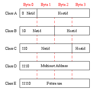
The definition of the classes is as follows:
- Class A
- This class has a 1 byte netid and a 3 byte hostid. As networks in
this category are characterized by having a 0 as the first bit in the
address, the maximum number of networks is 128. However, as 24 bits
are available for the hostid, each network can contain 16M
connections. A network can be categorized by the first fields in the
address and for a Class A network the value of first field is in the
range 0-127.
- Class B
- Class B networks have 2 bytes for the netid, but as they are
required to start with the bit combination 10b, the maximum number of
networks is 16K. The number of connected nodes is 64K and the value of
the first field ranges from 128-191 and the second from 1-254.
- Class C
- This class is for small networks with a maximum number of nodes
limited to 256. This class is characterized by having the leading bit
pattern 110b which leaves the maximum number of networks to 2M. The
value of the first field is from 192-233, the second from 0-255, and
the third from 1-254.
- Class D
- Class D networks are networks without the possibility of
addressing any individual node. All 32 bites are used by the netid and
hence any reference to the network is automatically a broadcast
message to all the connected hosts. The characteristic leading bit
pattern for this class is 1110b.
- Class E
- This is currently not in use but reserved for future use.
However, the characteristic leading bit pattern for this class is
defined as 11110b.
From this description it can be seen that the IP-address given above
is a Class B network with the possibility of 64K nodes.
An interesting thing to note about having the IP-address containing
information of the network is that a gateway as a consequence of being
connected to two networks must also have two IP-addresses in order to
be accessible from both sides. This is the reason for not referring to
a number of hosts but nodes or connections to the network. In the Gateways and Routing it is described how the current
addressing scheme influences the routing algorithms used on the
Internet.
Physical Addresses
It is important to note that Internet addresses are an abstraction
from the addresses in a physical network implementation like Ethernet.
They assure that the same addressing scheme can be used in every part
of the Internet regardless of the implementation of the underlying
physical network. In order to do this, a binding must exist between
the IP-address and the physical address. Dependent on the physical
network addressing scheme, this binding can either be static or
dynamic. An example of the latter is the Ethernet addressing scheme
that is a 48-bit integer. As it is not possible to map 48 bit into a
32-bit IP-address without loosing information, the binding must be
determined dynamically. The Addressing Resolution Protocol
(ARP) is specially designed for binding Ethernet addresses
dynamically to IP-addresses but can be used for other schemes as well.
Subnetworks
As will be explained in the section Gateways and
Routing, Internet routing between gateways is based on the netid
part of the IP-address. In the past few years a very large number of
small networks with only a few hundred nodes have been connected to the
Internet. Having so many netids makes the routing procedure
complicated and time consuming. One solution to this is to introduce a
subnet addressing scheme where a single IP-address spans a set of
physical networks. This scheme can also be used to divide a large
number of nodes into logical groups within the same network.
The scheme is standardized and described in the RFC IP Subnet Extension.
The idea is basically to use three coordinates in the IP-address
instead of two, that is:
address = (netid, subnetid, nodeid)
However, the subnetid only has a special meaning "behind" the front
subnet gateway. The rest of the Internet can not see it and treats the
subnetid and the nodeid as the hostid. Only the
gateways indicated in the figure need to know of the subnets and can
then make the routing accordingly.
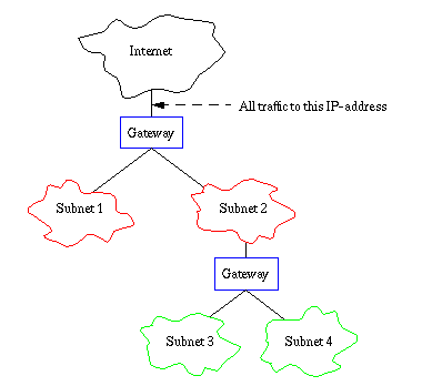
Furthermore, the subnet hierarchy does not have to be symmetric. This
is indicated in the figure where subnet 3 and 4 are subnets of subnet
2, whereas subnet 1 does not have any subnets.
A 32-bit subnet mask for each level in the subnet hierarchy is
required in order to make the gateway routing possible between the
subnets. This mask specifies what part of the IP-address is the
subnetid and what part is the nodeid by simple boolean AND'ing.
Special Addresses
One advantage of having the network encoded as a part of the
IP-address is that it is possible to refer to the network as well as
individual hosts. Three special cases have been specifically allocated
for exploiting this feature:
Broadcast Messages
It is possible to generate as broadcast message to all nodes on a
network by specifying the netid and letting the hostid be all 1s.
However, there is is no guarantee that the physical actually supports
broadcast messages, so the feature is only an indicator. It is not
possible to make a broadcast message to the whole Internet in one
operation. This is to prevent the network from flooding the Internet
with global broadcast messages.
This network
Situations might appear where a host on a network does not know
the netid of the network that it is connected to. This happens every
time a host without stationary memory wants to get on to the net.
However, the host does know its physical address which is
sufficient for communicating locally within the network. In this
situation it sets the netid to 0 and sends out a broadcast message on
the local network. Two Internet protocols are available for doing
this:
- Reverse Address
Resolution Protocol (RARP)
- This protocol is adapted from the Address Resolution
Protocol that is especially created to resolve 48-bit physical
Ethernet addresses into 32-bit IP-addresses. Only a dedicated RARP
server on the network will answer the reply by filling out the netid
and send it back to the requester. In case the main RARP server is
down a backup RARP can be chosen to perform the job.
- Internet Control
Message Protocol (ICMP)
- This is a generic low level error and information protocol that
can be used for sending error and information messages between any
host gateway (also from gateway to gateway and host to host). It also
has the possibility of sending out a simple information
request message, and this can be used to obtain the netid of the
network. In this situation, the gateways on the local network will
respond to the request with an information message having the right
netid.
Local Host
By convention the Class A address 127.0.0.1 is
known as a loopback address for the local host. This address
provides the possibility of accessing resources local to your own
system. On Unix platforms, this is defined in the /etc/hosts
system file.
Domain Name Server
This section is an introduction to the Internet Domain Name Service
(DNS). See DNS and Bind for a
complete description of the service. The DNS is build on top of a
distributed database where every data record is indexed by a name that
is a part of the Domain Name Space. The index itself is a
hierarchically organized tree structure as illustrated in the
following figure:
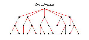
where the top node is called the root domain with the null
label (empty string) but referenced as a single dot. Each node in the
tree is labeled with a name consisting of at most 63 characters taken
from the set of
- letters from A-Z (case insensitive)
- digits from 0-9
- hyphen
The advantage of having a hierarchical structure of the name space is
that administration of the space can be delegated to different
organizations without any risk for name collision. This is very
important as the size of the DNS database is foreseen to be
proportional to the number of users on the Internet as the database not
only can contain information about hosts but also about personal
mail addresses.
The structure shown above is very similar to the Unix file system. The
most important difference is that a record in the DNS database is
indexed from the bottom of the tree and up whereas a Unix file is
indexed from the top of the tree, e.g.:
- info.cern.ch
- The info is the host name and the cern.ch is
the domain name.
- /usr/local/bin/emacs
- emacs is the file name and /usr/local/bin is
the path
Another similarity is aliases that are pointers to the
official host name in the DNS database. In the Unix file system it is
implemented as (soft) links.
DNS is a client-server based application consisting of the Domain Name
Servers and the resolvers. A server contains information about some
segment of the DNS database and makes it available to clients or
resolvers. Resolvers are often just software libraries that is linked
into any Internet program by default.
In the next section it is described what happens when a host has more
than one physical connection to the Internet and hence more than one
host name.
Gateways and Routing
When a message is to be send from one host to another, some mechanism
must provide the functionality of choosing the exact path of which the
message is to be transmitted. When routing a message, two distinct
situations can occur:
- Direct Routing
- The transmitting and receiving host are connected to the same
physical network
- Indirect Routing
- The transmitting and receiving host are separated by one or many
networks
In the first case, routing is a question of resolving the IP-address
into a physical address as described in Physical
Addresses. Then the sender encapsulates the IP-datagram into
physical frames and sends it directly to the destination. This section
will give an overview of how the latter case is handled using
gateways.
Routing does not lead to changes in the original message. The source and
destination address remain the same. The source always specifies the address
of the original host and the destination address is that of the destination
host. The original message is instead encapsulated in another message in order
to specify the next hop address.
The standard routing algorithm used on the Internet is based on routing
tables situated in every gateway. An advantage of the Internet Address Scheme is that it is sufficient for a
gateway to look at the netid part of the IP-address in order to find the
destination network. Only the gateway directly attached to the destination
network needs to look at the hostid in order to resolve the IP-address into a
physical address.
However, even if the routing tables only contains netids, it would be
impossible to have routing information on every node on the Internet.
The solution to this problem is to use partial routing information.
The idea is to first look at the routing table to see if the netid is
there. If it is not then the gateway sends the IP-datagram to a
default destination as illustrated in the following figure.
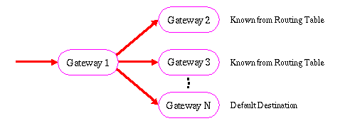
As the default gateway again might send it to its default destination
a mechanism must assure that the routing converge towards the final
destination. This guarantee is provided by a set of core gateways that
contain full routing tables. All partial routing finally ends up in an
core gateway and the message can then be directed to the right subnet
of the Internet.
Until no assumptions have been made on how the gateways actually get
the routing tables and how updated information gets spread throughout
the Internet. There are several protocols to do this but before
mentioning them, it is necessary to look into the organization of
gateways on the internet.

The CORE Gateways are a small group of gateways such as the NFSNET backbone net which
guarantees that the partial routing algorithm will converge towards a final
destination. An autonomous systems is a set of networks organized under the
same administrative authority. All routing information within the system are
passed to other autonomous system via a few exterior gateways close to the
outer edge of the system. The protocols indicated in the figure are shortly
summarized below:
- GGP Gateway-to-Gateway Protocol
- This is set of protocols used internally between core gateways in order
to exchange updated routing tables. They are often based on the Shortest Path
First (SPF) algorithm where a data base contains the complete network topology
and connectivity in every gateway. Then the core gateway can compute the best
shortest routing path and guarantee that it will converge.
- EXP Exterior Gateway Protocol
- The Exterior Gateway Protocol is
used to exchange routing tables between a few dedicated gateways across
autonomous systems.
- IGP Interior Gateway Protocol
- Actually this is a set of different protocols that all have the same
purpose of having consistent routing tables internally in an autonomous
system. The best known is Routing
Information Protocol (RIP). This protocol is based on a vector distance
algorithm defined as the minimum number of hops between gateways.
International Standards Organization (ISO) has defined the Intermediate System-to-Intermediate
System (IS-IS) as another IGP protocol. This means that OSI Networks and TCP/IP networks can share
routing information.
Problems in the Internet Model
Now when the basic properties of the Internet model has been
introduced some problems or weaknesses in the current model have
become clear. This section will shortly summarize the most important
limitations in the current Internet architecture.
Address Scheme
The basic disadvantage of having the netid as a part of the IP-address
is that if a host is moved from one place to another it must have a
new IP-address. As more and more portable computers are connected to
the Internet this has turned out to be a real problem in the address
scheme.
Routing
When routing is based on the netid of the IP-address multi-homed hosts
might have a significant difference in access time dependent of the
IP-address used.

If Host B in the figure wants to communicate with Host C
in the figure and chooses the IP-address of node e then the
message have to go through Host A. Unless the system
administrators explicitly have told the local part of the Domain Name
Service to return the IP-address of node d there is no way for
Host B to know the optimal route.
Security
Another important aspect not described here is security
considerations when using the Internet. What means do people have
to gain access to classified information when communicating to
Internet sites. Today security precautions on the Internet is often
based on the assumption that the transport service provided by the
Internet can be considered as a trusted carrier. This is equivalent to
the generally accepted assumption that letters send via the public
postal system is actually delivered to the addressee without being
read by anyone during transportation.
This is, however, not true on the Internet and many problems have
arisen simply from people listening to the net traffic. Especially
protocols like FTP and
the Telnet protocol
(the control connection in the FTP protocol is actually a telnet
connection) have proven to be very insecure as passwords are
transmitted unencoded across the Internet.
 Henrik
Frystyk, frystyk@info.cern.ch, July 1994
 This chapter gives an overview of the
Internet. It presents the history and the basic model of the
Internet, but it is not an attempt to describe the Internet in all its
detail which would be out of scope at this place. Please see Douglas Comer for an excellent
description of the Internet. The structure of the document is as
follows:
In the late 1960s the American Defense Advanced Projects Research
Agency, ARPA (later DARPA) started a research project on the subject
of computer networks. One of the first results of this project was an
experimental four node network starting in 1969. Later the network
expanded to include several military installations and scientific
research centers. In the mid 1970s work began towards the Internet
with the architecture and protocols taking their current form around
1978-79.


 Henrik
Frystyk, frystyk@info.cern.ch, July 1994