Model-Based Approaches for User Interfaces
Introduction
The purpose of Model-Based Design is to identify high-level models, which allow designers to specify and analyse interactive software applications from a more semantic oriented level rather than starting immediately to address the implementation level. This allows them to concentrate on more important aspects without being immediately confused by many implementation details and then to have tools which update the implementation in order to be consistent with high-level choices. Thus, by using models which capture semantically meaningful aspects, designers can more easily manage the increasing complexity of interactive applications and analyse them both during their development and when they have to be modified [[P05]].
In recent years model-based approaches have evolved in parallel with the aim of coping with the different challenges raised by the design and development of UIs in continuously evolving technological settings. We can identify various generation of works in this area [[PSS09]]. The first generation of model-based approaches in which the focus was basically on deriving abstractions for graphical UIs (see for example UIDE [[FS94]]). At that time, UI designers focused mainly on identifying relevant aspects for this kind of interaction modality.
Then, the approaches evolved into a second generation focusing on expressing the high-level semantics of the interaction: this was mainly supported through the use of task models and associated tools, aimed at expressing the activities that the users intend to accomplish while interacting with the application (see for example Adept [[J93]], GTA [[vdV94]], ConcurTaskTrees (CTT) [[P99]]).
Afterwards, thanks to the growing affordability of new interactive platforms, in particular mobile ones, the work of UI designers mainly focused on how to cope with the relentless appearance of new devices on the market and the need to cope with their different characteristics. As previously pointed out by Myers et al. (2000), the increasing availability of new interaction platforms raised a new interest in model-based approaches in order to allow developers to define the input and output needs of their applications, vendors to describe the input and output capabilities of their devices, and users to specify their preferences. However, such approaches should still allow designers to have good control on the final result in order to be effective.
After having identified relevant abstractions for models, the next issue is specifying them through a suitable language that enable integration within development environments, so as to facilitate the work of the designers and developers. For this purpose, the notion of User Interface Description Language (UIDL) has emerged in order to express any model.
It is expected that a model-driven approach of UI development could represent an engineering effort attempting to systematize UI development. It does so by constructing high-level requirements and, progressively, transforms them to obtain specifications that are detailed and precise enough to be rendered or transformed into code. This type of approach is referred to in the Software Engineering literature as the transformational approach.
Any method and development tool is expected to effectively and efficiently support a flexible development lifecycle, enforcing a minimum number of priority constraints. These constraints should define which development artifacts must be specified before others, suggesting for example how and when to proceed from one development step to another.
The CAMELEON Reference Framework
The CAMELEON Unified Reference Framework [[CCB02]] [[CCTLBV03]] was produced by the EU-funded CAMELEON Project [[CAM-Proj]] and results from two key principles:
- A Model-Based approach
- Coverage of both the design and run-time phases of a multi-target UI
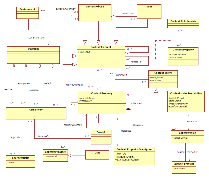
The Context of Use
Context is an all-embracing term. Composed of “con” (with) and “text”, context refers to the meaning that must be inferred from the adjacent text. As a result, to be operational, context can only be defined in relation to a purpose, or finality [[CRO02]]. In the field of context-aware computing a definition of Context that has been largely used is provided by [[Dey2000]]: Context is any information that can be used to characterize the situation of entities (i.e. whether a person, place or object) that are considered relevant to the interaction between a user and an application, including the user and the application themselves. Context is typically the location, identity and state of people, groups and computational and physical objects.
While the above definition is rather general, thus encompassing many aspects, it is not directly operational. Hence, we hereby define the Context of Use of an interactive system as a dynamic, structured information space that includes the following entities:
- a model of the User, U, (who is intended to use or is actually using the system)
- the hardware-software Platform, P, (which includes the set of computing, sensing, communication, and interaction resources that bind together the physical environment with the digital world)
- the social and physical Environment, E, (where the interaction is actually taking place).
The User represents the human being (or a human stereotype) who is interacting with the system. The characteristics modelled or relevant can be very dependant on the application domain. Specific examples are age, level of experience, the permissions, preferences, tastes, disabilities, short term interests, long term interests, etc. In particular, perceptual, cognitive and action disabilities may be expressed in order to choose the best modalities for the rendering and manipulation of the interactive system.
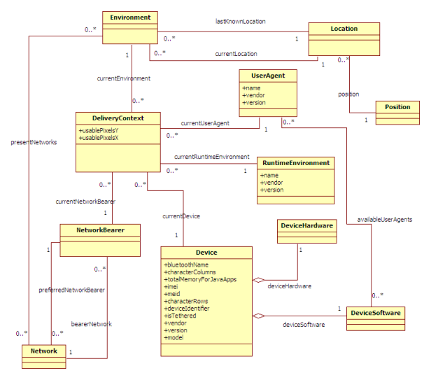
The Platform is modeled in terms of resources, which in turn, determine the way information is computed, transmitted, rendered, and manipulated by users. Examples of resources include memory size, network bandwidth, and input and output interaction devices. [[CCB02]] distinguishes between elementary platforms (e.g. laptop, PDA, mobile phone), which are built from core resources (e.g. memory, display, processor) and extension resources (e.g. external displays, sensors, mice), and clusters, which are built from elementary platforms. Resources motivate the choice for a set of input and output modalities and, for each modality, the amount of information made available. W3C's Delivery Context Ontology [[DCONTOLOGY]] is intended to define a standard Platform Model.
The Environment denotes the set of objects, persons and events that are peripheral to the current activity but that may have an impact on the system and/or users behavior, either now or in the future
(Coutaz and Rey, 2002). According to our definition, an environment may encompass the entire world. In practice, the boundary is set up by domain analysts whose role is to elicit the entities that are relevant to the case at hand. Specific examples are: user's location, ambient sound, lighting or weather conditions, present networks, nearby objects, user's social networks, level of stress ...
The relationship between a UI and its contexts of use leads to the following definitions:
- Multi-target (or multi-context) UI
- A multi-target (or multi-context) UI supports multiple types of users, platforms and environments. Multi-user, multi-platform and multi-environment UIs are specific classes of multi-target UIs which are, respectively, sensitive to user, platform and environment variations. [[CCTLBV03]]
- Adaptive UI
- An Adaptive UI refers to a UI capable of being aware of the context of use and to (automatically) react to changes of this context in a continuous way (for instance, by changing the UI presentation, contents, navigation or even behaviour).
- Adaptable UI
- An Adaptable UI can be tailored according to a set of predefined options. Adaptability normally requires an explicit human intervention. We can find examples of UI adaptability on those word processors where the set of buttons contained by toolbars can be customized by end users.
- Plastic UI
- A Plastic UI is a multi-target UI that preserves usability across multiple targets. Usability is not intrinsic to a system. Usability can only be validated against a set of properties set up in the early phases of the development process. [[CCTLBV03]]
Abstraction Levels
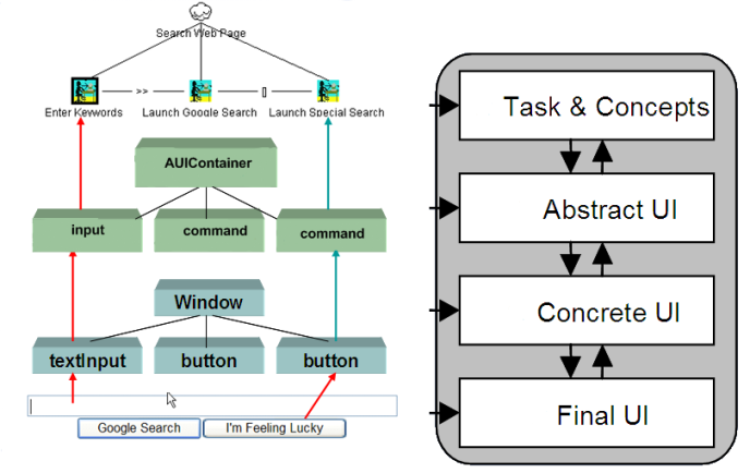
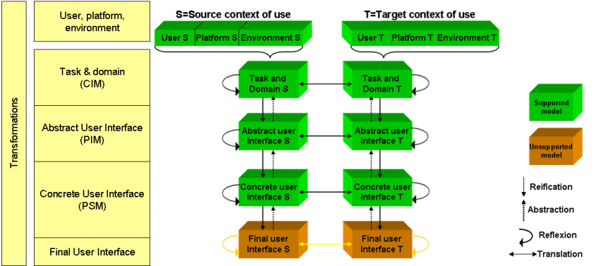
The CAMELEON Reference Framework, structures the development life cycle into four levels of abstraction, from the task specification to the running interface (see [[fig-cameleon]]):
- The Task and Concepts level (corresponding to the Computational-Independent Model–CIM–in MDE) which considers: (a) the logical activities (tasks) that need to be performed in order to reach the users’ goals and (b) the domain objects manipulated by these tasks. Often tasks are represented hierarchically along with indications of the temporal relations among them and their associated attributes.
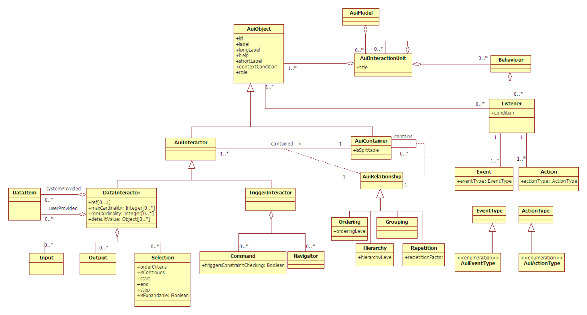
- The Abstract User Interface (AUI) (corresponding to the Platform-Independent Model–PIM– in MDE) is an expression of the UI in terms of interaction spaces (or presentation units), independently of which interactors are available and even independently of the modality of interaction (graphical, vocal, haptic …). An interaction space is a grouping unit that supports the execution of a set of logically connected tasks.
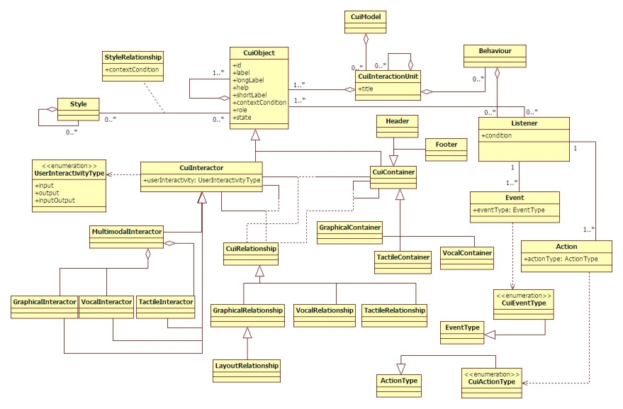
- The Concrete User Interface (CUI) (corresponding to the Platform-Specific Model–PSM– in MDE) is an expression of the UI in terms of “concrete interactors”, that depend on the type of platform and media available and has a number of attributes that define more concretely how it should be perceived by the user. "Concrete interactors" are, in fact, an abstraction of actual UI components generally included in toolkits.
- The Final User Interface (FUI) (corresponding to the code level in MDE) consists of source code, in any programming language or mark-up language (e.g. Java or HTML5). It can then be interpreted or compiled. A given piece of code will not always be rendered on the same manner depending on the software environment (virtual machine, browser …). For this reason, we consider two sublevels of the FUI: the source code and the running interface
These levels are structured with a relationship of reification going from an abstract level to a concrete one and a relationship of abstraction going from a concrete level to an abstract one. There can be also a relationship of translation between models at the same level of abstraction, but conceived for different contexts of use. These relationships are depicted on [[fig-cameleon]].
User Interface Description Languages
After having identified relevant abstractions for models, the next issue is specifying them through a suitable language that enable integration within development environments, so as to facilitate the work of the designers and developers. For this purpose, the notion of User Interface Description Language (UIDL) has emerged in order to express any aforementioned model.
A UIDL [[GGC09]] is a formal meta-language used in Human-Computer Interaction (HCI) in order to describe a particular UI independently of any implementation technology. As such, the UI might involve different interaction modalities (e.g., graphical, vocal, tactile, haptic, multimodal), interaction techniques (e.g., drag and drop) or interaction styles (e.g., direct manipulation, form fillings, virtual reality). A common fundamental assumption of most UIDLs is that UIs are modelled as algebraic or model-theoretic structures that include a collection of sets of interaction objects together with behaviours over those sets. A UIDL can be used during:
- Requirements analysis: in order to gather and elicit requirements pertaining to a UI of interest.
- Systems analysis: in order to express specifications that address the aforementioned requirements pertaining to a UI of interest.
- System design: in order to refine specifications depending on the context of use
- Run-time: in order to execute a UI via a rendering engine
The design process for a UIDL encompasses the definition of the following artefacts:
- Semantics. They express the context, meaning and intention of each UIDL abstraction captured by the underlying UI meta-models. UI Meta-Models are normally represented by means of UML Class Diagrams, OWL or other conceptual schemas. Semantics are usually conveyed using natural language.
- Abstract Syntax. It is a syntax that makes it possible to define UI models (in accordance with the UIDL semantics) independently of any representation formalism.
- Concrete Syntax/es. They are (one or more) concrete representation formalisms intended to express syntactically UI Models. Many UIDLs has an XML-based concrete syntax. In fact XML has been proven to be extremely useful in the description UIs according to the different CAMELEON abstraction levels. By leaving the names, hierarchy, and meanings of elements/attributes open and definable, XML lays the foundation for creating custom and modular (new formats can be defined by combining and reusing other formats) XML-based UIDLs.
- Stylistics. They are graphical and textual representations of the UIDL abstractions that maximise their representativity and meaningfulness in order to facilitate understanding and communication among different people. Stylistics are typically used by models editors and authoring tools.
UIDL is a more general term than "User Interface Markup Language" (UIML) which is often defined as [[UIML-Def]]: a markup language that renders and describes graphical user interfaces and controls. Many of these markup languages are dialects of XML and are dependent upon a pre-existing scripting language engine, usually a JavaScript engine, for rendering of controls and extra scriptability.
Thus, as opposed to a UIML, a UIDL is not necessarily a markup language (albeit most UIDLs are) and does not necessarily describe a graphical user interface (albeit most UIDLs abstract only graphical user interfaces).
[[GGC09]] includes a table comparing major UIDLs today. Most UIDLs are limited in scope and/or usage, have been stopped or are the property of some companies that do not allow their usage without paying any royalty. It can also be noticed that these UIDLs are very much heterogeneous in terms of coverage, aims, and goals, software support, etc. Hence, many UIDLs have been introduced so far, but still there is a need for a unified, standard UIDL that will encompass the fruitful experiences of the most recent of them.
Multi-Path Transformational UI Development
The variety of the approaches adopted in organizations and the rigidity of existing solutions provide ample motivations for a UI development paradigm that is flexible enough to accommodate multiple development paths and design situations while staying precise enough to manipulate the information and knowledge required for UI development. To alleviate these problems, a development paradigm of multipath UI development is introduced by [[LV09]]. Such a development paradigm is characterized by both a transformational approach and multiple development paths formed by different development steps. Thus, different development steps can be combined together to form alternate development paths that are compatible with the organization's tools, contraints, conventions and contexts of use.
Transformation Steps
[[LV09]] describes different kinds of transformation steps:
- Reification covers the inference process from high-level abstract descriptions to run-time code. The CAMELEON Reference Framework recommends a four-step reification process: a Concepts-and-Tasks Model is reified into an Abstract UI which in turn leads to a Concrete UI. A Concrete UI is then turned into a Final User Interface, typically by means of code generation techniques.
- Code generation is a particular case of reification which transforms a Concrete UI Model into compilable or interpretable code.
- Translation is an operation that transforms a description intended for a particular target into a description at the same abstraction level but aimed at a different target.
- Reflection transforms a UI representation at a given level of abstraction to another UI representation at the same level of abstraction for the same context of use.
- Abstraction is an operation intended to map a UI representation from one non-initial level of abstraction to a higher level of abstraction. In the context of reverse engineering, it is the opposite of reification.
- Code reverse engineering is a particular case of abstraction from executable or interpretable code to models.
Development Paths
Transformation types have been introduced in the previous section. These transformation types are instantiated into development steps. These development steps may be composed to form development paths. Several types of development paths are identified by [[LV09]]:
- Forward engineering is a composition of reification and code generation enabling a transformation of a high-level viewpoint into a lower-level viewpoint.
- Reverse engineering is a composition of abstractions and code reverse engineering enabling a transformation of a low-level, viewpoint into a higher level viewpoint.
- Context of use adaptation is a composition of a translation with another type of transformation enabling a viewpoint to be adapted in order to reflect a change in the context of use of a UI.
- Middle-out development: This term refers to a situation where a programmer starts a development by a specification of the UI (no task or concept specification is priorly built). Several contributions have shown that in reality, a development cycle is rarely sequential and even rarely begins by a task and domain specification. Literature in rapid prototyping converges with similar observations. Middle-out development shows a development path starting in the middle of the development cycle e.g., by the creation of a CUI or AUI model. After several iterations of this level (more likely until customer's satisfaction is reached) a specification is reverse engineered. From this specification the forward engineering path is followed.
- Retargeting: This transition is useful in processes where an existing system should be retargeted, that is, migrated from one source computing platform to another target computing platform that poses different contraints. Retargeting is a composition of reverse engineering, context adaptation and forward engineering. In other workds a Final UI code is abstracted away into a CUI (or an AUI). This new CUI and/or AUI is reshuffled according to specific adaptation heuristics. From this reshuffled CUI and/or AUI specification a new interface code is created along a forward engineering process.
The CAMELEON Reference Framework promotes a four-step forward engineering development path starting with domain concepts and task modelling. Although research in HCI has promoted the importance of task modelling, practicioners often skip this stage, and directly produce CUIs using protyping tools such as Flash because of the lack of tools allowing rapid prototyping from task models. This practice corresponds to the last two steps of the reification process recommended in the reference framework. Nonetheless, the framework can be instantiated with the number of reification steps that fits designers culture. In other words, designers can choose the entry point in the reification process that best fits their practice. If necessary, the missing abstractions higher in the reification process can be retrieved through reverse engineering
A Simple Example
The following example is intended to provide a better understanding of the different layers of abstraction introduced by the CAMELEON Reference Framework. It illustrates how a simple web search interface can be modelled at different abstraction levels. At the task level the activities to be performed by the user to reach his goal are modelled. Then, the AUI level serves to model the interactors and containers which can support the user's tasks. It can be observed that such interactors are platform and modality independent. At the CUI level graphical concrete interactors and containers (window, textInput, button) have been introduced. Finally, CUI interactors are realized by means of HTML markup.