Abstract
This is an introduction to Model-Based User Interfaces
covering the benefits and shortcomings of the model-based
approach, a collection of use cases, and terminology.
Status of This Document
This section describes the status of this document at the
time of its publication. Other documents may supersede this
document. A list of current W3C publications and the
latest revision of this technical report can be found in the
W3C technical reports
index at http://www.w3.org/TR/.
This document was published by the MBUI working group and is
being published to complement the specifications on Task Models
and Abstract User Interfaces, which seek to define a basis for
interoperable interchange of user interface designs between
different tools at design-time and at run-time. If you wish to
make comments regarding this document, please send them to
public-mbui@w3.org
(subscribe,
archives).
All comments are welcome.
Publication as a Working Group Note does not imply endorsement
by the W3C Membership. This is a draft document and may be
updated, replaced or obsoleted by other documents at any time. It
is inappropriate to cite this document as other than work in
progress.
This document was produced by a group operating under the
5
February 2004 W3C Patent Policy. W3C maintains a public list of
any patent disclosures made in connection with the
deliverables of the group; that page also includes instructions
for disclosing a patent. An individual who has actual knowledge
of a patent which the individual believes contains
Essential Claim(s) must disclose the information in
accordance with
section 6 of the W3C Patent Policy.
Table of Contents
Introduction
The development of user interfaces (UIs), ranging from early
requirements to software obsolescence, has become a
time-consuming and costly process. Typically, the graphical user
interface (GUI) of an interactive system represents about 48% of
the source code, requires about 45% of the development time and
50% of the implementation time, and covers 37% of the maintenance
time (Myers and Rosson, 1992). These figures, evaluated in the
early nineties, are increasing dramatically with the spread of
new interaction techniques such as vocal and gestural modalities,
resulting in additional requirements (Petrasch, 2007).
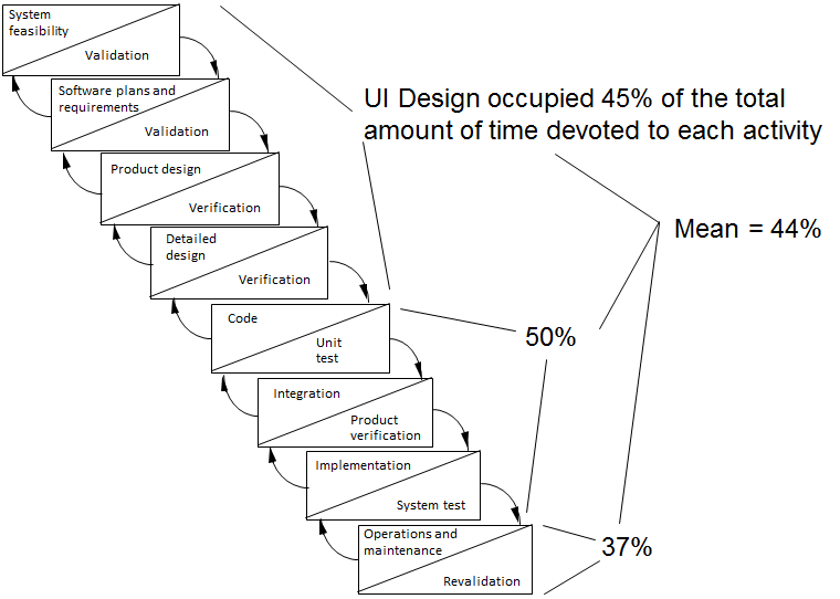
Figure 1. Distribution of UI development effort
in a waterfall development life cycle.
Today, developers of UI for interactive systems have to
address multiple sources of heterogeneity:
- Heterogeneity of end users: an interactive system is
normally used by several different end users. End users differ
with respect to their preferences, capabilities, culture (e.g.,
speaking different languages) and level of experience.
- Heterogeneity of computing platforms, interaction
modalities, input/output capabilities: there is a large
diversity of computing platforms (e.g., smartphone, desktop PC,
tablet, embedded devices) using different input capabilities
(e.g., keyboard, mouse, (multi-)touch, data gloves, motion
sensors, monitors, head-mounted displays) with different
interaction modalities (e.g., graphics, speech, haptics,
gesture, Brain-Computer-Interaction).
- Heterogeneity of programming/markup languages and widget
toolkits: for developing a UI, developers use different
programming/markup languages (e.g., Java, C++, HTML) with
different widget libraries (e.g., Swing, Qt, GTK+).
- Heterogeneity of working environments: many workflows in
the real world are supported by interactive systems through the
pervasiveness of computing devices. As a result, developers
have to consider different contextual constraints (e.g., noisy
environments, mobility).
- Variability of the context of use (<user, platform,
environment>). In addition to being heterogeneous, the
context of use dynamically evolves, calling for plastic UIs,
i.e. UIs capable of adaptation while preserving human values
(Thevenin and Coutaz, 1999). The dimensions that characterize
UI plasticity are presented in
The Problem Space of UI adaptation, UI Plasticity.
Model-Based User Interface Development (MBUID) is one approach
that aims at coping with the above mentioned challenges and at
decreasing the effort needed to develop UIs while ensuring UI
quality. The purpose of Model-Based Design is to identify
high-level models that allow designers to specify and analyse
interactive software applications from a more semantic oriented
level rather than starting immediately to address the
implementation level. This allows them to concentrate on more
important aspects without being immediately confused by many
implementation details and then to have tools which update the
implementation in order to be consistent with high-level
choices.
For a comprehensive overview of the history and evolution of
MBUID, we refer to (Meixner, Paternó, and Vanderdonckt, 2011).
Different frameworks have been developed to conceptually capture
the important aspects of a MBUID process. As early as 1996,
Szekely introduced a generic architecture for MBUID (Szekely,
1996). In 2000, Da Silva described an architecture for UI
development using a MBUID approach (Da Silva, 2000). The first
version of a reference framework for multiple contexts of use UIs
in history using a model-based approach, appeared in (Calvary et
al., 2001). This version was then extended with additional
relationships and definitions to give rise to a revised reference
framework published for the first time in July 2002 (Calvary et
al., 2002) and in (Calvary et al., 2003). It was then named the
Cameleon Reference Framework (CRF) when accepted as a new
deliverable of the EU-funded FP 5 CAMELEON project, published in
September 2002 (Calvary et al., 2002b). CRF has now become widely
accepted in the HCI Engineering community as a reference for
structuring and classifying model-based development processes of
UIs that support multiple contexts of use. CRF covers both the
design time and run time phases. In (Calvary et al., 2003)
metamodels and the use of models at runtime are proposed for
supporting UI plasticity.
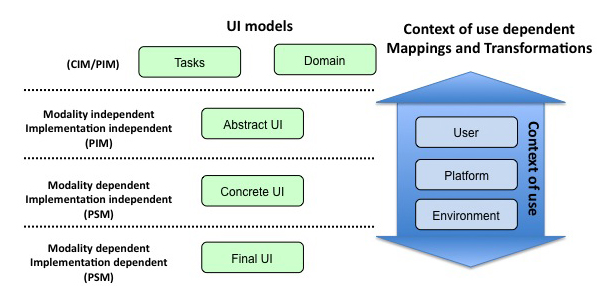
Figure 2. A simplified version of the Cameleon
Reference Framework (CRF). Mappings and transformations between
levels of abstraction depend on the context of use.
As depicted in Figure 2, the CRF makes explicit a set of UI
models (e.g., Tasks, Abstract UI, Concrete UI, Final UI) and
their relationships, to serve as a common vocabulary within the
HCI Engineering community to discuss and express different
perspectives on a UI.
- The Task and Domain models correspond to the hierarchies of
tasks that need to be performed on/with domain objects (or
domain concepts) in a specific temporal logical order for
achieving users’ goals (during the interaction with the UI).
Using the wording of the OMG Model-Driven Architecture (MDA) in
Software Engineering (http://www.omg.org/mda/), the
Task and Domain level is either a Computing Independent Model
(CIM) or a Platform Independent Model (PIM).
- The Abstract UI (AUI) model expresses the UI in terms of
Abstract Interaction Units (AIU) (or Abstract Interaction
Objects (AIOs) (Vanderdonckt and Bodart, 1993)), as well as the
relationships among them. These AIUs are independent of any
implementation technology or modality (e.g., graphical, vocal,
gestural). They can be grouped logically to map logically
connected tasks or domain objects.
- The Concrete UI (CUI) model expresses the UI in terms of
Concrete Interaction Units (CIU) (or Concrete Interaction
Objects (CIOs) (Vanderdonckt and Bodart, 1993)). These CIUs are
modality-dependent, but implementation technology independent,
thus platform specific (PSM). The CUI concretely defines how
the UI is perceived and can be manipulated by end users.
- The Final UI (FUI) model expresses the UI in terms of
implementation technology dependent source code. A FUI can be
represented in any UI programming language (e.g., Java UI
toolkit) or mark-up language (e.g., HTML). A FUI can then be
compiled or interpreted.
The relationships between the CRF models include (Bouillon and
Vanderdonckt, 2002): concretization, abstraction, translation,
and reflexion.
- Concretization is an operation that transforms a particular
model into another one of a lower level of abstraction, until
executable/interpretable code is reached. CRF shows a four-step
concretization process: the Task and Domain level (task model
and/or the domain model) is “concretized” into an Abstract UI
model, which in turn leads to a Concrete UI. A Concrete UI is
then turned into a Final UI, typically by means of code
generation techniques.
- Abstraction is an operation that transforms a UI
representation from any level of abstraction to a higher level
of abstraction. Reverse engineering of user interfaces is a
typical example of abstraction.
- Translation is an operation that transforms a description
intended for a particular context of use into a description at
the same level of abstraction, but aimed at a different context
of use.
- Reflexion is an operation that transforms a model into
another one at the same level of abstraction for the same
context of use (as opposed to different contexts of use as for
translation).
The aforementioned relationships always preserve some
dimension, either vertically (i.e., concretization and
abstraction) or horizontally (i.e., translation, reflexion). In
order to address non-horizontal/vertical transformations,
Cross-cutting (Limbourg and Vanderdonckt, 2009) is a
transformation of a model into another one at a different level
of abstraction (higher or lower), while changing the context of
use.
Orthogonal to the Task-Domain, AUI, CUI and FUI models, CRF
makes explicit the context of use that may have an impact on the
nature of the transformations used in the transformation process.
The term “context of use” denotes an information space structured
into three main models (see right side of Figure 2):
- The user model includes attributes and functions that
describe the archetypal person who is intended to use, or is
actually using, the interactive system (e.g., profile,
idiosyncrasies, current tasks and activities).
- The platform model includes an integrated collection of
software and/or hardware technologies and/or resource
specifications that bind together the physical environment with
the digital world.
- The environment model includes spatio-temporal attributes,
rules, and functions that characterize the physical and social
places when/where the interaction will take place, or is
actually taking place. This includes numeric and/or symbolic
times and locations (e.g., in the morning, at 4 o’clock, at
home, in a public space, on the move in the street, in the
train or car), light and sound conditions, social rules and
activities (e.g., hierarchical social organization, roles,
spatial and temporal relationships).
Although context of use is mainly defined based on information
about users, platforms, and environments, there are also other
dimensions that can be relevant to characterize context and to
properly adapt an interactive system. The application domain, for
instance, can also add relevant information that complete the
characteristics of the context of use. For example, in a safety
critical environment, knowing that the interactive system
supports air traffic control or a nuclear power plant provides
useful information about the level of attention that is required
from end users.
Unlike the process initiated in the 1980s, which contained one
entry point only at a high level of abstraction, CRF enables
entry and exit points at any level of abstraction from which any
combination of horizontal and vertical bottom-up and top-down
transformations can be applied. This theoretical flexibility
means that the stakeholders involved in the development of an
interactive system can use the development process (e.g.,
human-centered development processes according to ISO 9241-210)
that best suits their practice or the case at hand. Even when
using a top down approach, developers can explore multiple
development paths in parallel as illustrated in Figure 3.
However, due to this high flexibility, developers have to ensure
that models are not manipulated “by hand” after a transformation
has been done. If so, developers have to ensure model consistency
by e.g., using reverse transformations from a more concrete level
to a more abstract level.
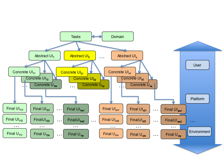
Figure 3. One example of possible
transformations across the levels of CRF according to different
contexts of use, starting from a unique Task and Domain
Model.
Benefits from using Model Based UI
Development
This section provides a list of potential benefits that are
usually discussed for model-based development and Model-Driven
Engineering (MDE) in general. Each potential benefit is then
refined in the context of UI development. General MDE benefits
are reported in (Hutchinson et al., 2011).
1. Benefits resulting from the existence of a step-wise
development life cycle:
- Reducing the gap between requirements and implementation: a
modelling phase aims to ensure in advance that the
implementation addresses the user-centered requirements. MBUID
contributes to this by explicitly defining models related to
the UI that are captured and updated throughout the development
life cycle. The output of a development step could serve as an
input for a next development step. Among typical models are the
task model, the domain model, the context of use model, thus
promoting a user-centered development life cycle (as
recommended by ISO 9241-210). These models are often, but not
always, specified according to declarative programming, a
programming paradigm in which the logic of the UI is described
without describing its control flow. Other programming
paradigms (e.g., logic programming, functional programming,
imperative/procedural programming) are also used individually
or mixed together (Grolaux, Van Roy, Vanderdonckt, 2001).
- Coordinating the involvement of multiple stakeholders:
previous planning of the development life cycle enables various
stakeholders (e.g., project leaders, designers, developers,
testers, end users, psychologists, marketing people) to
coordinate their work, e.g., by dividing the interactive system
into several parts and defining mappings between them.
Separation of concerns supports capturing various UI aspects in
independent, but possibly correlated, models thus enabling
these different stakeholders to fulfill their respective
roles.
- Producing well-structured systems: the stepwise development
life cycle together with the separation of concerns provide a
good basis for producing a well-structured system, thus
facilitating implementation itself as well as maintenance.
2. Benefits resulting from the use of explicit abstract
models:
- Planning an adequate level of abstraction: modeling
languages provide the developer with concepts for planning and
reasoning about the developed system at the appropriate level
of abstraction. MBUID contributes to this benefit by defining
the levels of abstraction described in CRF.
- Improving communication by explicit models: the
explicitness of modeling languages, in particular their visual
representation, can lead to increased quality (e.g.,
understanding, perceiving, exploring, explaining, justifying,
comparing, etc.,) of design documents for all stakeholders. For
instance, MBUID contributes to this benefit by explicitly
defining semantics, syntax, and stylistics for each model.
- Supporting UI quality: (semi-)formal modeling languages
explicitly support UI compliance with respect to requirements
(e.g., UI quality factors, usability guidelines (Fernandez et
al., 2012), accessibility guidelines (e.g., WCAG), validation
rules for completeness, consistency, correctness).
3. Benefits from exploring alternative designs:
- Supporting creation & creativity: MBUID efficiently
produces alternative models with different design options,
parameters, thus fostering the exploration of the design space
(Masson, 2010).
- Enabling the production and comparison of alternative
designs for multiple contexts of use while preserving quality
(e.g., consistency): when UIs need to be produced for multiple
contexts of use, MBUID facilitates the rapid production and
comparison of alternative designs (e.g., factoring out common
parts that are context-independent from specific
context-dependent parts), which is particularly useful in
change management (Pilemalm et al., 2012).
4. Benefits resulting from code generation: the benefits
associated with this appear when the method is enacted.
- Enhancing development productivity: code generation from a
set of models often requires only a small fraction of time
compared to the manual production of code. Consequently, MBUID
favors UI rapid, iterative, agile development, including UI
mockups and prototypes at different levels of fidelity
(Coyette, Kieffer, Vanderdonckt, 2007).
- Capturing and reusing expert knowledge throughout UI
development life cycle: expert knowledge – e.g., about user
interface design, usability engineering, code structuring, code
optimizations, or platform-specific vs platform-independent
features – once incorporated in various development steps,
expert knowledge can then be reused by all stakeholders
(especially developers and designers).
- Reducing errors: automatic transformation avoids manual
errors. “Integranova creates customised solutions in half the
time, personalised solutions for half the price, and
top-quality, error-free software.” (Integranova, 2012).
5. Benefits from using models at runtime:
- Considering contexts of use that were not envisioned at
design time: when a new context of use needs to be considered
(e.g., opportunistic end users needs), then models can be
exploited at runtime to support on the fly adaptation (Garcia
Frey, 2012).
- Explaining and justifying the UI to the end user: the UI is
able to explain and to justify itself to the end user thanks to
the models that capture the design rationale and that are
embedded at runtime (Garcia Frey, 2013).
- Going beyond low level adaptation: adaptation can span from
the highest level of abstraction (e.g., the task and the domain
models) to the lowest level (e.g., the final UI).
- Enabling UI evolution. When requirements continuously
evolve at run time, the UI should be repeatedly modified, and
so do its models, as well as the design knowledge used to
produce it. This evolution could be governed by the user (i.e.,
manually by the way of a meta-user interface (Coutaz, 2006)),
by the system (i.e., autonomously as in autonomic computing
(IBM, 2001)) or by both (i.e., mixed-initiative
(Models@run-time, 2009; Eisenstein and Puerta, 2000; Mitrovic
et al., 2007)).
6. Benefits for supporting method engineering:
- Defining and enacting method for UI development process:
once defined, a method could be enacted and any deviation with
respect to the definition could be pointed out.
- Knowledge about creation of modeling languages: MDE
concepts and definitions reflect existing knowledge about
modeling, modeling languages, and code generation. MBUID
contributes to this benefit by bringing expertise about models
for user interface development.
- Usage of frameworks and tools: various software tools, such
as Integrated Development Environments (IDEs), could support
MBUID. In more advanced model-driven engineering of UIs, tools
exist that support MDE steps, such as creating and processing
metamodels, creating modeling editors, and defining and
executing transformations (e.g., transformation engines).
7. Maintenance of modeling language and transformations:
- Systematic and explicit definition of metamodels and
transformations: when all models and transformations are
defined according to a common set of meta-models, their usage
becomes systematic. This also works for MBUID.
- Maintenance of modeling languages and code generators:
modeling languages, associated model-to-model transformations
and model-to-code compilation can be maintained at a level of
expressiveness that is higher than a traditional programming or
markup language.
- Reuse of models, metamodels, and transformations: MDE
compliant metamodels and transformations can be understood and
reused by others. Models or model fragments could be reused
from one use case to another or from one context of use to
another, only affecting the portion that is subject to change
(Pilemalm et al., 2012). This reuse facilitates the development
of plastic user interfaces (Seffah and Javahery, 2004).
Use Cases for Model-Based UI Design
This section provides a list of implemented use cases to
illustrate different CRF-compliant development processes. Table 1
provides a synthetic view of the differentiating characteristics
of these exemplars where lines refer to the level of abstraction
used as the entry point from which transformations are performed,
and where columns indicate whether these transformations are
performed at design time or at run time. The document
Complementary List of Use Cases provides additional
examples.
|
Entry Point / Software Life Cycle Phase
|
Design Time
|
Run Time
|
|
Task & Domain
|
UC1 - Car Rental
UC2 - Digital Home
|
UC3 - Minimalistic UIs
|
|
Abstract UI
|
UC4 Story Editor
|
UC5 - Post WIMP Widgets
|
|
Concrete UI
|
UC6 - Automotive Industry (Infotainment system
design)
|
UC7- Photo-Browser
|
|
Final UI
|
|
UC8 - Tourism Web Site (TWS)
|
1. Car Rental System
Responsible:
- Université catholique de Louvain (Jean Vanderdonckt, Vivian
Genaro Motti, Pascal Beaujeant, Nesrine Mezhoudi)
1.1 Introductory Description
The car rental example consists of a scenario in which the
interactive system permits users to rent a car. In this sense,
various contextual information can be used to adapt application
aspects, and to properly display the list of cars to rent,
enabling users to make choices and to accomplish the main
task.
The key functional requirements to support this task include
the capacity to:
- specify the pick-up and return locations of the car;
- specify the period for the car rental;
- access a set of possible cars and select one;
- access and select additional car features (e.g. GPS);
- provide personal information before renting the car;
- access details about the car rental before making the final
decision.
Two contexts of use are targeted:
1) Context 1: Physical environment is that of a home, platform
is a Desktop PC, and the user is an English speaker who does not
know the city where the car has to be rented.
2) Context 2: Physical environment is a busy street, platform
is a smartphone, and the user is walking fast (busy eyes).
Figures UC1.1 and UC1.2 show screenshots for the two targeted
contexts of use.
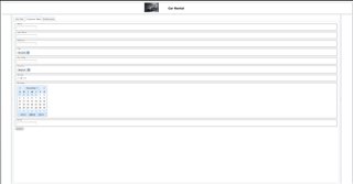
Figure UC1.1. A Concrete User Interface for
Context1 “Home, PC, English speaker familiar with the
location”.
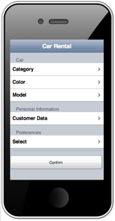
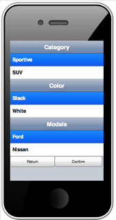
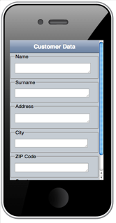
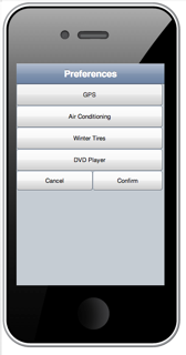
Figure UC1.2. A Concrete User Interface for
Context2 “Noisy street, SmartPhone, English speaker walking fast,
not familiar with the location”.
1.2 Diagram and Discussion
Figure UC1.3 illustrates how a MBUI approach can be applied
using successive concretization transformations starting from a
single Task and Domain Model to different Abstract User
Interfaces (each one corresponding to a specific context of use)
and iteratively down to Final User Interfaces.
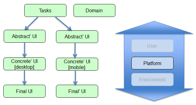
Figure UC1.3. Models involved in the car rental
use case and the process.
Figure UC1.4. Task models for the two targeted
contexts of use.
2. Digital Home
Responsible:
- CNR-ISTI (Fabio Paternò, Carmen Santoro, Lucio Davide
Spano)
2.1 Introductory Description
Digital home refers to a residence with devices that are
connected through a computer network. A digital home has a
network of consumer electronics, mobile, and PC devices that
cooperate transparently. All computing devices and home
appliances conform to a set of interoperable standards so that
everything can be controlled by means of an interactive system.
Different electronic services can be offered by a digital home
system, including but not limited to e.g., manage, synchronize
and store personal content, family calendars and files; upload,
play and show music, videos and pictures on a home screen (e.g.,
a TV) using a mobile phone as a remote control; use a mobile
phone as a remote control for the other devices, for example a
thermostat.
These functionalities are made available through context
sensitive user interfaces. In fact, such UIs are capable of
adapting to different computing platforms (touch-based devices,
web, mobile, TV, PDA, DECT handset, voice portal …), users
(children, teenagers, adults, elderly, disabled people, …) and
environments or situations (at home, away, at night, while music
is playing, …). The final aim is to provide a seamless and
unified user experience, which is critical in the digital home
domain. To this regard, different automatic UI adaptations can be
possible: e.g., zooming the UI if the user has visual problems;
enabling multimodal interactions (ex. voice interaction) because
the user is doing another task at the same time.
The key functional requirements for this application are the
following:
- authenticate a user in order to enable remote access to
home devices
- select a room
- select a device inside the room
- inspect and modify the status of a selected device
This application may be used in different contexts of use:
1) Context 1: Physical environment is that of a home, platform
is a Desktop PC, and the user controls the home devices without
accessing directly the physical controls.
2) Context 2: Physical environment is a street, and the user
is moving. The user controls the home devices remotely, in order
to e.g. start heating the home before coming back.
In this use case, the context dimension considered is limited
to the platform aspect.
Figures UC2.1 and UC2.2 show screenshots of the Digital Home
for two targeted contexts of use.
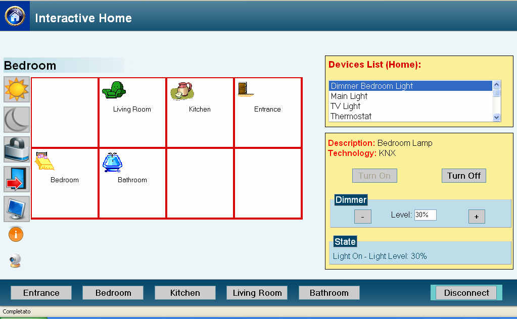
Figure UC2.1: The desktop version of the
Digital Home application.
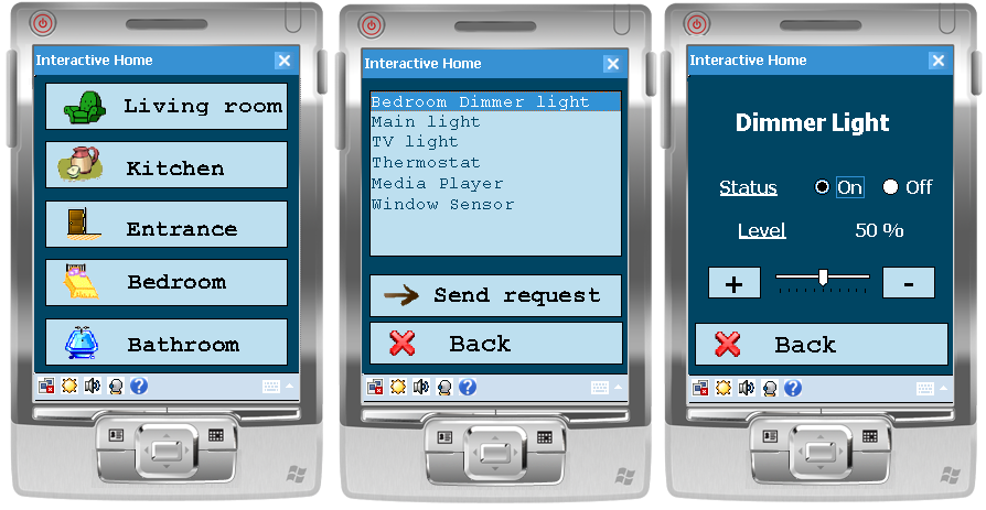
Figure UC2.2: The mobile version of the Digital
Home application.
2.2 Diagram and Discussion
The models involved in the Digital Home use case as well as
the process involving them are depicted in Figure UC2.3.
Figure UC2.3. Models involved in the Digital
Home use case and the process.
The use case considered in the Digital Home exemplar (Mori et
al., 2008) starts from the task model shown in Figure UC2.4.
Because we consider the platform as the only dimension of the
context of use, the other context aspects have been greyed out in
Figure UC2.3. From the task model, it is possible to derive an
Abstract UI for each targeted context of use. Let’s consider a
desktop PC. On the one hand, this AUI will be expressed using a
modality and platform -independent vocabulary (also shared by
other AUIs addressing different computing platforms), on the
other hand, this AUI will include only the abstract interaction
units that make sense in that considered computing platform (a
desktop PC). From this AUI, it is possible to obtain a Concrete
UI and then a Final UI in a specific implementation language
suitable for that computing platform. A similar process is
followed to obtain a Final UI for a different platform (e.g., the
mobile one). From the filtered CTT task model, an Abstract UI is
derived and then a CUI and finally an implemented UI expressed in
a language supported by the mobile platform is built.
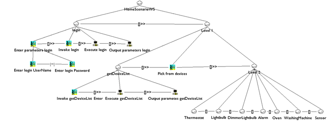
Figure UC2.4. The Task Model for the Digital
Home.
3. Omitting minimalistic UIs through the
use of an universal interaction device in production
environments
Responsible:
- Heilbronn University (Gerrit Meixner)
- DFKI (Marc Seissler):
3.1 Introductory Description
The SmartFactoryKL (see Figure UC3.1) is an arbitrarily
modifiable and expandable (flexible) intelligent production
environment, connecting components from multiple manufacturers
(networked), enabling its components to perform context-related
tasks autonomously (self-organizing), and emphasizing
user-friendliness (user-oriented). The SmartFactoryKL is the
first ambient intelligent production environment for
demonstration and development purposes worldwide. Development of
user interfaces is a secondary field in the production industry,
but the impact of user interface quality is increasingly
independent of the application domain, which is a significant
factor of success for the entire product. After three years of
research, a first prototype has been finished that allows for
controlling the production line using a single universal
interaction device able to adapt to varying field devices
according to the actual context of use, in a complex, model-based
approach. To handle the resulting diversity of user interfaces,
we developed a universal interaction device – the SmartMote –
which is capable of providing control over various devices in
these environments. Depending on the context of use, the
visualization of the SmartMote is generated and adapted during
run-time in order to provide a homogeneous intra-device user
experience.
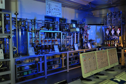
Figure UC3.1. The SmartFactoryKL
The key functional requirements for this application are the
following:
- authenticate a user in order to enable remote access to
modules or field devices
- select a module or a field device
- inspect and interact (e.g. modify parameters) with a
selected module or field device
The SmartMote may be used in one context
1) Context 1: Physical environment is that of a production
environment (industrial factory), platform is a tablet PC (+
modules or field devices from different vendors), one single
user
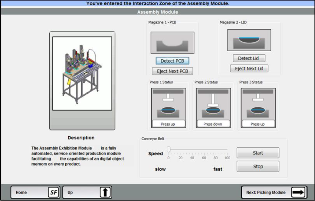
Figure UC3.2. Screenshot of a rendered (final)
UI with the SmartMote (Seissler, 2013)
3.2 Diagram and Discussion
For the specification of the context-sensitive UI a
model-based architecture has been developed that consists of two
core models (AUI-model and CUI-model). The AUI-model is specified
using the “Useware Dialog Modeling” Language (useDM) that enables
the abstract, modality-independent specification of the user
interface. This model is refined via a CUI-model that uses the
User Interface Markup Language (UIML) 4.0 for the
platform-independent description of the graphical user interface.
Adaptation rules are further used to specify the adaptation that
can be applied on those models at run-time. To generate the final
user interface (FUI) a java-based Renderer – SmartMote – has been
developed.
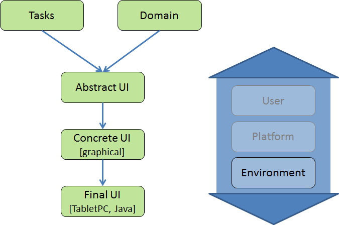
Figure UC3.2. Models involved in the
Minimalist-UI use case and the process.
4. Story Editor
Responsible:
- University ‘“La Sapienza” of Rome (Paolo Bottoni)
4.1 Introductory Description
The production of e-learning tools for deaf people meets with
several difficulties, connected to the need to resort only to the
visual channel, without saturating it, and to the adoption of
different cognitive strategies developed within the community.
From a field study conducted with deaf people in the context of a
national project involving cognitive scientists, linguists, and
computer scientists, we adopted the metaphor of a learning story
as the basis for organising different types of learning material:
videos, pictures, texts, accompanied by translation in the
Italian Sign Language. We report on the use of a user interface
abstract model in the development of the interactive story
editor, to be used by tutors and teachers to organise the course
material and path, and which generates interactive pages for the
students.
The key functional requirements to support developers of
course include:
- specify the activities involved in a learning module;
- specify the logical paths according to which these
activities can be performed;
- specify the conditions for progressing along these
paths.
The context of use is that of the generation of a course by a
teacher, possibly involving in the process tutors who will then
have to assist the learners. Learners and tutors will then
interact with the generated web pages (Bottoni et al., 2012).
The development relies on an abstract model of the learning
domain, in which stories are seen as workflows: (learning)
processes in which tasks are assigned to actors (e.g., students
and tutors). Stories can be recursively composed by sub-stories,
paths define sequences or alternatives for exploration of
stories, with transitions connecting sub-stories, and tasks
either are defined as simple stories to be explored individually
or in a laboratory, or require the exploration of sub-stories.
Each story has a single entry point and a single exit point,
signalling completion by the student.
Stories are classified with respect to the exploration
strategy and associated with abstract patterns. For example, in a
star topology tasks can be performed in any order. For each type,
the story editor provides a specialised form of interaction,
guiding the teacher to define the story according to that type,
and a template is used to generate the appropriate main page for
the story accordingly. Figure UC4.1 (left) presents the workflow
for a story with three sub-stories organised in a star topology.
Figure UC4.1 (right) shows the generated page for a story with
star topology providing access to five sub-stories. The lateral
bars are generated according to a general template.
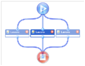
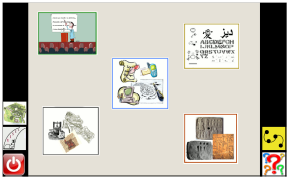
Figure UC4.1: The workflow for a star-story
(left) and a generated page for a star-story (right).
4.2 Diagram and Discussion
The models involved in the Digital Home use case as well as
the process involving them are depicted in Figure UC4.2.
The design of the interaction with the Story Editor and of the
templates for the generated pages derives from the representation
of tasks in the form of patterns composed by specific task trees.
For each pattern, the story editor will constrain the interaction
to create instances of that pattern, and will generate the
specific workflow to be followed while interacting with the
generated page. Moreover a corresponding pattern of interaction
elements to be included in the generated page is provided as an
abstract user interface model.
The target platform is that of Web pages with associated
JavaScript components for the interaction with the specific
learning content.
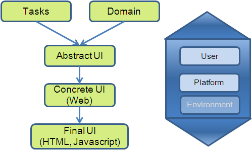
Figure UC4.2. Models involved in the Story
Editor use case and the process.
As shown in Figure UC4.3, a StoryContainer will present
several individual components, providing context for the
interaction, and a PresentationContainer, composed of several
different “page contents” in a mutual emphasis relation so that
they cannot be shown together). The specific composition of the
presentation container will depend on the type of story to be
presented, as prescribed by the Task Model, where either an
individual component or a container is associated with each
task.
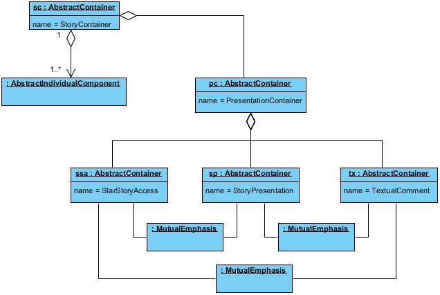
Figure UC4.3: The overall abstract structure of
story containers.
5. Post – WIMP Widgets
Responsible:
- OFFIS e. V. (Sebastian Feuerstack)
5.1 Introductory Description
With the introduction of technologies like HTML5, CSS3, and
SVG, the way people can interact with the web has been
fundamentally enhanced. Designers are no longer required to use a
predefined set of basic widgets. Instead, interaction can
nowadays be driven by self-designed widgets specifically targeted
at some specific user needs or specific application requirements.
These Post-WIMP widgets are designed to support different
combinations of modes and media and can guarantee a certain
quality-in-use upon context changes. Based on ubiquitous
availability of browsers and corresponding standardized W3C
technologies Post-WIMP widgets can be easily designed and
manipulated (e.g. SCXML, ECMA), instantly reflect continuous
context changes (e.g. by WebSockets) and consider different
multimodal setups (e.g. XHTML+Voice, SMIL, and the
MMI-Architecture).
The fact that the control and appearance of Post-WIMP widgets
is designed with a high degree of freedom has an impact on MBUID
approaches: the toolkit and therefore the target of a model
transformation can no longer been assumed as static (a fixed set
of widgets). The same models (task model, AUI model, CUI model)
known from MBUID can be applied to design individual Post-WIMP
interactors. Additionally, a statechart-based behavior
description captures the enhanced interaction capabilities of a
Post-WIMP interactor. As an example we consider two use-cases of
Post-WIMP interactors running inside a web application: A mixed
reality furniture online shop that can be controlled by gestures
and supports inter-reality migration of interactors and an
interactive music sheet that can be controlled by head
movements.
Web Furniture Shop
In the web furniture shop, a customer can choose between
different furniture and fill up a shopping cart. By a
drag-and-drop gesture using both hands one can drag furniture
interactors virtually out of the monitor displaying the web shop
and drop them into an augmented reality to see if the furniture
really matches in space and color to the user’s environment. An
augmented reality frame that surrounds the shopping cart allows
to seamlessly switch between realities while crossing it during
the drag and drop gesture.
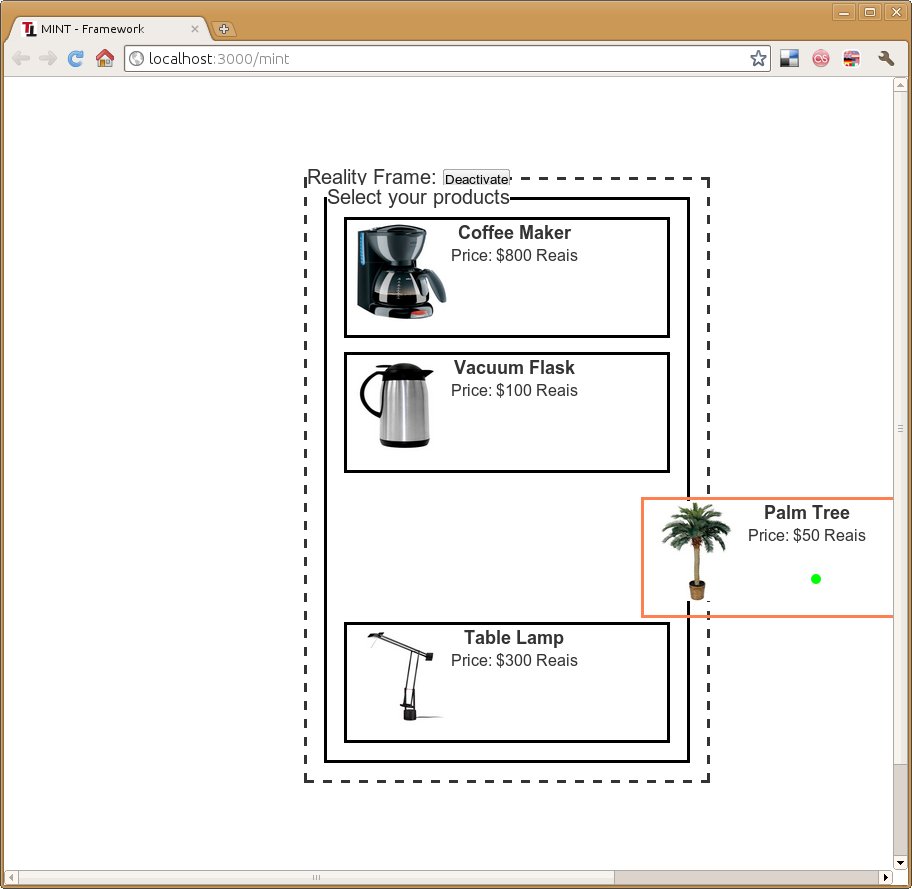
Figure UC5.1: Shopping cart web application
with reality frame.
Figure UC5.1 shows the actual shopping cart that is part of a
typical online shop and has been enhanced by a Reality Frame. To
enable a reality crossing Drag-and-Drop, the Reality Frame needs
to be activated, which triggers a calibration of the system that
identifies the monitor’s physical location in the environment of
the user using a camera and a visual marker.
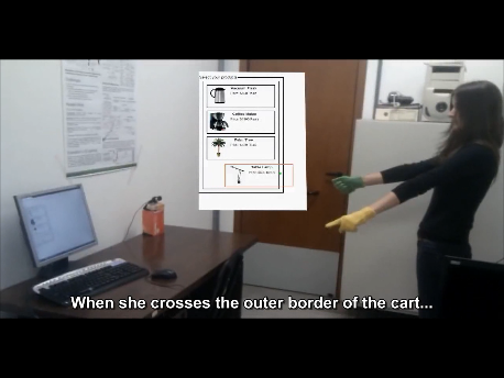
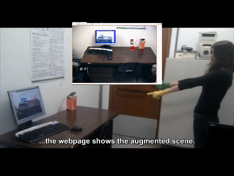
Figures UC5.2a(left) and UC5.2b (right): Two
handed gesture to pick and drop furniture.
Figures UC5.2a and UC5.2b depict a user dragging furniture
using the left hand for pointing and the right hand for picking
up an object in the browser. After the users has crossed the
reality frame of the shopping cart in the browser, the web page
changes to the augmented scene enabling her to position the
furniture in her own environment.

Figure UC5.3: Using a mouse to drag and drop
furniture into the environment of the user.
Figure UC5.3 shows an adaptation of the interactors that
support the same interaction using a classical mouse and keyboard
setup.
The key functional requirements for support the user of the
online furniture shop include:
- choose and add furniture to shopping cart
- drag furniture items out of the website
- drop furniture items into the augmented environment of the
user
Three contexts of use are targeted:
- Physical environment is the home of the user, platform is a
desktopPC to be controlled by a mouse, and user is the online
shop customer
- Physical environment is the home of the user, platform is a
desktopPC to be controlled by an interaction technique that
requires hand gestures with both hands.
- Physical environment is the home of the user, platform is a
desktopPC to be controlled by an interaction technique that
requires hand gestures using just one hand.
Interactive Music Sheet
When learning to play a musical instrument, or when playing
one, a music sheet is used to give guidance as to how to perform
the musical piece. However, as songs become longer and more
intricate they may span across several sheets, forcing the player
to stop playing to turn the page. Although this may become easier
as one becomes more experienced with the instrument, it is a
barrier for inexperienced players that can be tackled easily
using a different mode to turn the pages other than your
hand.
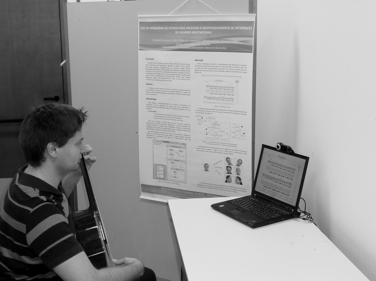
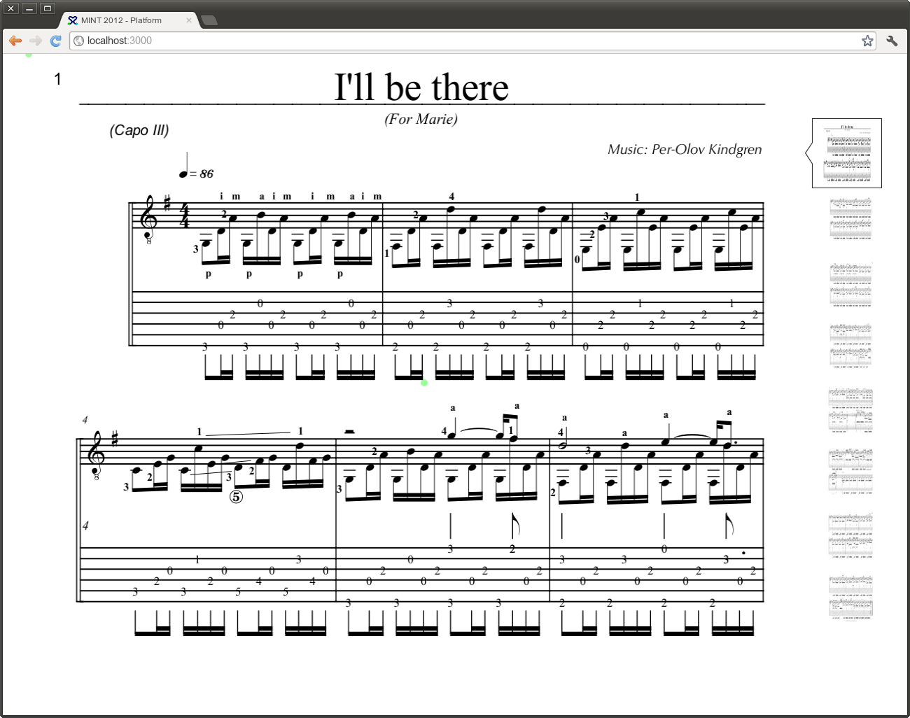
Figure UC5.4 (left): Music sheet control setup
Figure UC5.5 (right): Music sheet web application
We propose a UI to turn music sheets with simple head
movements that can be captured by a basic VGA webcam, a common
part of modern notebooks. The considered setup is shown in Figure
UC5.4 and a screenshot of the web browser displaying the music
sheet is depicted in Figure UC5.5.
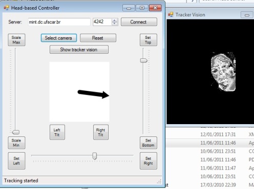
Figure UC5.6: Head Tracking Interactor
A head movement mode interactor supports detecting tilting the
head to the side, right and left, as the controller to pass to
the next page or return to the previous page, respectively.
Figure UC5.6 shows a screenshot of the head tracker. The left
side of the figure shows the debugging user interface in that a
moving arrow represents the direction of the head movement
(mirrored).
The key functional requirements for support the user of the
online furniture shop include:
- Turn music sheet pages triggered by various head
movements
Three contexts of use are targeted:
- Physical environment is the home of the user, platform is a
desktopPC to be controlled by an interaction technique that
involves tilting the head to the left and to the right.
- Physical environment is the home of the user, platform is a
desktopPC to be controlled by an interaction technique that
involves turning the head to the left and to the right.
- Physical environment is the home of the user, platform is a
desktopPC to be controlled by an interaction technique that
requires nodding.
5.2 Diagram and Discussion
The process starts at the final user interface and identifies
interface elements (widgets) that should be enhanced to be
controllable via various modalities, e.g., gestures or body
movements. For each FUI element, a mapping is then defined that
identifies the abstract Interface interactor (from a pre-existing
abstract interactor model - http://www.multi-access.de/mint/aim)
that matches best the behavior of the FUI element. Then, concrete
user interface interactors are specified that represent the FUI
element’s behavior as a model (by a state chart). Finally, the
modeled behavior is precisely mapped to the Final UI element
(http://www.multi-access.de/mint/mim).
Further control modes or interactor representing media that
have been derived from the same AUI interactor and for that
already CUI model interactors have been defined can then be used
as an additional control mode or representation for the new FUI
element (http://www.multi-access.de/mint/irm)
(Feuerstack, 2012a).
Different to the other approaches the main intention of the
process is to identify and specify interactors on the abstract,
concrete and final user interface level to form an interactor
repository of re-usable interface elements that synchronize
themselves over various control modes and media representations
(http://www.multi-access.de/mint-2012-framework/)
(Feuerstack2012b)
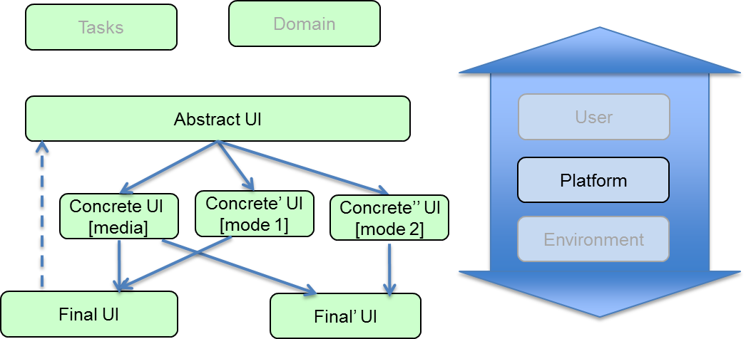
Figure UC5.7. Models used for the Post-WIMP widgets use case,
and the process.
6. UI development in the automotive
industry to handle UI varieties and to increase efficiency of UI
development processes
Responsible:
- CERTH/ITI (Nikolaos Kaklanis)
- DFKI (Marius Orfgen)
- Heilbronn University (Gerrit Meixner)
- Robert Bosch GmbH (Ran Zhang)
6.1 Introductory Description
Car infotainment systems are currently developed using huge
textual specifications that are refined iteratively while
parallel being implemented. This approach is characterized by
diverging specifications and implementation versions, change
request negotiations and very late prototyping with
cost-intensive bug fixing. Number and variety of involved actors
and roles lead to a huge gap between what the designers and
ergonomists envision as the final version, what they describe in
the system specification and how the specification is understood
and implemented by the developers.
Model-based user interface development could speed up the
iterative implementation while reducing implementation efforts
due to automatic generation of prototype interfaces. Different
models could be used to establish a formal and efficient
communication between designers, functionality specialists (e.g.
Navigation, Telephone and Media), developers and other
stakeholders. The resulting reduction of development time would
make car infotainment systems more competitive and would narrow
the gap to innovation cycles in the field of consumer
electronics.
Another large aspect of modern car infotainment systems is the
quality assurance that is performed by the vendors. The
complexity of modern infotainment systems (more than 1000
different screens and different modalities) requires large
efforts to develop formal test models on the basis of the system
specification. The test models are then used by the vendor to
test the implementation coming from the supplier. This procedure
results in another time and cost-intensive gap that could be
bridged by performing consistency checks on the models used to
generate the infotainment system instead of testing the
implementation.
Moreover, vehicles and their infotainment systems have to be
accessible. Even though model-based user interface development
could speed up the iterative implementation, a further step is
needed to enforce the accessibility of the cars: the description
of the user. If user-interface description languages can also
describe the user efficiently, including elderly and people with
disabilities, then the two definitions (UI & user) could be
used in frameworks performing automatic/simulated accessibility
evaluation of the prototype interfaces of a car.
The key functional requirements to support UI development in
the automotive industry include the capacity to:
- create a prototype UI of a car infotainment system
- view the prototype UI
- edit the prototype UI
- perform automatic functional testing of the prototype
UI
- perform automatic accessibility testing of the prototype UI
using user models (representing various population groups with
or without disabilities)
Two contexts of use are targeted:
1) Context 1: Physical environment is that of an automotive
company office, platform is a desktop PC and user is a
developer.
2) Context 2: Physical environment is that of an automotive
company office, platform is a Virtual Reality CAVE and user is a
designer.
6.2 Diagram and Discussion
The models involved in the automotive industry scenario, as
well as the process involving them, are depicted in Figure
UC6.1.
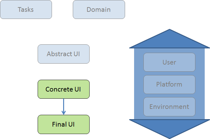
Figure UC6.1. Models used in the Automotive
Industry use case, and the process
In the automotive industry UIs are developed starting at the
CUI level. Normally developers start with sketches, mock-ups or
paper prototypes and iterate. On the basis of mock-ups
interaction and graphical designers refine the mock-ups to
wireframes and finally develop the graphical design e.g., with
Adobe Photoshop. In the end the prototypes are manually
transferred into a final UI for a specific infotainment system.
The project automotiveHMI (http://www.automotive-hmi.org/)
is developing a process and a UIDL to integrate the working
artifacts of the involved developers to generate the FUI
automatically.
7. Photo-Browser
Contributors:
- University of Grenoble (Joelle Coutaz, Gaëlle Calvary)
7.1 Introductory Description
Photo-Browser supports photo browsing in a centralized or
distributing way depending on the availability of a dynamic set
of interactive devices (http://iihm.imag.fr/demo/photobrowser/).
These include a multi-touch interactive table, a projected
display on a wall, an Android SmartPhone, and a kinect to track
gestures. As shown in Figure UC7.1, the UI of Photo-Browser is
dynamically composed of the following components: a Tcl-Tk
component running on the multipoint interactive surface (Fig.
UC7.1d), a component that transforms an HTLM-like CUI into HTML
code to serve as input to a Web browser (this code supports the
task “sequential navigation through the image portfolio”) (Fig.
UC7.1c), a Java component that provides a list of the photo names
(Fig. UC7.1b), and a Java component running on the SmartPhone to
navigate through the photos sequentially using the Next and
Previous buttons.
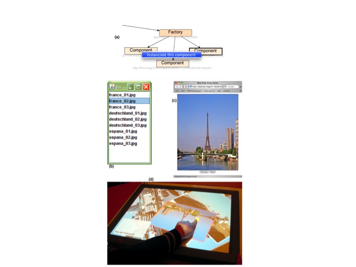
Figure UC7.1. Photo-browser: a dynamic
composition of executable and transformable components managed by
a dynamic set of interconnected factories (a) running on
different platforms (Windows, MacOS X, and Android).
When the user, say Alice, enters the room, the interactive
table starts automatically and shows Bob’s last opened photo
portfolio. By performing a “wipe” gesture from the table to the
wall, the current selected photo of the table is replicated on
the wall. As Alice brings her SmartPhone in contact with the
table, the phone can be used as a remote controller (Figure
UC7.2). Using a wipe gesture over the table provokes the table to
shut down. Alice can carry on her task using the wall as a large
display and the SmartPhone as a remote controller. Here, a
meta-UI has (Coutaz, 2006) been developed to support two classes
of functions: (a) Dynamic software deployment in the ambient
interactive space, and (b) UI redistribution across interactive
devices including on-the-fly generation from a CUI HTML-like to
native HTML code.
The key functional requirements to support UI migration for
photo-browser include the capacity to:
- specify the source picture,
- specify the target device where to display the source
content,
- add a device (e.g., SmartPhone)
- suppress a device (e.g., interactive table).
Four contexts of use are targeted:
1) Context 1: Physical environment is that of an office,
platform is an interactive table PC, one single user.
2) Context 2: Physical environment unchanged, platform is
composed of an interactive table and of a PC equipped with a
beamer, one single user.
3) Context 3: Physical environment unchanged, platform is
composed of an interactive table, a PC equipped with a beamer,
and a SmartPhone, and a single user
4) Context 4: Physical environment unchanged, platform is
composed of a PC equipped with a beamer, and a SmartPhone, and a
single user.
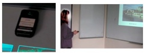
Figure UC7.2. (Left) Connecting a SmartPhone to
the interactive space by laying it down on the interactive table.
(Right) Using the SmartPhone as a remote-controller to browse
photos displayed by the HTML-based UI component of Figure UC7.1c
and video-projected on the wall.
In this scenario, “Alice entering the room” corresponds to a
situation that the Context Manager is able to recognize: “it is
User Alice and Alice has entered Room Ambient Space”. The action
that the Context Manager must perform has been specified earlier
by Alice using an end-user development tool (or has been learnt
automatically by the ambient space and confirmed by Alice). For
example, using a pseudo-natural language programming language,
Alice has instructed the context manager that “when I enter Room
Ambient Space, please start the table with my last opened photo
roll”. This sentence is then translated into an Architectural
Description Language (ADL) whose interpretation by a middleware
at runtime automatically deploys or stops the appropriate
software components.
The UI of the meta-UI includes the recognition of three
gestures: (1) a “wipe” gesture that allows the user to command
the migration of the current selected photo from the table to the
wall, (2) a “wipe” gesture that commands the system to shut down
the table, and (3) the contact of the SmartPhone with the
interactive table.
7.2 Diagram and Discussion
The diagram of Figure UC7.3 makes explicit the use of models
at runtime: full coverage of the context of use, and remolding
performed by on-the-fly transformation of one single component:
that of the HTML-like CUI to the native HTML code of the target
browser running on the PC. The other components are not
transformed but are meta-described and dynamically recruited as
resources of the platform.
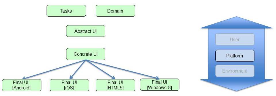
Figure UC7.3. Models used in the Photo-Browser
use case, and the process.
8. Tourist Web Site (TWS): Migratory UI
under Human Control
Contributors:
- University of Grenoble (Gaëlle Calvary, Joëlle Coutaz)
8.1 Introductory Description
The Tourist Web Site (TWS) provides tourists with information
for visiting and sojourning in the Sedan-Bouillon area, including
a selection of hotels, camping, and restaurants. The UI of TWS is
centralized when used from a PC workstation. Preparing a trip for
vacation is an exciting experience when shared by a group of
people (Figure UC8.1-left). However, one single PC screen does
not necessarily favor collaborative exploration. By dynamically
logging to the same website with a SmartPhone, users are informed
on the SmartPhone that they can distribute the UI components of
the site across the interaction resources currently available.
Using a form, the user asks for the following configuration: the
title of Web pages must appear on the SmartPhone as well as on
the PC (the title slots are ticked for the two browsers
available), whereas the content should stay on the PC whose
screen is projected on the wall, and the navigation bar should
migrate to the SmartPhone (Figure UC8.1-right). This form, which
allow users to reconfigure the UI of TWS is the user interface of
the meta-UI of the system (Coutaz, 2006).
The key functional requirements to support UI migration for
TWS include the capacity to:
- specify the intention to redistribute the UI,
- specify the source content elements of web pages,
- specify the target device where to display the source
content.
Two contexts of use are targeted:
1) Context 1: Physical environment is that of a home, platform
is a Desktop PC, one family member as a single user.
2) Context 2: Physical environment is that of a home, platform
is composed of a Desktop PC and of a SmartPhone, family members
as users.
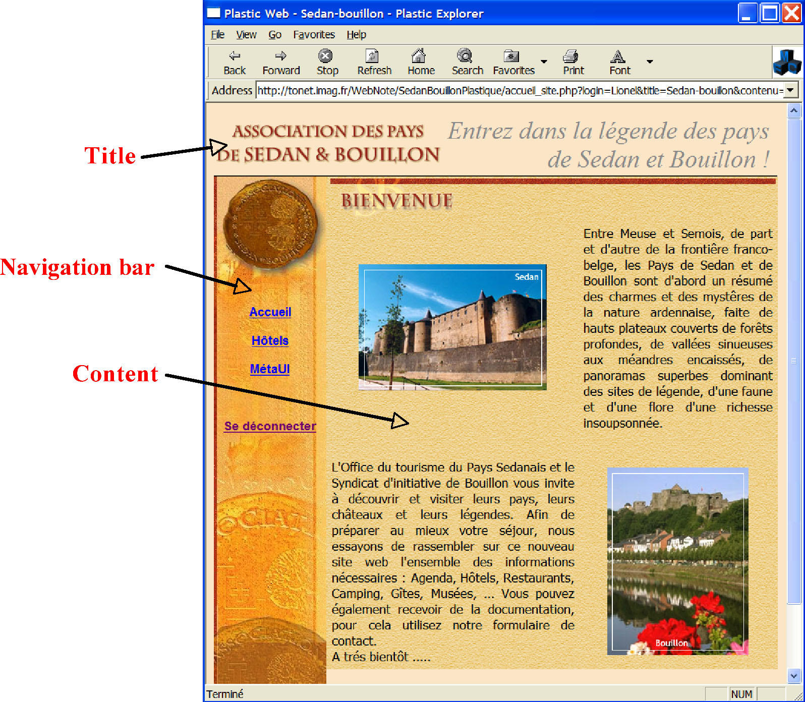
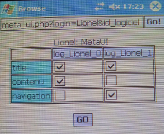
Figure UC8.1. The TWS web site. UI centralized
on a PC screen (left). The control panel of the meta-UI to
distribute the presentation units across the resources of the
interactive ambient space (right). The lines of the matrix
correspond to the pieces of content that can be redistributed,
and the columns denote the browsers currently used by the same
user.
At any time, the user can ask for a reconfiguration of the UI
by selecting the “meta-UI” link in the navigation bar (Figure
UC8.2). The UI will be reconfigured accordingly. In this example,
the function supported by the meta-UI is UI redistribution using
a typical form-based interaction technique.
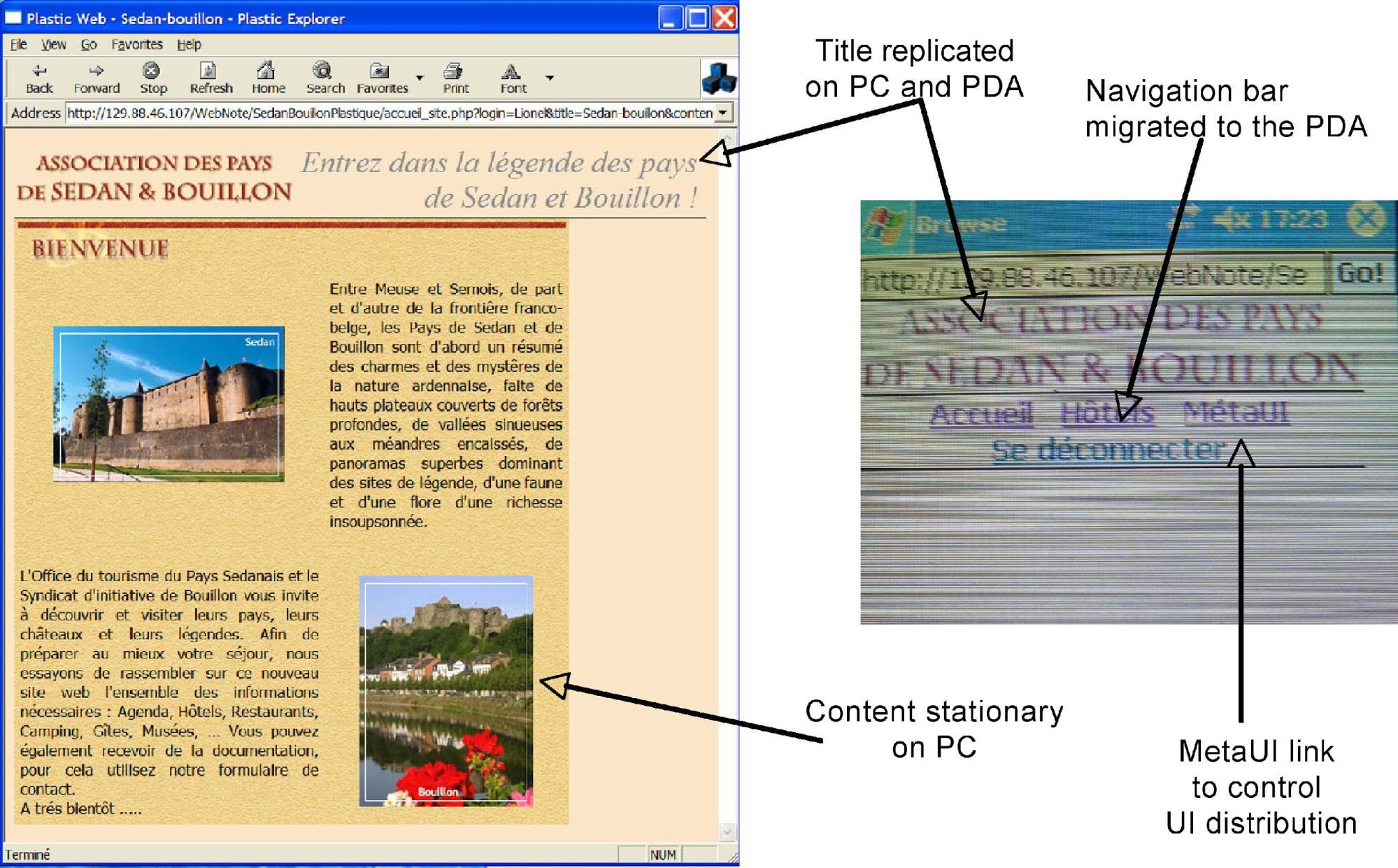
Figure UC8.2. The TWS web site when distributed
across the resources of the ambient interactive space. The MetaUI
link allows users to return to the configuration panel shown on
the right of Figure UC8.1.
8.2 Diagram and Discussion
As shown in Figure UC8.3 for the TWS example, the Final UI is
abstracted away at run time up to the AUI level. In turn, this
AUI serves as input for retargeting and redistribution using a
combination of the user’s request produced by the way of the
meta-UI and of the platform model maintained in the context of
use. The diagram shows the transformation process going from the
PC centralized version to the distributed version. The reverse
process holds when moving from distributed to centralized
use.
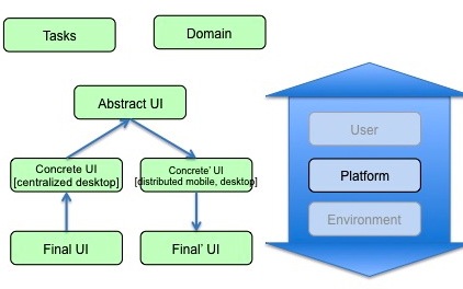
Figure UC8.3. Models used in the TWS use case,
and the process.
Common Generic Requirements
This section presents a list of non-functional requirements
that must drive the process of producing various models defined
at different abstraction levels found in the CRF and that are
applicable to any meta-modelling approach. They were identified
based on the aforementioned use cases. These requirements are not
assumed to be exhaustive, but rather are intended to be
constructive in order to ensure the quality of meta-models and
models produced according to these meta-models. Each respective
meta-model may refine any generic requirement into a specific
requirement that precises how to address each requirement in each
specific case.
Refers to the ability of a (meta-)model to abstract all real
world aspects of interest via appropriate concepts, attributes,
and relationships. In theory, completeness is aimed at producing
a (meta-)model that covers all real world aspects of interest. In
practice however, it may turn out that not all aspects of
interested could be captured in a (meta-)model. For this reason,
completeness is sometimes reduced to expressiveness, which refers
to the ability of a (meta-)model models to abstract a significant
subset of real world aspects of interest that is considered
enough for the purpose of its usage. A sub-property of
completeness, respectively expressiveness, is the graphical
completeness, respectively graphical expressiveness. Both refer
to the ability of a (meta-)model to represent abstractions
relevant for this (meta-)model through appropriate graphical
representations of the concepts, attributes, and relationships.
Note that it is not necessary that all the concepts, attributes,
and relationships of a (meta-)model should be represented
graphically. Therefore, graphical completeness is often
substituted by graphical expressiveness.
Consistency is often decomposed into two sub-properties:
external consistency and internal consistency. External
consistency refers to the ability of a (meta-)model to produce
abstractions of the real world that reproduce the behaviours of
the real world aspects of interest in the same way and that
preserves this behaviour throughout any manipulation of the
(meta-)model. Internal consistency refers to the ability of two
or more (meta-)models to produce abstractions according to the
same methodological approach. This includes: define a common
vocabulary (e.g., the glossary), use this vocabulary in a
systematic way in every (meta-)modelling activity so as to
produce abstractions in the same way, avoid non-unique names.
Rules for ensuring internal consistency could be defined in this
way.
- GR3: Separation of Concerns.
Refers to the ability of a (meta-)model to abstract any real
world aspect of interest into one single abstraction belonging to
one single (meta-)model with as little overlapping as possible
with other abstractions belonging to other (meta-)models.
Refers to the ability of a (meta-)model to extend the
definition of existing abstractions for more specific purposes
without affecting the stability of the overall definition.
Refers to the ability of a (meta-)model to produce
abstractions of real-world aspects of interest in a way that is
as compact as possible with respect to the real-world. A related
principle to concision is the Don’t repeat yourself (DRY)
principle, which refers to the ability of a (meta-)model to
produce abstractions of real-world aspects of interest in a
single, unambiguous, and authoritative representation.
Refers to the ability of one or more (meta-)models to
establish relationships between themselves in order to represent
a real-world aspect of interest. Therefore, correlability is
often decomposed into internal versus external correlability
depending on the type of relationship involved (intra-model
versus inter-model). There are several ways to establish
relationships within a (meta-)model or across (meta-)models such
as, but not limited to: mapping, transformation, mathematical
relationships.
A number of model-based UI tools are available for download.
Although most of them adhere to the principles of the Cameleon
framework, none of them, so far, implements the MBUID
standard.Table 2 below present these tools in a synthetic manner.
The interested reader can access a detailed description of the
tool from its URL.
Table 2. Examples of tools
Table 2. Examples of tools (continued).
|
Name
|
Functional coverage - Specific features
|
|
ConcurTaskTrees Environment (CTTE)
|
Modelling and analysis of single-user and cooperative
CTT task models. In detail:
- Visualise/Edit task models;
- Interactively simulate task models;
- Automatic check the validity/completeness of task
models;
- Save task models in various formats;
- Support the use of informal descriptions for task
modelling;
- Filter nomadic task models according to
platform;
- Support multiple interactive views of CTT task model
specification;
- Support the generation of CTT task models from
WSDL;
- Support the generation of Maria AUIs from CTT task
models;
- Support the generation of Maria CUIs for various
platforms (e.g., desktop, mobile, vocal,
multimodal,..);
- Support the generation of Maria FUIs for various
implementation languages (e.g. Desktop HTML, Mobile HTML,
X+V Desktop, X+V Mobile,..)
|
|
Model-based lAnguage foR Interactive Applications
Environment
(MARIAE)
|
Modelling and analysis of various types of UI
models.
In detail:
- Visualise/Edit Task/AUI/CUI models;
- Edit and apply model transformations;
- Support Web Service -based development of
interactive applications;
- Support the simulation of CTT task models;
- Support the generation of Maria AUIs from CTT task
models;
- Support the generation of Maria CUIs for various
platforms (desktop, mobile, vocal, multimodal,..);
- Support the generation of Maria FUIs for various
implementation languages (e.g. Desktop HTML, Mobile HTML,
X+V Desktop, X+V Mobile,..)
|
Glossary of Terms
A separate glossary of terms
for the Model-Based User Interface domain has been provided. It
contains informal, commonly agreed definitions of relevant terms
and explanatory resources (examples, links etc.)
References
- Ayatsuka, Y., and Rekimoto, J.: TranSticks: Physically
Manipulatable Virtual Connections. In Proceedings of the SIGCHI
conference on Human factors in computing systems (CHI 2005),
ACM Press, New York, NY, pp. 251-260, 2005.
- Bellotti V., Back M., Edwards K., Grinter R., Henderson A.,
and Lopes C. Making Sense of Sensing Systems: Five Questions
for Designers and Researchers. In Proceedings of the SIGCHI
conference on Human factors in computing systems (CHI 2002),
ACM Press, New York, NY, 2002, pp. 415–422, 2002.
- Bodart, F., Hennebert, A.-M., Leheureux, J.-M., Provot, I.,
Vanderdonckt, J., Model-based user interface design in Trident
with Dynamic Specification Language (DSL), IFIP WG 2.7 Working
conf. (Namur, September 1989).
- Bodart, F., Hennebert, A.-M., Leheureux, J.-M., Provot, I.,
Vanderdonckt, J., A Model-based Approach to Presentation: A
Continuum from Task Analysis to Prototype, Proc. of 1st
Eurographics Workshop on Design, Specification, Verification of
Interactive Systems DSV-IS'94 (Bocca di Magra, 8-10 June 1994),
F. Paternó (ed.), Eurographics Series, Berlin, 1994, pp.
25-39.
- Bodart, F., Hennebert, A.-M., Leheureux, J.-M.,
Vanderdonckt, J., Computer-Aided Window Identification in
TRIDENT, Proc. of 5th IFIP TC 13 Int. Conf. on Human-Computer
Interaction INTERACT’95 (Lillehammer, 27-29 June 1995), K.
Nordbyn, P.H. Helmersen, D.J. Gilmore, S.A. Arnesen (eds.),
Chapman & Hall, Loon, 1995, pp. 331-336.
- Bottoni, P., Borgia, F., Buccarella, D., Capuano, D., De
Marsico, M., Labella, A., Stories and signs in an e-learning
environment for deaf people, International Journal of Universal
Access in the Information Society, 2012,
10.1007/s10209-012-0283-y
- Bouillon, L., Vanderdonckt, J., Retargeting Web Pages to
other Computing Platforms with Vaquita, Proc. of IEEE Working
Conf. on Reverse Engineering WCRE’2002 (Richmond, 28 October-1
November 2002), A. van Deursen, E. Burd (eds.), IEEE Computer
Society Press, Los Alamitos, 2002, pp. 339-348.
- Calvary, G.,
Coutaz, J., Thevenin, D., A Unifying Reference Framework
for the Development of Plastic User Interfaces. Proc. of
EHCI 2001, pp. 173-192.
- Calvary, G., Coutaz, J., Thevenin, D., Limbourg, Q.,
Souchon, N., Bouillon, L., Florins, M., Vanderdonckt, J.,
Plasticity of User Interfaces: A Revised Reference Framework,
Proc. of 1st Int. Workshop on Task Models and Diagrams for user
interface design Tamodia’2002 (Bucharest, 18-19 July 2002),
Academy of Economic Studies of Bucharest, INFOREC Printing
House, Bucharest, 2002, pp. 127-134.
- Calvary, G. et al.: The CAMELEON Reference Framework,
CAMELEON Project, September 2002, available at
http://giove.isti.cnr.it/projects/cameleon/pdf/CAMELEON%20D1.1RefFramework.pdf,
2002.
- Calvary, G., Coutaz, J., Thevenin, D., Limbourg, Q.,
Bouillon, L., Vanderdonckt, J., A Unifying Reference Framework
for Multi-Target User Interfaces, Interacting with Computers,
Vol. 15, No. 3, June 2003, pp. 289-308.
- Cantera, J.M., W3C MBUI Incubator Group Report, 2010, see
http://www.w3.org/2005/Incubator/model-based-ui/XGR-mbui-20100504/
- Coleman, R., Lebbon, C., Clarkson, J., & Keates, S.
(2003). From Margins to Mainstream, in: Inclusive Design,
Design for the Whole Population, J. Clarkson et al., eds,
Springer-Verlag, pp. 1–25.
- Coutaz, J., and Calvary, G. HCI and Software Engineering
for User Interface Plasticity. In Human Computer Handbook:
Fundamentals, Evolving technologies, and Emerging Applications,
3rd edition, Julie Jacko Ed., Taylor and Francis Group Ltd
Publ., May 2012.
- Coutaz, J.: Meta User Interface for ambient spaces. In
Proc. TAMODIA 2006, 5th international workshop on Task Models
and Diagrams for User Interface Design, TAMODIA 2006, Coninx,
Luyte, Schneider Eds., Springer-Verlag Berlin, pp. 1-15,
2006.
- Coyette, A., Kieffer, S., Vanderdonckt, J., Multi-Fidelity
Prototyping of User Interfaces, Proc. of 11th IFIP TC 13 Int.
Conf. on Human-Computer Interaction Interact’2007 (Rio de
Janeiro, September 10-14, 2007), Lecture Notes in Computer
Science, Vol. 4662, Springer-Verlag, Berlin, 2007, pp. 149-162.
Brian Shackel Award 2007 for “Outstanding Contribution with
international impact in the field of HCI”.
- Da Silva, P. P.: User Interface Declarative Models and
Development Environments: A Survey. Proc. of the 7th
International Conference on Design, Specification, and
Verification of Interactive Systems, pp. 207-226, 2000.
- Eisenstein, J. and Puerta, A.R. (2000) Adaptation in
automated user-interface design. Proceedings of ACM Int. Conf.
on Intelligent User Interfaces
IUI, ACM Press, New York, pp. 74-81.
- Eriks-Hoogland, I.E, de Groot, S., Post, M.W., & van
der Woude, L.H. (2009). Passive shoulder range of motion
impairment in spinal cord injury during and one year after
rehabilitation. J Rehabil Med., May 2009, 41(6):438-44.
- Fernandez A., Abrahão S., and Insfran E., Empirical
validation of a usability inspection method for model-driven
Web development. Journal of Systems and Software. Volume 86
Issue 1 January 2013 Pages 161-186 (2012).
- Sebastian Feuerstack and Ednaldo Pizzolato; Engineering
Device-spanning, Multimodal Web Applications using a
Model-based Design Approach, WebMedia 2012, the 18th Brazilian
Symposium on Multimedia and the Web, October 15-18, 2012, São
Paulo/SP, Brazil. (Feuerstack2012a)
- Sebastian Feuerstack; MINT-Composer – A Toolchain for the
Model-based Specification of Post-WIMP Interactors, accepted
for XI Workshop on Tools and Applications, WebMedia 2012, the
18th Brazilian Symposium on Multimedia and the Web, October
15-18, 2012, São Paulo/SP, Brazil. (Feuerstack2012b)
- García Frey, A., Ceret, E., Dupuy-Chessa, S., Calvary, G.,
Gabillon, Y. UsiCOMP: an Extensible Model-Driven Composer, In
Proceedings of the 4th ACM SIGCHI Symposium on Engineering
Interactive Computing Systems (EICS 2012). 2012.
- Garcia Frey, A., Calvary, G., Dupuy-Chessa, S., Mandran, N.
Model-Based Self-Explanatory UIs for free, but are they
valuable?, 14th IFIP TC13 Conference on Human-Computer
Interaction (Interact’13), Lecture Notes in Computer Science
(LNCS), Springer, September 2-6, 2013, Cape Town, South
Africa
- Garlan, D., Siewiorek, D., Smailagic, A. and Steenkiste, P.
Project Aura: Towards Distraction-Free Pervasive Computing.
IEEE Pervasive Computing. Volume 21, Number 2, April-June, pp.
22-31, 2002.
- Ghiani, G., Paternò, F., Santoro, C. (2011) User Interface
Migration based on the use of logical descriptions. Migratory
Interactive applications for ubiquitous environments, pp.
45-59.
- Grolaux, D., Van Roy, P., Vanderdonckt, J., QTk: A Mixed
Model-Based Approach to Designing Executable User Interfaces,
Proc. of 8th IFIP Working Conf. on Engineering for
Human-Computer Interaction EHCI'01 (Toronto, 11-13 May 2001),
Lecture Notes in Computer Science, Vol. 2254, Springer-Verlag,
Berlin, 2001, pp. 109-110
- Grolaux, D., Van Roy, P., Vanderdonckt, J., Migratable User
Interfaces: Beyond Migratory User Interfaces, Proc. of 1st
IEEE-ACM Annual International Conference on Mobile and
Ubiquitous Systems: Networking and Services Mobiquitous’04
(Boston, August 22-25, 2004), IEEE Computer Society Press, Los
Alamitos, 2004, pp. 422-430.
- Grolaux, D., Vanderdonckt, J., Van Roy, P., Attach me,
Detach me, Assemble me like You Work, Proc. of 10th IFIP TC 13
Int. Conf. on Human-Computer Interaction Interact’2005 (Rome,
12-16 September 2005), Lecture Notes in Computer Science, Vol.
3585, Springer-Verlag, Berlin, 2005, pp. 198-212.
- Grolaux, D. (2007) Transparent Migration and Adaptation in
a Graphical User Interface Toolkit, PhD thesis, Université
catholique de Louvain, Louvain-la-Neuve, 2007. Available at:
http://citeseerx.ist.psu.edu/viewdoc/download?doi=10.1.1.139.6201&rep=rep1&type=pdf
- Hutchinson, J., Whittle, J., Rouncefield, M., and
Kristoffersen, S. (2011) Empirical assessment of MDE in
industry, Proceedings of the 33rd International Conference on
Software Engineering ICSE'2011, ACM Press, New York, pp.
471-480.
- IBM (2001) Autonomic Computing: IBM’s Perspective on the
State of Information Technology. See also The Vision of Autonomic Computing, Jeffrey O. Kephart,
David M. Chess, IBM Thomas J. Watson Research Center.
- Integranova, 2012.
(Intranova Model Execution System)
- Izadi, S., Brignull, H., Rodden, T., Rogers, Y., and
Underwood, M. 2003. Dynamo: a public interactive surface
supporting the cooperative sharing and exchange of media.
Proceedings of User Interface Software and Technology
UIST’2003) (Vancouver, Canada), ACM Press, New York, pp.
159-168.
- Johanson B., Fox A., and Winograd T.: The Interactive
Workspace Project: Experiences with Ubiquitous Computing Rooms.
IEEE Pervasive Computing Magazine 1(2), April-June 2002.
- Kaklanis, N., Moschonas, P., Moustakas, K., and Tzovaras.
D. (2010) Enforcing accessible design of products and services
through simulated accessibility evaluation", International
Conference on ICT for ageing and eInclusion, CONFIDENCE 2010,
Jyvaskyla, Finland.
- M.Manca, F.Paternò, C.Santoro, L.D.Spano, Generation of
Multi-Device Adaptive MultiModal Web Applications, Proceedings
MobiWIS 2013, LNCS N.8093, pp.218-232, Springer Verlag, August
2013
- Masson, D., Demeure, A., Calvary, G. Magellan, an
evolutionary system to foster user interface design creativity.
In Proceedings of the 2nd ACM SIGCHI symposium on Engineering
interactive computing systems (EICS '10). ACM, New York, NY,
USA, 87-92.
- Meixner, G., Paternó, F., and Vanderdonckt, J.: Past,
Present, and Future of Model-Based User Interface Development.
i-com, 10, 3 (2011), 2-11.
- Mitrovic, N.,
Royo, J.A., and
Mena, E. (2007) Performance Analysis of an Adaptive User
Interface System Based on Mobile Agents, Proc. of
EHCI/DS-VIS 2007, pp. 1-17.
- Models@run-time (2009). Special issue on models at
run-time. IEEE Computer Special Issues, Vol. 42, No. 10.
Available at:
http://www.computer.org/csdl/mags/co/2009/10/index.html
- Mori, G., Paternò, F., Spano, L.D. (2008) Exploiting Web
Services and Model-Based User Interfaces for Multi-device
access to Home applications. DSV-IS 2008, pp. 181-193.
- Myers, B.; Rosson, M. B.: Survey on User Interface
Programming. Proc. of the 10th Annual CHI Conference on Human
Factors in Computing Systems, pp. 195-202, 2000.
- Peña-Guevara, J.C., Berumen-Nafarrete, E., Aguirre-Madrid,
A., Vallejo-Ponce, J., De la Riva-Muñoz, I., &
Núñez-Valdez, J.A. (2005). Anatomically-designed shoulder
hemiarthroplasty made after 3-D models and implanted in a child
with rheumatoid arthritis. A case report. Acta Ortopédica
Mexicana, vol. 19, May-June 2005.
- Pilemalm, S., Hallberg, N., Sparf, M., and Niclason, T.
(Dec. 2012) Practical experiences of model-based development:
Case studies from the Swedish Armed Forces, Systems Engineering
, Volume 15 Issue 4, pp. 407-421.
- Streitz N., Tandler P., Müller-Tomfelde C., and Konomi S.
Roomware: Towards the Next Generation of Human-Computer
Interaction based on an Integrated Design of Real and Virtual
Worlds. In Human-Computer Interaction in the New Millenium,
Carroll J. (Ed.), Addison-Wesley, pp. 553-578, 2001.
- Rodden, T., Crabtree, A., Hemmings, T., Koleva, B., Humble,
J., Akesson, K.P., and Hansson, P. Configuring the Ubiquitous
Home. In Proceedings of the 2004 ACM Symposium on Designing
Interactive Systems (DIS 04) (Cambridge, Massachusetts), ACM
Press, 2004.
- Seffah, A., & Javahery, H. Multiple user Interfaces:
Cross-Platform Applications and Context- Aware Interfaces. In
A. Seffah & H. Javahery (Eds.), Multiple User Interfaces:
Engineering and Application Framework (pp. 11-26). Chichester
(GB): Wiley and Sons, 2004.
- Seissler, M. Modellbasierte Entwicklung kontextsensitiver
Benutzungsschnittstellen zur Unterstützung der mobilen
Instandhaltung, PhD-thesis, Fortschritt-Berichte pak, Band 24,
University of Kaiserslautern, 2013.
- Steenbekkers, L. P. A., & van Beijsterveldt, C. E. M.
(Eds.) (1998). Design-relevant characteristics of ageing users.
Delft, the Netherlands: Delft University Press.
- Szekely, P.: Retrospective and Challenges for Model-Based
Interface Development. Proc. of the 3rd International
Eurographics Workshop, pp. 1-27, 1996.
- Thevenin, D., and Coutaz, J.: Plasticity of User
Interfaces: Framework and Research Agenda. In Proc. Interact99,
Edinburgh, A. Sasse & C. Johnson Eds, IFIP IOS Press Publ.
, pp.110-117, 1999.
- Vanderdonckt, J., Prise en compte des facteurs ergonomiques
dans la conception des interfaces homme-machine, Actes des
journées de travail de Beaune '91 (Beaune, 5-7 March 1991), M.
Adiba, F. Bodart, M. Léonard, Y. Pigneur (eds.), Les Éditions
Systèmes et Information, Genève, 1991.
- Vanderdonckt, J.; Bodart, F.: Encapsulating Knowledge for
Intelligent Automatic Interaction Objects Selection. Proc. of
the ACM Conf. on Human Factors in Computing Systems. ACM Press,
New York, pp. 424-429, 1993.
- WHO, World Heath Organisation: The world is fast ageing –
have we noticed? http://www.who.int/ageing/en/, 2007.
- Zackowski, K.M., Dromerick, A.W., Sahrmann, S.A., Thach,
W.T., & Bastian, A.J. (2004). How do strength, sensation,
spasticity and joint individuation relate to the reaching
deficits of people with chronic hemiparesis?. Brain (2004),
127, 1035-1046.
- Petrasch, R.: Model based user interface design: model
driven architecture und HCI patterns. GI
Softwaretechnik-Trends, Mitt Ges Inform 27(3):5–10.
- Pilemalm, S, Hallberg, N, Sparf, M and Niclasson, T. (2012)
Practical Experiences of Model-based Development: Case studies
from the Swedish Armed Forces, to appear in Journal of Systems
Engineering, Vol. 15, No. 3.
Acknowledgements
In addition to the editors, the following people contributed
to this specification:
- François Beuvens, LILab,
UCL
- Paolo Bottoni, Dipartimento di Informatica, Sapienza
Università di Roma
- Cristina G. Cachón, Fundacion
CTIC
- Javier R. Escolar, Fundacion
CTIC
- Sebastian Feuerstack, OFFIS
e.V.
- Nikolaos Kaklanis, CENTRE
FOR RESEARCH AND TECHNOLOGY HELLAS
- Ignacio Marín, Fundacion
CTIC
- Vivian Motti, LILab, UCL
- Marius Orfgen, DFKI
- Fabio Paternò, ISTI-CNR
- Jaroslav Pullmann, Fraunhofer
Gesellschaft
- Lucio Davide Spano,ISTI-CNR
- Carmen Santoro,ISTI-CNR
- Jean Vanderdonckt, LILab,
UCL