A path represents the outline of a shape which can be filled or
stroked. A path can also be used as a clipping path, to describe
animation, or position text. A path can be used for more than one of
these functions at the same time. (See
Filling, Stroking and Paint Servers,
Clipping and Masking,
Animation ('animateMotion'),
and Text on a Path.)
A path is described using the concept of a current point. In
an analogy with drawing on paper, the current point can be
thought of as the location of the pen. The position of the pen
can be changed, and the outline of a shape (open or closed) can
be traced by dragging the pen in either straight lines or
curves.
Paths represent the geometry of the outline of an object,
defined in terms of moveto (set a new current point),
lineto (draw a straight line), curveto (draw
a curve using a cubic Bézier), arc (elliptical
or circular arc) and closepath (close the current
shape by connecting to the last moveto) commands.
Compound paths (i.e., a path with multiple subpaths) are
possible to allow effects such as "donut holes" in objects.
This chapter describes the syntax, behavior and DOM
interfaces for SVG paths. Various implementation notes for SVG
paths can be found in ‘path’ element implementation
Notes.
A path is defined in SVG using the ‘path’ element.
The basic shapes are all described in terms of what their
equivalent path is, which is
what their shape is as a path. (The equivalent path of a
‘path’ element is simply the path itself.)
In order to define the basic shapes as equivalent paths,
a segment-completing close path operation is defined,
which cannot currently be represented in the basic path syntax.
The outline of a shape for a ‘path’ element is specified using the d
property. See Path data below.
9.3. Path data
9.3.1. General information about path data
A path is defined by including a ‘path’
element on which the d property specifies the
path data. The path data contains the
moveto, lineto, curveto (both cubic and
quadratic Béziers), arc and closepath
instructions.
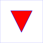
Example triangle01
specifies a path in the shape of a triangle. (The
M indicates a moveto, the
Ls indicate linetos, and the
z indicates a closepath).
<?xml version="1.0" standalone="no"?>
<svg width="4cm" height="4cm" viewBox="0 0 400 400"
     xmlns="http://www.w3.org/2000/svg" version="1.1">
  <title>Example triangle01- simple example of a 'path'</title>
  <desc>A path that draws a triangle</desc>
  <rect x="1" y="1" width="398" height="398"
        fill="none" stroke="blue" />
  <path d="M 100 100 L 300 100 L 200 300 z"
        fill="red" stroke="blue" stroke-width="3" />
</svg>
Path data can contain newline characters and thus can be
broken up into multiple lines to improve readability.
Newlines inside attributes in markup will be normalized to space
characters while parsing.
The syntax of path data is concise in order to allow for
minimal file size and efficient downloads, since many SVG files
will be dominated by their path data. Some of the ways that SVG
attempts to minimize the size of path data are as follows:
All instructions are expressed as one character (e.g., a
moveto is expressed as an M).
Superfluous white space and separators (such as commas) may
be eliminated; for instance, the following contains unnecessary
spaces:
M 100 100 L 200 200
It may be expressed more compactly as:
M100 100L200 200
A command letter may be eliminated if an identical command
letter would otherwise precede it; for instance, the following
contains an unnecessary second "L" command:
M 100 200 L 200 100 L -100 -200
It may be expressed more compactly as:
M 100 200 L 200 100 -100 -200
For most commands there are absolute and relative
versions available (uppercase means absolute coordinates,
lowercase means relative coordinates).
Alternate forms of lineto are available to
optimize the special cases of horizontal and vertical lines
(absolute and relative).
Alternate forms of curve are available to
optimize the special cases where some of the control points
on the current segment can be determined automatically from
the control points on the previous segment.
The path data syntax is a prefix notation (i.e., commands
followed by parameters). The only allowable decimal point is a
Unicode
U+0046 FULL STOP (".") character (also referred to in Unicode as
PERIOD, dot and decimal point) and no other delimiter
characters are allowed [UNICODE].
(For example, the following is an
invalid numeric value in a path data stream: "13,000.56".
Instead, say: "13000.56".)
For the relative versions of the commands, all coordinate
values are relative to the current point at the start of the
command.
In the tables below, the following notation is used to
describe the syntax of a given path command:
(): grouping of parameters
+: 1 or more of the given parameter(s) is required
In the description of the path commands, cpx and
cpy represent the coordinates of the current point.
The d property is used to specify the shape of a ‘path’ element.
The value none indicates that there is no
path data for the element. For ‘path’ elements, this means that the
element does not render or contribute to the bounding box of ancestor
container elements.
A path is made up of multiple segments, and every command, either explicit
or implicit, other than moveto or closepath,
defines one path segment.
All coordinates and lengths specified within path data must be treated as
being in user units in the current user coordinate system.
The <string> value
specifies a shape using a path data string. The contents of the
<string> value must match the svg-pathEBNF grammar defined below, and errors within the string are handled according to
the rules in the Path Data Error Handling section.
If the path data string contains no valid commands, then the behavior
is the same as the none value.
For animation, two d property values can only be
interpolated smoothly when the path data strings contain have the
same structure, (i.e. exactly the same number and types of path data
commands which are in the same order). If an animation is specified
and the lists of path data commands do not have the same structure,
then the values must be
interpolated
using the
discrete
animation type.
If the list of path data commands have the same structure, then each
parameter to each path data command must be
interpolated
separately as
real numbers. Flags and booleans must be interpolated as
fractions between zero and one, with any non-zero value considered
to be a value of one/true.
Resolved that "d will become a presentation attribute (no name
change) with path data string as value" at
London
Editor's Meeting.
The following sections list the commands that canbe used
in path data strings. Those that
draw straight line segments include the lineto commands
(L, l,
H, h, V and v)
and the close path commands
(Z and z). These three groups of commands draw curves:
Cubic
Bézier commands (C,
c, S and
s). A cubic Bézier segment is defined
by a start point, an end point, and two control points.
Quadratic
Bézier commands (Q,
q, T and
t). A quadratic Bézier segment is
defined by a start point, an end point, and one control
point.
The "moveto" commands (M or
m) must establish a new initial point
and a new current point. The effect is as if the "pen" were lifted and moved to
a new location. A path data segment (if there is one) must begin with a "moveto"
command. Subsequent "moveto" commands (i.e., when the "moveto"
is not the first command) represent the start of a new
subpath:
Command
Name
Parameters
Description
M (absolute) m (relative)
moveto
(x y)+
Start a new sub-path at the given (x,y) coordinates.
M (uppercase) indicates that absolute
coordinates will follow; m (lowercase)
indicates that relative coordinates will follow. If a moveto is
followed by multiple pairs of coordinates, the subsequent pairs
are treated as implicit lineto commands. Hence, implicit lineto
commands will be relative if the moveto is relative, and
absolute if the moveto is absolute. If a relative moveto
(m) appears as the first element of the path,
then it is treated as a pair of absolute coordinates. In this
case, subsequent pairs of coordinates are treated as relative
even though the initial moveto is interpreted as an absolute moveto.
When a relative m command is used, the
position moved to is (cpx + x,
cpy + y).
9.3.4. The "closepath" command
The "closepath" (Z or z)
ends the current subpath by connecting it back to its initial point.
An automatic
straight line is drawn from the current point to the initial point
of the current subpath. This path segment may be of zero
length.
If a "closepath" is followed immediately by a "moveto", then the
"moveto" identifies the start point of the next subpath.
If a "closepath" is followed immediately by any other command, then
the next subpath starts at the same initial point as the current
subpath.
When a subpath ends in a "closepath," it differs in behavior
from what happens when "manually" closing a subpath via a
"lineto" command in how ‘stroke-linejoin’
and ‘stroke-linecap’ are implemented. With "closepath", the end of the final segment
of the subpath is "joined" with the start of the initial
segment of the subpath using the current value of ‘stroke-linejoin’.
If you instead "manually" close the subpath via a "lineto"
command, the start of the first segment and the end of the last
segment are not joined but instead are each capped using the
current value of ‘stroke-linecap’.
At the end of the command, the new current point is set to the
initial point of the current subpath.
Command
Name
Parameters
Description
Z or z
closepath
(none)
Close the current subpath by connecting it back to the current
subpath's initial point (see prose above). Since the
Z and z
commands take no parameters, they have an identical effect.
A closed subpath must be closed with a
"closepath" command, this "joins" the first and last path segments.
Any other path is an open subpath.
If a "closepath" is followed immediately by a
"moveto", then the "moveto" identifies the start point of the
next subpath. If a "closepath" is followed immediately by any
other command, then the next subpath must start at the same initial point
as the current subpath.
9.3.4.1. Segment-completing close path operation
In order to represent the basic shapes as equivalent paths,
there must be a way to close curved shapes
without introducing an additional straight-line segment
(even if that segment would have zero length).
For that purpose, a segment-completing close path operation is defined here.
A segment-completing close path operation combines with the previous path command,
with two effects:
It ensures that the final coordinate point of the previous command exactly matches
the initial point of the current subpath.
It joins the final and initial points of the subpath, making it a closed subpath.
Segment-completing close path operations are not currently supported
as a command in the path data syntax.
The working group has proposed such a syntax for future versions of the specification.
9.3.5. The "lineto" commands
The various "lineto" commands draw straight lines from the
current point to a new point:
Command
Name
Parameters
Description
L (absolute) l (relative)
lineto
(x y)+
Draw a line from the current point to the given (x,y)
coordinate which becomes the new current point.
L (uppercase) indicates that absolute
coordinates will follow; l (lowercase)
indicates that relative coordinates will follow. A number
of coordinates pairs may be specified to draw a polyline.
At the end of the command, the new current point is set to
the final set of coordinates provided.
H (absolute) h (relative)
horizontal lineto
x+
Draws a horizontal line from the current point.
H (uppercase) indicates
that absolute coordinates will follow; h
(lowercase) indicates that relative coordinates will
follow. Multiple x values can be provided (although usually
this doesn't make sense). An H or h
command is equivalent to an L or l
command with 0 specified for the y coordinate.
At the end of the command, the new current point is
taken from the final coordinate value.
V (absolute) v (relative)
vertical lineto
y+
Draws a vertical line from the current point.
V (uppercase) indicates that
absolute coordinates will follow; v
(lowercase) indicates that relative coordinates will
follow. Multiple y values can be provided (although usually
this doesn't make sense). A V or v
command is equivalent to an L or l
command with 0 specified for the x coordinate.
At the end of the command, the new current point is
taken from the final coordinate value.
When a relative l command is used, the
end point of the line is (cpx + x,
cpy + y).
When a relative h command is used,
the end point of the line is (cpx + x,
cpy). This means
that an h command with a positive x
value draws a horizontal line in the direction of the positive x-axis.
When a relative v command is used,
the end point of the line is (cpx,
cpy + y).
9.3.6. The cubic Bézier curve commands
The cubic Bézier commands are as follows:
Command
Name
Parameters
Description
C (absolute) c (relative)
curveto
(x1 y1 x2 y2 x y)+
Draws a cubic Bézier curve from the current
point to (x,y) using (x1,y1) as the control point at the
beginning of the curve and (x2,y2) as the control point at
the end of the curve. C (uppercase)
indicates that absolute coordinates will follow;
c (lowercase) indicates that relative
coordinates will follow. Multiple sets of coordinates may
be specified to draw a polybézier. At the end of the
command, the new current point becomes the final (x,y)
coordinate pair used in the polybézier.
S (absolute) s (relative)
shorthand/smooth curveto
(x2 y2 x y)+
Draws a cubic Bézier curve from the current
point to (x,y). The first control point is assumed to be
the reflection of the second control point on the previous
command relative to the current point. (If there is no
previous command or if the previous command was not an C,
c, S or s, assume the first control point is coincident
with the current point.) (x2,y2) is the second control
point (i.e., the control point at the end of the curve).
S (uppercase) indicates that absolute
coordinates will follow; s (lowercase)
indicates that relative coordinates will follow. Multiple
sets of coordinates may be specified to draw a
polybézier. At the end of the command, the new
current point becomes the final (x,y) coordinate pair used
in the polybézier.
When a relative c or s
command is used, each of the relative coordinate pairs
is computed as for those in an m command.
For example, the final control point of the curve of
both commands is (cpx + x,
cpy + y).
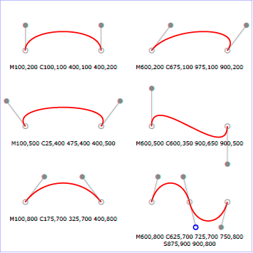
Example cubic01 shows some
simple uses of cubic Bézier commands within a path. The
example uses an internal CSS style sheet to assign styling
properties. Note that the control point for the "S" command is
computed automatically as the reflection of the control point
for the previous "C" command relative to the start point of the
"S" command.
The following picture shows some how cubic Bézier
curves change their shape depending on the position of the
control points. The first five examples illustrate a single
cubic Bézier path segment. The example at the lower
right shows a "C" command followed by an "S" command.
Draws a quadratic Bézier curve from the current
point to (x,y) using (x1,y1) as the control point.
Q (uppercase) indicates that absolute
coordinates will follow; q (lowercase)
indicates that relative coordinates will follow. Multiple
sets of coordinates may be specified to draw a
polybézier. At the end of the command, the new
current point becomes the final (x,y) coordinate pair used
in the polybézier.
T (absolute) t (relative)
Shorthand/smooth quadratic Bézier curveto
(x y)+
Draws a quadratic Bézier curve from the current
point to (x,y). The control point is assumed to be the
reflection of the control point on the previous command
relative to the current point. (If there is no previous
command or if the previous command was not a Q, q, T or t,
assume the control point is coincident with the current
point.) T (uppercase) indicates that
absolute coordinates will follow; t
(lowercase) indicates that relative coordinates will
follow. At the end of the command, the new current point
becomes the final (x,y) coordinate pair used in the
polybézier.
When a relative q or t
command is used, each of the relative coordinate pairs
is computed as for those in an m command.
For example, the final control point of the curve of
both commands is (cpx + x,
cpy + y).
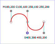
Example quad01 shows some
simple uses of quadratic Bézier commands within a path.
Note that the control point for the "T" command is computed
automatically as the reflection of the control point for the
previous "Q" command relative to the start point of the "T"
command.
<?xml version="1.0" standalone="no"?>
<svg width="12cm" height="6cm" viewBox="0 0 1200 600"
     xmlns="http://www.w3.org/2000/svg" version="1.1">
  <title>Example quad01 - quadratic Bézier commands in path data</title>
  <desc>Picture showing a "Q" a "T" command,
        along with annotations showing the control points
        and end points</desc>
  <rect x="1" y="1" width="1198" height="598"
        fill="none" stroke="blue" stroke-width="1" />

  <path d="M200,300 Q400,50 600,300 T1000,300"
        fill="none" stroke="red" stroke-width="5"  />
  <!-- End points -->
  <g fill="black" >
    <circle cx="200" cy="300" r="10"/>
    <circle cx="600" cy="300" r="10"/>
    <circle cx="1000" cy="300" r="10"/>
  </g>
  <!-- Control points and lines from end points to control points -->
  <g fill="#888888" >
    <circle cx="400" cy="50" r="10"/>
    <circle cx="800" cy="550" r="10"/>
  </g>
  <path d="M200,300 L400,50 L600,300
           L800,550 L1000,300"
        fill="none" stroke="#888888" stroke-width="2" />
</svg>
(rx ry x-axis-rotation large-arc-flag sweep-flag x
y)+
Draws an elliptical arc from the current point to
(x, y). The size and
orientation of the ellipse are defined by two radii
(rx, ry) and an
x-axis-rotation, which indicates how the
ellipse as a whole is rotated, in degrees, relative to the current
coordinate system. The center (cx,
cy) of the ellipse is calculated
automatically to satisfy the constraints imposed by the
other parameters. large-arc-flag and
sweep-flag contribute to the automatic
calculations and help determine how the arc is drawn.
When a relative a command is used, the end point
of the arc is (cpx + x,
cpy + y).
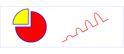
Example arcs01 shows some
simple uses of arc commands within a path.
<?xml version="1.0" standalone="no"?>
<svg width="12cm" height="5.25cm" viewBox="0 0 1200 400"
     xmlns="http://www.w3.org/2000/svg" version="1.1">
  <title>Example arcs01 - arc commands in path data</title>
  <desc>Picture of a pie chart with two pie wedges and
        a picture of a line with arc blips</desc>
  <rect x="1" y="1" width="1198" height="398"
        fill="none" stroke="blue" stroke-width="1" />

  <path d="M300,200 h-150 a150,150 0 1,0 150,-150 z"
        fill="red" stroke="blue" stroke-width="5" />
  <path d="M275,175 v-150 a150,150 0 0,0 -150,150 z"
        fill="yellow" stroke="blue" stroke-width="5" />

  <path d="M600,350 l 50,-25
           a25,25 -30 0,1 50,-25 l 50,-25
           a25,50 -30 0,1 50,-25 l 50,-25
           a25,75 -30 0,1 50,-25 l 50,-25
           a25,100 -30 0,1 50,-25 l 50,-25"
        fill="none" stroke="red" stroke-width="5"  />
</svg>
The elliptical arc command draws a section of an ellipse
which must meet the following constraints:
the arc starts at the current point
the arc ends at point (x,
y)
the ellipse has the two radii (rx,
ry)
the x-axis of the ellipse is rotated by
x-axis-rotation degrees relative to the x-axis of
the current coordinate system.
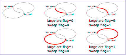
For most situations, there are actually four different arcs
(two different ellipses, each with two different arc sweeps)
that satisfy these constraints. large-arc-flag
and sweep-flag indicate which one of the four
arcs are drawn, as follows:
Of the four candidate arc sweeps, two will represent an
arc sweep of greater than or equal to 180 degrees (the
"large-arc"), and two will represent an arc sweep of less
than or equal to 180 degrees (the "small-arc"). If
large-arc-flag is '1', then one of the two
larger arc sweeps will be chosen; otherwise, if
large-arc-flag is '0', one of the smaller
arc sweeps will be chosen,
If sweep-flag is '1', then the arc will
be drawn in a "positive-angle" direction (i.e., the ellipse
formula x=cx+rx*cos(theta)
and y=cy+ry*sin(theta) is
evaluated such that theta starts at an angle corresponding to
the current point and increases positively until the arc
reaches (x,y)). A value of 0 causes the arc to be drawn in a
"negative-angle" direction (i.e., theta starts at an angle
value corresponding to the current point and decreases until
the arc reaches (x,y)).
The following illustrates the four combinations of
large-arc-flag and sweep-flag
and the four different arcs that will be drawn based on the
values of these flags. For each case, the following path data
command was used:
The Implementation Notes appendix
has relevant formulae for software that needs to convert
SVG arc notation to a format that uses center points and arc sweeps.
The processing of the EBNF must consume as much of a given
EBNF production as possible, stopping at the point when a
character is encountered which no longer satisfies the
production. Thus, in the string "M 100-200", the first
coordinate for the "moveto" consumes the characters "100" and
stops upon encountering the minus sign because the minus sign
cannot follow a digit in the production of a "coordinate". The
result is that the first coordinate will be "100" and the
second coordinate will be "-200".
Similarly, for the string "M 0.6.5", the first coordinate of
the "moveto" consumes the characters "0.6" and stops upon
encountering the second decimal point because the production of
a "coordinate" only allows one decimal point. The result is
that the first coordinate will be "0.6" and the second
coordinate will be ".5".
Note that the EBNF allows the path data string in the
d property to be empty. This is not
an error, instead it disables rendering of the path.
Rendering is also disabled when the d property
has the value none.
If path data not matching the grammar is encountered, then the path data is in error
(see Error Handling).
9.4. Path directionality
Some features, such as the orientation
of markers and the shapes of
line caps, are defined in terms of
the direction of the path at a given distance along the path or at the
start or end of an individual segment.
The direction of a path at a specified
distance along the path is defined as follows:
This will "move past"
zero length segments, and choose the later segment if the distance
is at the boundary between two non-zero length segments.
The default direction at segment boundaries is overriden
when calculating a cap shape and when rendering markers.
Otherwise, the given distance along the path occurs in the middle
of a non-zero length path segment. The direction is simply the direction
of the curve at that point. If the point lies at a discontinuity, such as
a cusp in a Bézier segment, then the direction is undefined; in this case,
a direction between the incoming and outgoing direction around the discontinuity
should be used.
The direction at the start
of a path segment is defined as follows:
If length of the entire path the segment belongs to is zero, then the
direction at the start of the segment points in the same direction as the
positive x-axis.
Otherwise, if the path segment is zero length and the segment does not
have any preceding non-zero length segments, then the direction at the
start of the segment is the same as the
direction at the end of the segment.
Otherwise, the path segment is non-zero length. The direction at the
start of the segment is simply the direction coming out of the segment's start
point.
The direction at the end of a path
segment is defined as follows:
If length of the entire path the segment belongs to is zero, then the
direction at the end of the segment points in the same direction as the
positive x-axis.
Otherwise, if the path segment is zero length and the segment does not
have any following non-zero length segments, then the direction at the
end of the segment is the same as the
direction at the start of the segment.
Otherwise, the path segment is non-zero length. The direction at the
end of the segment is simply the direction coming in to the segment's end
point.
9.5. Implementation notes
A conforming SVG user agent must implement features that use path data
according to the following details:
9.5.1. Out-of-range elliptical arc parameters
Arbitrary numerical values are permitted for all elliptical arc parameters
(other than the boolean flags),
but user agents must make the following adjustments for invalid values
when rendering curves or calculating their geometry:
If the endpoint (x, y) of the segment
is identical to the current point
(e.g., the endpoint of the previous segment),
then this is equivalent to omitting the elliptical arc segment entirely.
If either rx or ry is 0,
then this arc is treated as a straight line segment
(a "lineto") joining the endpoints.
If either rx or ry
have negative signs, these are dropped;
the absolute value is used instead.
If rx, ry and x-axis-rotation
are such that there is no solution
(basically, the ellipse is not big enough to reach
from the current point to the new endpoint)
then the ellipse is scaled up
uniformly until there is exactly one solution (until the
ellipse is just big enough).
This forgiving yet consistent treatment of out-of-range
values ensures that:
The inevitable approximations arising from computer
arithmetic cannot cause a valid set of values written by one
SVG implementation to be treated as invalid when read by
another SVG implementation. This would otherwise be a
problem for common boundary cases such as a semicircular
arc.
Continuous animations that cause parameters to pass
through invalid values are not a problem. The motion
remains continuous.
9.5.2. Reflected control points
The S/s and T/t commands indicate that the first control point of
the given cubic Bézier segment is calculated by
reflecting the previous path segment's final control point
relative to the current point. The exact math is as
follows.
If the current point is (curx, cury) and the
final control point of the previous path segment is
(oldx2, oldy2), then the reflected point (i.e., (newx1,
newy1), the first control point of the current path segment) is:
Path segments with zero length are not invalid,
and will affect rendering in the following cases:
If markers are specified, then a marker is drawn on
every applicable vertex, even if the given vertex is the
end point of a zero-length path segment and even if
"moveto" commands follow each other.
As mentioned in Stroke Properties,
linecaps must be painted for zero-length subpaths when
stroke-linecap has a value of
round or
square.
9.5.4. Error handling in path data
Unrecognized contents within a path data stream (i.e.,
contents that are not part of the path data grammar) is an
error.
In such a case, the following error-handling rules must be used:
The general rule for error handling in path data is
that the SVG user agent shall render a ‘path’ element up
to (but not including) the path command containing the
first error in the path data specification. This will
provide a visual clue to the user or developer about
where the error might be in the path data specification.
This rule will greatly discourage generation of invalid
SVG path data.
If a path data command contains an incorrect set of
parameters, then the given path data command is rendered
up to and including the last correctly defined path segment,
even if that path segment is a sub-component of
a compound path data command, such as a "lineto" with
several pairs of coordinates. For example, for the path
data string 'M 10,10 L 20,20,30',
there is an odd number of parameters for the "L" command, which requires an even
number of parameters. The user agent is required to draw
the line from (10,10) to (20,20) and then perform error
reporting since 'L 20 20'
is the last correctly defined segment of the path data specification.
Wherever possible, all SVG user agents shall report
all errors to the user.
9.6. Distance along a path
Various operations, including text on a path and motion animation
and various stroke
operations, require that the user agent compute the
distance along the geometry of a graphics element, such as a ‘path’.
Exact mathematics exist for computing distance along a path,
but the formulas are highly complex and require substantial
computation. It is recommended that authoring products and user
agents employ algorithms that produce as precise results as
possible; however, to accommodate implementation differences
and to help distance calculations produce results that
approximate author intent, the ‘pathLength’ attribute can be used
to provide the author's computation of the total length of the
path so that the user agent can scale distance-along-a-path
computations by the ratio of ‘pathLength’ to the user agent's own
computed value for total path length.
A "moveto" operation within a ‘path’ element is defined to have
zero length. Only the various "lineto", "curveto" and "arcto"
commands contribute to path length calculations.
The author's computation of the total length of the
path, in user units. This value is used to calibrate the
user agent's own distance-along-a-path
calculations with that of the author. The user agent will
scale all distance-along-a-path computations by the ratio
of ‘pathLength’ to the user
agent's own computed value for total path length. ‘pathLength’ potentially affects
calculations for text on a path,
motion animation and
various stroke operations.
A value of zero is valid and must be treated as a scaling factor of infinity.
A value of zero scaled infinitely must remain zero, while any non-percentage value greater
than zero must become +Infinity.