'path' elements, 'text' elements and basic shapes can be filled (which means painting the interior of the object) and stroked (which means painting along the outline of the object). Filling and stroking both can be thought of in more general terms as painting operations.
Certain elements (i.e., 'path', 'polyline', 'polygon' and 'line' elements) can also have marker symbols drawn at their vertices.
With SVG, you can paint (i.e., fill or stroke) with:
SVG uses the general notion of a paint server. Paint servers are specified using a URI reference on a 'fill' or 'stroke' property. Gradients, patterns and solid colors are just specific types of paint servers.
Properties 'fill' and 'stroke' take on a value of type <paint>, which is specified as follows:
| <paint>: |
none | currentColor | <color> [icc-color(<name>[,<icccolorvalue>]*)] | <uri> [ none | currentColor | <color> [icc-color(<name>[,<icccolorvalue>]*)]] | inherit |
| Value: | <paint> (See Specifying paint) |
| Initial: | black |
| Applies to: | shapes and text content elements |
| Inherited: | yes |
| Percentages: | N/A |
| Media: | visual |
| Animatable: | yes |
The 'fill' property paints the interior of the given graphical element. The area to be painted consists of any areas inside the outline of the shape. To determine the inside of the shape, all subpaths are considered, and the interior is determined according to the rules associated with the current value of the 'fill-rule' property. The zero-width geometric outline of a shape is included in the area to be painted.
The fill operation fills open subpaths by performing the fill operation as if an additional "closepath" command were added to the path to connect the last point of the subpath with the first point of the subpath. Thus, fill operations apply to both open subpaths within 'path' elements (i.e., subpaths without a closepath command) and 'polyline' elements.
.| Value: | nonzero | evenodd | inherit |
| Initial: | nonzero |
| Applies to: | shapes and text content elements |
| Inherited: | yes |
| Percentages: | N/A |
| Media: | visual |
| Animatable: | yes |
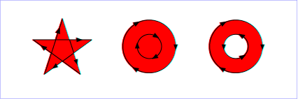
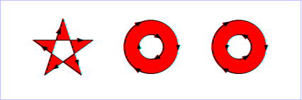
The 'fill-rule' property indicates the algorithm which is to be used to determine what parts of the canvas are included inside the shape. For a simple, non-intersecting path, it is intuitively clear what region lies "inside"; however, for a more complex path, such as a path that intersects itself or where one subpath encloses another, the interpretation of "inside" is not so obvious.
The 'fill-rule' property provides two options for how the inside of a shape is determined:
(Note: the above explanations do not specify what to do if a path segment coincides with or is tangent to the ray. Since any ray will do, one may simply choose a different ray that does not have such problem intersections.)
| Value: | <opacity-value> | inherit |
| Initial: | 1 |
| Applies to: | shapes and text content elements |
| Inherited: | yes |
| Percentages: | N/A |
| Media: | visual |
| Animatable: | yes |
'fill-opacity' specifies the opacity of the painting operation used to paint the interior the current object. (See Painting shapes and text.)
Related properties: 'stroke-opacity' and 'opacity'.
The following are the properties which affect how an element is stroked.
In all cases, all stroking properties which are affected by directionality, such as those having to do with dash patterns, must be rendered such that the stroke operation starts at the same point at which the graphics element starts. In particular, for 'path' elements, the start of the path is the first point of the initial "moveto" command.
For stroking properties such as dash patterns whose computations are dependent on progress along the outline of the graphics element, distance calculations are required to utilize the SVG user agent's standard Distance along a path algorithms.
When stroking is performed using a complex paint server, such as a gradient or a pattern, the stroke operation must be identical to the result that would have occurred if the geometric shape defined by the geometry of the current graphics element and its associated stroking properties were converted to an equivalent 'path' element and then filled using the given paint server.
| Value: | <paint> (See Specifying paint) |
| Initial: | none |
| Applies to: | shapes and text content elements |
| Inherited: | yes |
| Percentages: | N/A |
| Media: | visual |
| Animatable: | yes |
The 'stroke' property paints along the outline of the given graphical element.
A subpath (see Paths) consisting of a single moveto is not stroked. A subpath consisting of a moveto and lineto to the same exact location or a subpath consisting of a moveto and a closepath will be stroked only if the 'stroke-linecap' property is set to "round", producing a circle centered at the given point.
| Value: | <length> | inherit |
| Initial: | 1 |
| Applies to: | shapes and text content elements |
| Inherited: | yes |
| Percentages: | Yes |
| Media: | visual |
| Animatable: | yes |
| Value: | butt | round | square | inherit |
| Initial: | butt |
| Applies to: | shapes and text content elements |
| Inherited: | yes |
| Percentages: | N/A |
| Media: | visual |
| Animatable: | yes |
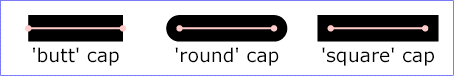
'stroke-linecap' specifies the shape to be used at the end of open subpaths when they are stroked.
View this example as
SVG (SVG- and CSS-enabled browsers only)
| Value: | miter | round | bevel | inherit |
| Initial: | miter |
| Applies to: | shapes and text content elements |
| Inherited: | yes |
| Percentages: | N/A |
| Media: | visual |
| Animatable: | yes |
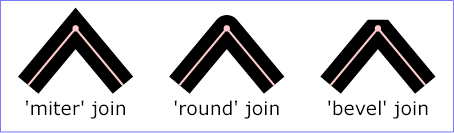
'stroke-linejoin' specifies the shape to be used at the corners of paths or basic shapes when they are stroked.
View this example as
SVG (SVG- and CSS-enabled browsers only)
| Value: | <miterlimit> | inherit |
| Initial: | 4 |
| Applies to: | shapes and text content elements |
| Inherited: | yes |
| Percentages: | N/A |
| Media: | visual |
| Animatable: | yes |
When two line segments meet at a sharp angle and miter joins have been specified for 'stroke-linejoin', it is possible for the miter to extend far beyond the thickness of the line stroking the path. The 'stroke-miterlimit' imposes a limit on the ratio of the miter length to the 'stroke-linewidth'.
| Value: | none | <dasharray> | inherit |
| Initial: | none |
| Applies to: | shapes and text content elements |
| Inherited: | yes |
| Percentages: | yes (see below) |
| Media: | visual |
| Animatable: | yes (non-additive) |
'stroke-dasharray' controls the pattern of dashes and gaps used to stroke paths. <dasharray> contains a list of comma-separated (with optional white space) <length>s that specify the lengths of alternating dashes and gaps. If an odd number of values is provided, then the list of values is repeated to yield an even number of values. Thus, stroke-dasharray: 5,3,2 is equivalent to stroke-dasharray: 5,3,2,5,3,2.
| Value: | <length> | inherit |
| Initial: | 0 |
| Applies to: | shapes and text content elements |
| Inherited: | yes |
| Percentages: | see prose |
| Media: | visual |
| Animatable: | yes |
'stroke-dashoffset' specifies the distance into the dash pattern to start the dash.
| Value: | <opacity-value> | inherit |
| Initial: | 1 |
| Applies to: | shapes and text content elements |
| Inherited: | yes |
| Percentages: | N/A |
| Media: | visual |
| Animatable: | yes |
'stroke-opacity' specifies the opacity of the painting operation used to stroke the current object. (See Painting shapes and text.)
Related properties: 'fill-opacity' and 'opacity'.
SVG uses two properties, 'display' and 'visibility', to control the visibility of graphical elements or (in the case of the 'display' property) container elements.
The differences between the two properties are as follows:
| Value: |
inline | block | list-item | run-in | compact | marker | table | inline-table | table-row-group | table-header-group | table-footer-group | table-row | table-column-group | table-column | table-cell | table-caption | none | inherit |
| Initial: | inline |
| Applies to: | 'svg', 'g', 'switch', 'a', 'foreignObject', graphics elements (including the 'text' element) and text sub-elements (i.e., 'tspan', 'tref', 'altGlyph', 'textPath') |
| Inherited: | no |
| Percentages: | N/A |
| Media: | all |
| Animatable: | yes |
A value of display: none indicates that the given element and its children shall not be rendered directly (i.e., those elements are not present in the rendering tree). Any value other than none or inherit indicates that the given element shall be rendered by the SVG user agent.
The 'display' property only affects the direct rendering of a given element, whereas it does not prevent elements from being referenced by other elements. For example, setting display: none on a 'path' element will prevent that element from getting rendered directly onto the canvas, but the 'path' element can still be referenced by a 'textPath' element; furthermore, its geometry will be used in text-on-a-path processing even if the 'path' has display: none.
The 'display' property affects direct rendering into offscreen canvases also, such as occurs with the implementation model for masks. Thus, setting display: none on a child of a 'mask' will prevent the given child element from being rendered as part of the mask. Similarly, setting display: none on a child of a 'clipPath' element will prevent the given child element from contributing to the clipping path.
Elements with display: none do not take up space in text layout operations, do not receive events, and do not contribute to bounding box and clipping paths calculations.
Except for any additional information provided in this specification, the normative definition is the CSS2 definition of the 'display' property.
| Value: | visible | hidden | collapse | inherit |
| Initial: | visible |
| Applies to: | graphics elements (including the 'text' element) and text sub-elements (i.e., 'tspan', 'tref', 'altGlyph', 'textPath' and 'a') |
| Inherited: | yes |
| Percentages: | N/A |
| Media: | visual |
| Animatable: | yes |
Note that if the 'visibility' property is set to hidden on a 'tspan', 'tref' or 'altGlyph' element, then the text is invisible but still takes up space in text layout calculations.
Depending on the value of property 'pointer-events', graphics elements which have their 'visibility' property set to hidden still might receive events.
Except for any additional information provided in this specification, the normative definition is the CSS2 definition of the 'visibility' property.
A marker is a symbol which is attached to one or more vertices of 'path', 'line', 'polyline' and 'polygon' elements. Typically, markers are used to make arrowheads or polymarkers. Arrowheads can be defined by attaching a marker to the start or end vertices of 'path', 'line' or 'polyline' elements. Polymarkers can be defined by attaching a marker to all vertices of a 'path', 'line', 'polyline' or 'polygon' element.
The graphics for a marker are defined by a 'marker' element. To indicate that a particular 'marker' element should be rendered at the vertices of a particular 'path', 'line', 'polyline' or 'polygon' element, set one or more marker properties ('marker', 'marker-start', 'marker-mid' or 'marker-end') to reference the given 'marker' element.
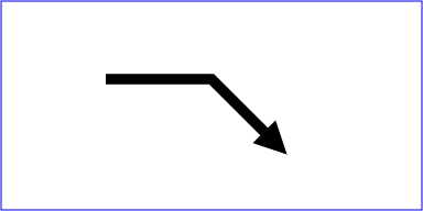
Example Marker draws a triangular marker symbol as an arrowhead at the end of a path.
<?xml version="1.0" standalone="no"?>
<!DOCTYPE svg PUBLIC "-//W3C//DTD SVG 1.1//EN"
  "http://www.w3.org/TR/2002/WD-SVG11-20020215/DTD/svg11.dtd">
<svg width="4in" height="2in"
     viewBox="0 0 4000 2000" version="1.1"
     xmlns="http://www.w3.org/2000/svg">
  <defs>
    <marker id="Triangle"
      viewBox="0 0 10 10" refX="0" refY="5"
      markerUnits="strokeWidth"
      markerWidth="4" markerHeight="3"
      orient="auto">
      <path d="M 0 0 L 10 5 L 0 10 z" />
    </marker>
  </defs>
  <rect x="10" y="10" width="3980" height="1980"
       fill="none" stroke="blue" stroke-width="10" />
  <desc>Placing an arrowhead at the end of a path.
  </desc>
  <path d="M 1000 750 L 2000 750 L 2500 1250"
        fill="none" stroke="black" stroke-width="100"
        marker-end="url(#Triangle)"  />
</svg>
|
View this example as SVG
(SVG-enabled browsers only)
Markers can be animated. The animated effects will show on all current uses of the markers within the document.
The 'marker' element defines the graphics
that is to be used for drawing arrowheads or polymarkers on a
given 'path',
'line',
'polyline' or
'polygon' element.
<!ENTITY % markerExt "" > <!ELEMENT marker (desc|title|metadata|defs| path|text|rect|circle|ellipse|line|polyline|polygon| use|image|svg|g|view|switch|a|altGlyphDef| script|style|symbol|marker|clipPath|mask| linearGradient|radialGradient|pattern|filter|cursor|font| animate|set|animateMotion|animateColor|animateTransform| color-profile|font-face %ceExt;%markerExt;)* > <!ATTLIST marker %stdAttrs; %langSpaceAttrs; externalResourcesRequired %Boolean; #IMPLIED class %ClassList; #IMPLIED style %StyleSheet; #IMPLIED %PresentationAttributes-All; viewBox %ViewBoxSpec; #IMPLIED preserveAspectRatio %PreserveAspectRatioSpec; 'xMidYMid meet' refX %Coordinate; #IMPLIED refY %Coordinate; #IMPLIED markerUnits (strokeWidth | userSpaceOnUse) #IMPLIED markerWidth %Length; #IMPLIED markerHeight %Length; #IMPLIED orient CDATA #IMPLIED > |
Attribute definitions:
Markers are drawn such that their reference point (i.e., attributes refX and refY) is positioned at the given vertex. In other words, a translation transformation is constructed by the user agent to achieve the effect of having point (refX and refY) within the marker content's coordinate system (after any transformations due to the viewBox and preserveAspectRatio attributes) align exactly with the given vertex.
SVG's user agent style sheet sets the 'overflow' property for 'marker' elements to hidden, which causes a rectangular clipping path to be created at the bounds of the marker tile. Unless the 'overflow' property is overridden, any graphics within the marker which goes outside of the marker rectangle will be clipped.
The contents of the 'marker' are relative to a new coordinate system. Attribute markerUnits determines an initial scale factor for transforming the graphics in the marker into the user coordinate system for the referencing element. An additional set of transformations might occur if there is a viewBox attribute, in which case the coordinate system for the contents of the 'marker' will be transformed due to the processing of attributes viewBox and preserveAspectRatio. If there is no viewBox attribute, then the assumed default value for the the viewBox attribute has the origin of the viewBox coincident with the origin of the viewport and the width/height of the viewBox the same as the width/height of the viewport.
Properties inherit into the 'marker' element from its ancestors; properties do not inherit from the element referencing the 'marker' element.
'marker' elements are never rendered directly; their only usage is as something that can be referenced using the 'marker', 'marker-start', 'marker-end' and 'marker-mid' properties. The 'display' property does not apply to the 'marker' element; thus, 'marker' elements are not directly rendered even if the 'display' property is set to a value other than none, and 'marker' elements are available for referencing even when the 'display' property on the 'marker' element or any of its ancestors is set to none.
Event attributes and event listeners attached to the contents of a 'marker' element are not processed; only the rendering aspects of 'marker' elements are processed.
'marker-start' defines the arrowhead or polymarker that shall be drawn at the first vertex of the given 'path' element or basic shape. 'marker-end' defines the arrowhead or polymarker that shall be drawn at the final vertex. 'marker-mid' defines the arrowhead or polymarker that shall be drawn at every other vertex (i.e., every vertex except the first and last). Note that for a 'path' element which ends with a closed sub-path, the last vertex is the same as the initial vertex on the given sub-path. In this case, if 'marker-end' does not equal none, then it is possible that two markers will be rendered on the given vertex. One way to prevent this is to set 'marker-end' to none. (Note that the same comment applies to 'polygon' elements.)
| Value: |
none | inherit | <uri> |
| Initial: | none |
| Applies to: | 'path', 'line', 'polyline' and 'polygon' elements |
| Inherited: | yes |
| Percentages: | N/A |
| Media: | visual |
| Animatable: | yes |
The 'marker' property specifies the marker symbol that shall be used for all points on the sets the value for all vertices on the given 'path' element or basic shape. It is a short-hand for the three individual marker properties:
| Value: | see individual properties |
| Initial: | see individual properties |
| Applies to: | 'path', 'line', 'polyline' and 'polygon' elements |
| Inherited: | yes |
| Percentages: | N/A |
| Media: | visual |
| Animatable: | yes |
Markers are drawn after the given object is filled and stroked.
For each marker that is drawn, a temporary new user coordinate system is established so that the marker will be positioned and sized correctly, as follows:
The rendering effect of a marker is as if the contents of the referenced 'marker' element were deeply cloned into a separate non-exposed DOM tree for each instance of the marker. Because the cloned DOM tree is non-exposed, the SVG DOM does not show the cloned instance of the marker.
For user agents that support Styling with CSS, the conceptual deep cloning of the referenced 'marker' element into a non-exposed DOM tree also copies any property values resulting from the CSS cascade [CSS2-CASCADE] and property inheritance on the referenced element and its contents. CSS2 selectors can be applied to the original (i.e., referenced) elements because they are part of the formal document structure. CSS2 selectors cannot be applied to the (conceptually) cloned DOM tree because its contents are not part of the formal document structure.
For illustrative purposes, we'll repeat the marker example shown earlier:
<?xml version="1.0" standalone="no"?>
<!DOCTYPE svg PUBLIC "-//W3C//DTD SVG 1.1//EN"
  "http://www.w3.org/TR/2002/WD-SVG11-20020215/DTD/svg11.dtd">
<svg width="4in" height="2in"
     viewBox="0 0 4000 2000" version="1.1"
     xmlns="http://www.w3.org/2000/svg">
  <defs>
    <marker id="Triangle"
      viewBox="0 0 10 10" refX="0" refY="5"
      markerUnits="strokeWidth"
      markerWidth="4" markerHeight="3"
      orient="auto">
      <path d="M 0 0 L 10 5 L 0 10 z" />
    </marker>
  </defs>
  <rect x="10" y="10" width="3980" height="1980"
       fill="none" stroke="blue" stroke-width="10" />
  <desc>Placing an arrowhead at the end of a path.
  </desc>
  <path d="M 1000 750 L 2000 750 L 2500 1250"
        fill="none" stroke="black" stroke-width="100"
        marker-end="url(#Triangle)"  />
</svg>
The rendering effect of the above file will be visually identical to the following:
<?xml version="1.0" standalone="no"?>
<!DOCTYPE svg PUBLIC "-//W3C//DTD SVG 1.1//EN"
  "http://www.w3.org/TR/2002/WD-SVG11-20020215/DTD/svg11.dtd">
<svg width="4in" height="2in"
     viewBox="0 0 4000 2000" version="1.1"
     xmlns="http://www.w3.org/2000/svg">

  <desc>File which produces the same effect
      as the marker example file, but without
      using markers.
  </desc>
  <rect x="10" y="10" width="3980" height="1980"
       fill="none" stroke="blue" stroke-width="10" />
  <!-- The path draws as before, but without the marker properties -->
  <path d="M 1000 750 L 2000 750 L 2500 1250"
        fill="none" stroke="black" stroke-width="100"  />

  <!-- The following logic simulates drawing a marker
       at final vertex of the path. -->

  <!-- First off, move the origin of the user coordinate system
       so that the origin is now aligned with the end point of the path. -->
  <g transform="translate(2500,1250)" >

    <!-- Rotate the coordinate system 45 degrees because
         the marker specified orient="auto" and the final segment
         of the path is going in the direction of 45 degrees. -->
    <g transform="rotate(45)" >

      <!-- Scale the coordinate system to match the coordinate system
           indicated by the 'markerUnits' attributes, which in this case has
           a value of 'strokeWidth'. Therefore, scale the coordinate system
           by the current value of the 'stroke-width' property, which is 100. -->
      <g transform="scale(100)" >

        <!-- Translate the coordinate system by
             (-refX*viewBoxToMarkerUnitsScaleX, -refY*viewBoxToMarkerUnitsScaleY)
             in order that (refX,refY) within the marker will align with the vertex.
             In this case, we use the default value for preserveAspectRatio
             ('xMidYMid meet'), which means find a uniform scale factor
             (i.e., viewBoxToMarkerUnitsScaleX=viewBoxToMarkerUnitsScaleY)
             such that the viewBox fits entirely within the viewport ('meet') and
             is center-aligned ('xMidYMid'). In this case, the uniform scale factor
             is markerHeight/viewBoxHeight=3/10=.3. Therefore, translate by
             (-refX*.3,-refY*.3)=(0*.3,-5*.3)=(0,-1.5). -->
        <g transform="translate(0,-1.5)" >

          <!-- There is an implicit clipping path because the user agent style
               sheet says that the 'overflow' property for markers has the value
               'hidden'. To achieve this, create a clipping path at the bounds
               of the viewport. Note that in this case the viewport extends
               0.5 units to the left and right of the viewBox due to
               a uniform scale factor, different ratios for markerWidth/viewBoxWidth
               and markerHeight/viewBoxHeight, and 'xMidYMid' alignment -->
          <clipPath id="cp1" >
            <rect x="-0.5" y="0" width="4" height="3" />
          </clipPath>
          <g clip-path="url(#cp1)" >

            <!-- Scale the coordinate system by the uniform scale factor
                 markerHeight/viewBoxHeight=3/10=.3 to set the coordinate
                 system to viewBox units. -->
            <g transform="scale(.3)" >

              <!-- This 'g' element carries all property values that result from
                   cascading and inheritance of properties on the original 'marker' element.
                   In this example, neither fill nor stroke was specified on the 'marker'
                   element or any ancestors of the 'marker', so the initial values of
                   "black" and "none" are used, respectively. -->
             <g fill="black" stroke="none" >

                <!-- Expand out the contents of the 'marker' element. -->
                <path d="M 0 0 L 10 5 L 0 10 z" />
              </g>
            </g>
          </g>
        </g>
      </g>
    </g>
  </g>
</svg>
View this
example as SVG (SVG-enabled browsers only)
The SVG user agent performs color interpolations and compositing at various points as it processes SVG content. Two properties, 'color-interpolation' and 'color-interpolation-filters', control which color space is used for particular categories of graphics operations. The following table shows which property applies to which graphics operations:
| Graphics operation | Corresponding property |
|---|---|
| interpolating between gradient stops (see Gradient) | 'color-interpolation' |
| interpolating color when performing color animations(see 'animateColor') | 'color-interpolation' |
| alpha compositing of graphics elements into the current background | 'color-interpolation' |
| filter effects | 'color-interpolation-filters' |
Both properties choose between color operations occurring in the sRGB color space or in a (light energy linear) linearized RGB color space.
The conversion formulas between the sRGB color space (i.e., nonlinear with 2.2 gamma curve) and the linearized RGB color space (i.e., color values expressed as sRGB tristimulus values without a gamma curve) can be found in [SRGB]. For illustrative purposes, the following formula shows the conversion from sRGB to linearized RGB:
  R[sRGB] = R[sRGB-8bit] / 255
  G[sRGB] = G[sRGB-8bit] / 255
  B[sRGB] = B[sRGB-8bit] / 255

If R[sRGB], G[sRGB], B[sRGB] <= 0.04045

  R[linearRGB] = R[sRGB] / 12.92
  G[linearRGB] = G[sRGB] / 12.92
  B[linearRGB] = B[sRGB] / 12.92

else if R[sRGB], G[sRGB], B[sRGB] > 0.04045

  R[linearRGB] = ((R[sRGB] + 0.055) / 1.055) ^ 2.4
  G[linearRGB] = ((G[sRGB] + 0.055) / 1.055) ^ 2.4
  B[linearRGB] = ((B[sRGB] + 0.055) / 1.055) ^ 2.4

  R[linearRGB-8bit] = R[linearRGB] * 255
  G[linearRGB-8bit] = G[linearRGB] * 255
  B[linearRGB-8bit] = B[linearRGB] * 255
Out-of-range color values, if supported by the user agent, also are converted using the above formulas. (See Clamping values which are restricted to a particular range.)
| Value: | auto | sRGB | linearRGB | inherit |
| Initial: | sRGB |
| Applies to: | container elements, graphics elements and 'animateColor' |
| Inherited: | yes |
| Percentages: | N/A |
| Media: | visual |
| Animatable: | yes |
The 'color-interpolation' property specifies the color space for gradient interpolations, color animations and alpha compositing.
When a child element is blended into a background, the value of the 'color-interpolation' property on the child determines the type of blending, not the value of the 'color-interpolation' on the parent. For gradients which make use of the xlink:href attribute to reference another gradient, the gradient uses the 'color-interpolation' property value from the gradient element which is directly referenced by the 'fill' or 'stroke' property. When animating colors, color interpolation is performed according to the value of the 'color-interpolation' property on the element being animated.
| Value: | auto | sRGB | linearRGB | inherit |
| Initial: | linearRGB |
| Applies to: | filter primitives |
| Inherited: | yes |
| Percentages: | N/A |
| Media: | visual |
| Animatable: | yes |
The 'color-interpolation-filters' property specifies the color space for imaging operations performed via filter effects.
Note that 'color-interpolation-filters' has a different initial value than 'color-interpolation'. 'color-interpolation-filters' has an initial value of linearRGB, whereas 'color-interpolation' has an initial value of sRGB. Thus, in the default case, filter effects operations occur in the linearRGB color space, whereas all other color interpolations occur by default in the sRGB color space.
The creator of SVG content might want to provide a hint to the implementation about how to make speed vs. quality tradeoffs as it performs color interpolation and compositing. The 'color-rendering' property provides a hint to the SVG user agent about how to optimize its color interpolation and compositing operations.
'color-rendering' takes precedence over 'color-interpolation-filters'. For example, assume 'color-rendering:optimizeSpeed' and 'color-interpolation-filters:linearRGB'. In this case, the SVG user agent should perform color operations in a way that optimizes performance, which might mean sacrificing the color interpolation precision as specified by 'color-interpolation-filters:linearRGB'.
| Value: | auto | optimizeSpeed | optimizeQuality | inherit |
| Initial: | auto |
| Applies to: | container elements, graphics elements and 'animateColor' |
| Inherited: | yes |
| Percentages: | N/A |
| Media: | visual |
| Animatable: | yes |
The creator of SVG content might want to provide a hint to the implementation about what tradeoffs to make as it renders vector graphics elements such as 'path' elements and basic shapes such as circles and rectangles. The 'shape-rendering' property provides these hints.
| Value: |
auto | optimizeSpeed | crispEdges | geometricPrecision | inherit |
| Initial: | auto |
| Applies to: | shapes |
| Inherited: | yes |
| Percentages: | N/A |
| Media: | visual |
| Animatable: | yes |
The creator of SVG content might want to provide a hint to the implementation about what tradeoffs to make as it renders text. The 'text-rendering' property provides these hints.
| Value: |
auto | optimizeSpeed | optimizeLegibility | geometricPrecision | inherit |
| Initial: | auto |
| Applies to: | 'text' elements |
| Inherited: | yes |
| Percentages: | N/A |
| Media: | visual |
| Animatable: | yes |
The creator of SVG content might want to provide a hint to the implementation about how to make speed vs. quality tradeoffs as it performs image processing. The 'image-rendering' property provides a hint to the SVG user agent about how to optimize its image rendering.:
| Value: | auto | optimizeSpeed | optimizeQuality | inherit |
| Initial: | auto |
| Applies to: | images |
| Inherited: | yes |
| Percentages: | N/A |
| Media: | visual |
| Animatable: | yes |
In all cases, resampling must be done in a truecolor (e.g., 24-bit) color space even if the original data and/or the target device is indexed color.
The values of any of the painting properties described in this chapter can be inherited from a given object's parent. Painting, however, is always done on each graphics element individually, never at the container element (e.g., a 'g') level. Thus, for the following SVG, even though the gradient fill is specified on the 'g', the gradient is simply inherited through the 'g' element down into each rectangle, each of which is rendered such that its interior is painted with the gradient.
Example Inheritance
<?xml version="1.0" standalone="no"?>
<!DOCTYPE svg PUBLIC "-//W3C//DTD SVG 1.1//EN"
  "http://www.w3.org/TR/2002/WD-SVG11-20020215/DTD/svg11.dtd">
<svg width="7cm" height="2cm" viewBox="0 0 700 200"
     xmlns="http://www.w3.org/2000/svg" version="1.1">
  <desc>Gradients apply to leaf nodes
  </desc>
  <g>
    <defs>
      <linearGradient id="MyGradient" gradientUnits="objectBoundingBox">
        <stop offset="0%" stop-color="#F60" />
        <stop offset="100%" stop-color="#FF6" />
      </linearGradient>
    </defs>
    <rect x="1" y="1" width="698" height="198"
          fill="none" stroke="blue" stroke-width="2" />
    <g fill="url(#MyGradient)" >
      <rect x="100" y="50" width="200" height="100"/>
      <rect x="400" y="50" width="200" height="100"/>
   </g>
  </g>
</svg>

|
View this example
as SVG (SVG-enabled browsers only)
Any painting properties defined in terms of the object's bounding
box use the bounding box of the graphics element to
which the operation applies. Note that
text elements are defined such that any painting
operations defined in terms of the object's bounding
box use the bounding box of the entire
'text' element. (See the discussion of object
bounding box units and text elements.)
The Full Paint Attribute Module defines the PaintPresentationAttrs attribute set.
| Collection Name | Attributes in Collection |
|---|---|
| PaintPresentationAttrs | fill, fill-opacity, fill-rule, stroke, stroke-dasharray stroke-dashoffset, stroke-linecap, stroke-linejoin, stroke-miterlimit, stroke-opacity, stroke-width |
The Tiny Paint Attribute Module defines the PaintPresentationAttrs attribute set.
| Collection Name | Attributes in Collection |
|---|---|
| PaintPresentationAttrs | fill, fill-rule, stroke, stroke-dasharray stroke-dashoffset, stroke-linecap, stroke-linejoin, stroke-miterlimit, stroke-width |
The Full Opacity Attribute Module defines the OpacityPresentationAttrs attribute set.
| Collection Name | Attributes in Collection |
|---|---|
| OpacityPresentationAttrs | opacity |
The Full Graphics Attribute Module defines the GraphicsPresentationAttrs attribute set.
| Collection Name | Attributes in Collection |
|---|---|
| GraphicsPresentationAttrs | display, image-rendering, pointer-events, shape-rendering, text-rendering, visibility |
The Tiny Graphics Attribute Module defines the GraphicsPresentationAttrs attribute set.
| Collection Name | Attributes in Collection |
|---|---|
| GraphicsPresentationAttrs | display, visibility |
| Elements | Attributes | Content Model |
|---|---|---|
| marker | StdAttrs, ExternalResourcesRequiredAttrs, StyleAttrs, PresentationAttrsAll, viewBox, preserveAspectRatio, refX, refY, markerUnits, markerWidth, markerHeight, orient | (DescriptionElements | StructureElements | GraphicalElements | TextElements | ImageElements | ViewElements | ConditionalElements | HyperlinkingElements | ScriptElements | ClipElements | MaskElements | GradientElements | PatternElements | FilterElements | CursorElements | FontElements | ColorElements | AnimationElements)* |
The following interfaces are defined below: SVGPaint, SVGMarkerElement.
The SVGPaint interface corresponds to basic type <paint> and represents the values of properties 'fill' and 'stroke'.
interface SVGPaint : SVGColor {
  // Paint Types
  const unsigned short SVG_PAINTTYPE_UNKNOWN               = 0;
  const unsigned short SVG_PAINTTYPE_RGBCOLOR              = 1;
  const unsigned short SVG_PAINTTYPE_RGBCOLOR_ICCCOLOR     = 2;
  const unsigned short SVG_PAINTTYPE_NONE                  = 101;
  const unsigned short SVG_PAINTTYPE_CURRENTCOLOR          = 102;
  const unsigned short SVG_PAINTTYPE_URI_NONE              = 103;
  const unsigned short SVG_PAINTTYPE_URI_CURRENTCOLOR      = 104;
  const unsigned short SVG_PAINTTYPE_URI_RGBCOLOR          = 105;
  const unsigned short SVG_PAINTTYPE_URI_RGBCOLOR_ICCCOLOR = 106;
  const unsigned short SVG_PAINTTYPE_URI                   = 107;

  readonly attribute unsigned short paintType;
  readonly attribute DOMString      uri;

  void setUri ( in DOMString uri );
  void setPaint ( in unsigned short paintType, in DOMString uri, in DOMString rgbColor, in DOMString iccColor )
                  raises( SVGException );
};
| SVG_PAINTTYPE_UNKNOWN | The paint type is not one of predefined types. It is invalid to attempt to define a new value of this type or to attempt to switch an existing value to this type. | |
| SVG_PAINTTYPE_RGBCOLOR | An sRGB color has been specified without an alternative ICC color specification. | |
| SVG_PAINTTYPE_RGBCOLOR_ICCCOLOR | An sRGB color has been specified along with an alternative ICC color specification. | |
| SVG_PAINTTYPE_NONE | Corresponds to a 'none' value on a <paint> specification. | |
| SVG_PAINTTYPE_CURRENTCOLOR | Corresponds to a 'currentColor' value on a <paint> specification. | |
| SVG_PAINTTYPE_URI_NONE | A URI has been specified, along with an explicit 'none' as the backup paint method in case the URI is unavailable or invalid. | |
| SVG_PAINTTYPE_URI_CURRENTCOLOR | A URI has been specified, along with 'currentColor' as the backup paint method in case the URI is unavailable or invalid. | |
| SVG_PAINTTYPE_URI_RGBCOLOR | A URI has been specified, along with an sRGB color as the backup paint method in case the URI is unavailable or invalid. | |
| SVG_PAINTTYPE_URI_RGBCOLOR_ICCCOLOR | A URI has been specified, along with both an sRGB color and alternate ICC color as the backup paint method in case the URI is unavailable or invalid. | |
| SVG_PAINTTYPE_URI | Only a URI has been specified. |
| in DOMString uri | The URI for the desired paint server. |
paintType requires a URI, then
uri must be non-null and a valid string;
otherwise, uri must be null. If
paintType requires an RGBColor, then
rgbColor must be a valid RGBColor object;
otherwise, rgbColor must be null. If
paintType requires an SVGICCColor, then
iccColor must be a valid SVGICCColor
object; otherwise, iccColor must be null.
| in unsigned short paintType | One of the defined constants for paintType. | |
| in DOMString uri | The URI for the desired paint server, or null. | |
| in DOMString rgbColor | The specification of an sRGB color, or null. | |
| in DOMString iccColor | The specification of an ICC color, or null. |
| SVGException |
SVG_INVALID_VALUE_ERR: Raised if one of the
parameters has an invalid value.
|
The SVGMarkerElement interface corresponds to the 'marker' element.
interface SVGMarkerElement :
                SVGElement,
                SVGLangSpace,
                SVGExternalResourcesRequired,
                SVGStylable,
                SVGFitToViewBox {

  // Marker Unit Types
  const unsigned short SVG_MARKERUNITS_UNKNOWN        = 0;
  const unsigned short SVG_MARKERUNITS_USERSPACEONUSE = 1;
  const unsigned short SVG_MARKERUNITS_STROKEWIDTH    = 2;
  // Marker Orientation Types
  const unsigned short SVG_MARKER_ORIENT_UNKNOWN      = 0;
  const unsigned short SVG_MARKER_ORIENT_AUTO         = 1;
  const unsigned short SVG_MARKER_ORIENT_ANGLE        = 2;

  readonly attribute SVGAnimatedLength      refX;
  readonly attribute SVGAnimatedLength      refY;
  readonly attribute SVGAnimatedEnumeration markerUnits;
  readonly attribute SVGAnimatedLength      markerWidth;
  readonly attribute SVGAnimatedLength      markerHeight;
  readonly attribute SVGAnimatedEnumeration orientType;
  readonly attribute SVGAnimatedAngle      orientAngle;

  void setOrientToAuto (  );
  void setOrientToAngle ( in SVGAngle angle );
};
| SVG_MARKERUNITS_UNKNOWN | The marker unit type is not one of predefined types. It is invalid to attempt to define a new value of this type or to attempt to switch an existing value to this type. | |
| SVG_MARKERUNITS_USERSPACEONUSE | The value of attribute markerUnits is 'userSpaceOnUse'. | |
| SVG_MARKERUNITS_STROKEWIDTH | The value of attribute markerUnits is 'strokeWidth'. |
| SVG_MARKER_ORIENT_UNKNOWN | The marker orientation is not one of predefined types. It is invalid to attempt to define a new value of this type or to attempt to switch an existing value to this type. | |
| SVG_MARKER_ORIENT_AUTO | Attribute orient has value 'auto'. | |
| SVG_MARKER_ORIENT_ANGLE | Attribute orient has an angle value. |
| in SVGAngle angle | The angle value to use for attribute orient. |