Warning:
This wiki has been archived and is now read-only.
Agriculture Meteorology Sensor Network
Contents
Agriculture Meteorology Sensor Network
Agriculture Meteorology resources (OWL)
- OWL file: phenonet
- OWL file: AWS and WMO AWS Metadata catalogue
- OWL file: CF (properties) and Climate and Forecast Metadata Conventions
- OWL file: CF (features) and CF grammar
- OWL file: QU, documentation and QUDV web site
- OWL file: QU Rec 20 and UN/CEFACT recs
The Agriculture Meteorology ontology (ssn-phenonet)
The Phenonet project led by the High Resolution Plant Phenomics Centre is using CSIRO-developed smart sensor nodes to record microclimate and plant data in the field in an effort to select new plant varieties suited to difficult growing conditions.
The Phenonet sensor network system uses a range of different micro-climate sensors such as automatic weather stations, solar radiation and photosynthetically active radiation sensors, soil moisture and soil temperature sensors, and infrared thermometers to measure leaf temperature.
The example presented here serves two purposes:
- to showcase the addition to the SSN ontology of "sensor type" definitions for the Agriculture Meteorology domain, and the dependency of these definitions on feature and property definitions,
- to serve as the source of definitions for the application software developed for the sensor network and for other applications exploiting the data generated by the sensors.
In field experiments, different kinds of sensors may be combined to serve the scientific objectives of a sensor network deployment. For example, different soil moisture sensors can be used to record the soil moisture at different depths or a master weather station can be used in conjunction with less expensive temperature sensors to record the temperature in several locations.
This example uses an ontology derived from the Automatic Weather Station taxonomy proposed by WMO experts for the specification of AWS Metadata catalogue, some feature and property definitions from the Climate and Forecast Metadata Conventions and a quantity and unit of measurement ontology, extending the SysML QUDV ontology with data sourced from UN/CEFACT recommendation 20.
This example also shows how output variables can be defined as a list of independent processes implemented by each sensor. This specification captures some of the information required to program the software modules run on the sensor nodes and to provide the data to the end user after its capture. More information on this second use case is provided in the Process module documentation.
Sensor selection
Figure 5.38 shows how the SSN ontology can be extended to specify the sensors, properties and features of the Phenonet system so that it is possible to answer questions such as "which sensor can provide data about a particular feature?". On the left side of the figure, the classes with a name starting with aws: belong to the Automatic Weather Station ontology which provides a taxonomy of the different types of sensors which can be used in Agriculture Meteorology. On the middle and right hand side of the figure, the classes and individuals with a name starting with cf: and cf-features: belong to the Climate and Forecast ontologies.
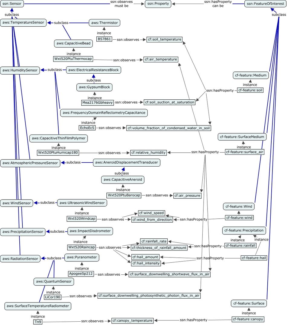
Figure 5.38 - Agriculture meteorology example: sensors and features
System view
Figure 5.39 below shows an example of an Automatic Weather Station based on the Vaisala WXT 520 model.
It shows the weather station as a system and the relation to its subsystems (sensors) which perform the different sensing tasks and collect the following variables: pressure, temperature, humidity, wind speed and direction, and rain intensity and volume. In the model we use, the pressure, temperature, and humidity sensors are combined in a specific sub-system (PTU). This sub-system is not represented here.
The sensor type hierarchy for the different types of sensors included in this Weather Station model is also pictured. And for each instance of a sensor, the relation to the type of observed property is defined using the definitions from the Climate and Forecast standard names vocabulary.
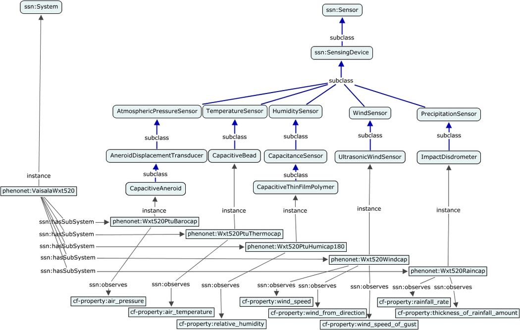
Figure 5.39 - Agriculture meteorology example: weather station
Sensor view
The definition of the UltrasonicWindSensor presented in Figure 5.40 is sourced from the Automatic Weather Station ontology (aws.xml). In the example below, the UltrasonicWindSensor class is defined as a Sensor which observes SpeedOrVelocity (wind speed) or Angle (wind direction). In this approach where the sensor classes definitions use the generic quantities from the QU ontologies and not the domain-specific properties defined in the CF ontologies. This solution based on generic dimensions has been preferred because:
- in many cases, the only information available about the type of a sensor is the unit of measurement used for its outputs,
- it separates the class definitions from the instances definitions (in ssn-phenonet.xml)
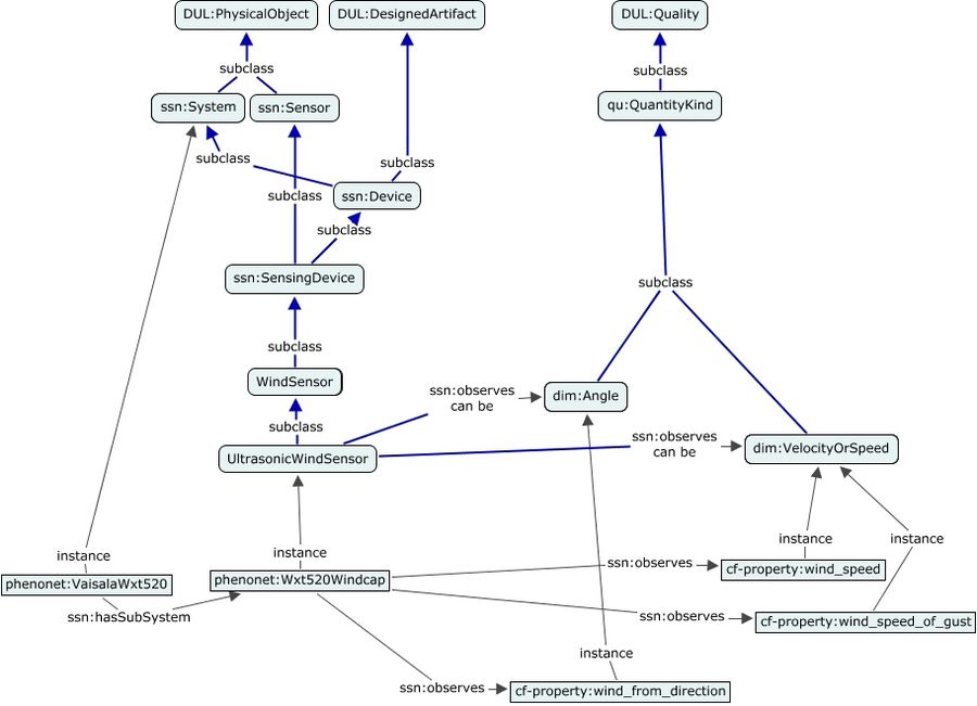
Figure 5.40 - Agriculture meteorology example: ultrasonic wind sensor
Figure 5.41 shows how the Process class is refined to model the specification of a sensor as something which produces outputs. The types of variables and their units are required to enable the generation of software modules used to program the sensor network. The same information may also be attached to the SensorOutput but only after the data has been collected (through an Observation Result).
Figure 5.41 - Agriculture meteorology example: wind sensing process
External ontologies
Automatic Weather Station ontology
The sensor taxonomy for the Agriculture Meterology domain is brought by the Automatic Weather Station ontology (aws.xml). Figure 5.42 below shows a subset of the class hierarchy defined by this ontology for the different types of sensors used in Agriculture Meteorology: Radiation, Temperature, Atmospheric pressure, Wind, Humidity and Precipitation measurements.
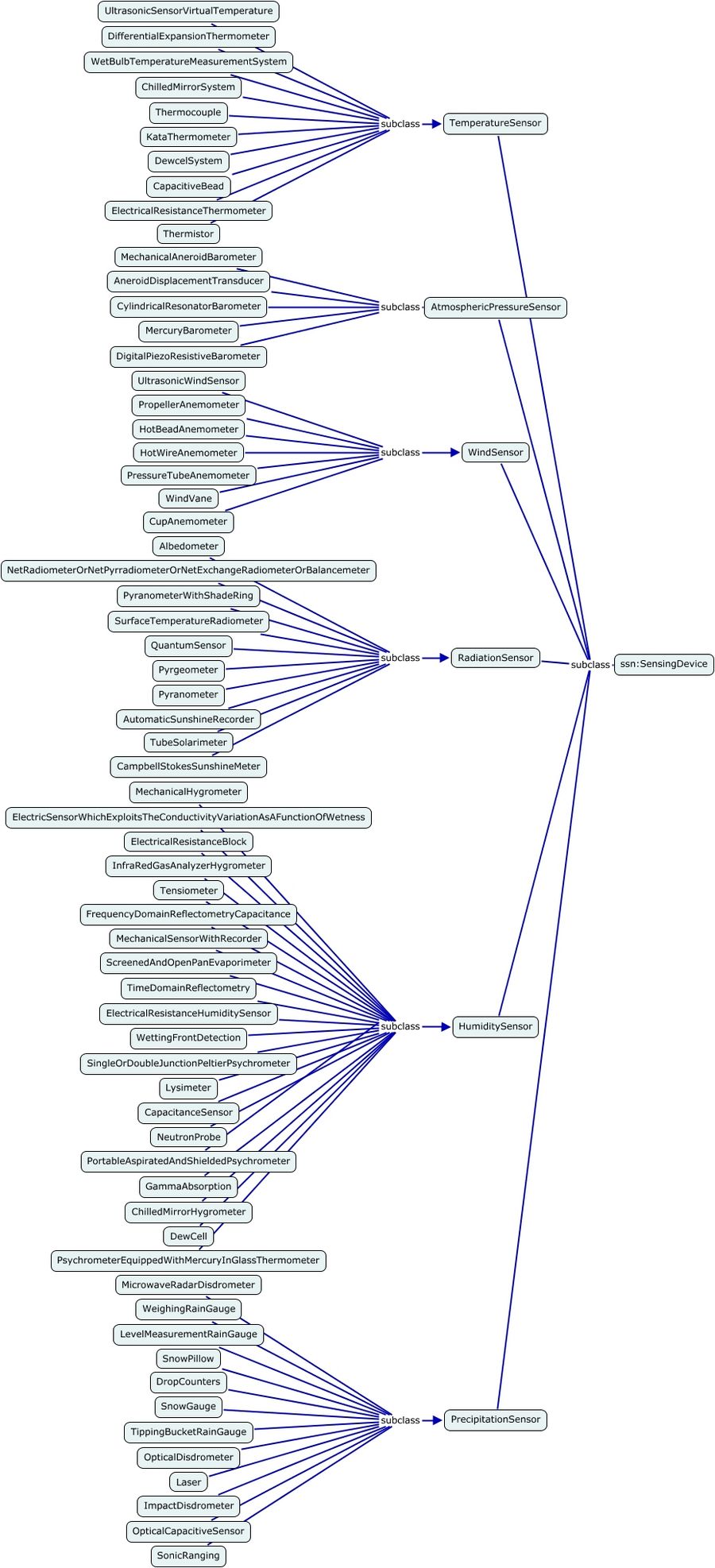
Figure 5.42 - Agriculture meteorology example: AWS ontology
The Automatic Weather Station ontology is mainly based on the technical literature published by the World Meteorological Organisation (WMO).
Additional information:
Amongst other things, it reuses the outputs of the June 2010 meeting by WMO working group on Automatic Weather Stations:
Especially the content of these two documents:
- WMO AWS Metadata catalogue or pdf version available via [1] proposed extensions of the list of sensors types
- BUFR Descriptors Related to AWS (Doc. 10.1) list of variables for each category of measurement (also hydro and marine observations e.g. discharge) with definitions which are mappable to CF
These definitions are a follow-up of earlier work done at WMO and elsewhere. Here are some extra references which provides some extra information on the Agriculture Meteorology domain and on specific sensor categories:
- WMO Guide to Agricultural Meteorological Practices (GAMP) Draft 3rd Edition (WMO-No.134) (chapter 2)
- Darnhofer Meteorological elements and their observations
- Charlesworth Soil Water Monitoring, Irrigation Insights 2nd edition
- WMO Field Intercomparison of Rainfall Intensity (RI) Gauges
- WMO CIMO Guide (extract on Pressure sensors)
CF (Climate and Forecast) ontologies
The Automatic Weather Station ontology relies on domain-specific definitions sourced from the Climate and Forecast Metadata Conventions , which includes a collection of standard names for climatic data variables. Jonathan Gregory, one of the curators of this vocabulary, has published a CF grammar which aims at a "comprehensive and systematic description of the existing names". This work has been leveraged here to identify the core feature types and instances sourced used by the CF community, which are presented in Figure 5.43.
Figure 5.43 - Agriculture meteorology example: CF features
Figure 5.44 shows how ssn:hasProperty is used to link the CF features to the CF properties and how CF properties are defined as instance of the quantity classes defined in the QU ontologies. This linkage was an important criterion in the choice of a unit of measurement and quantity ontology (see discussion below).
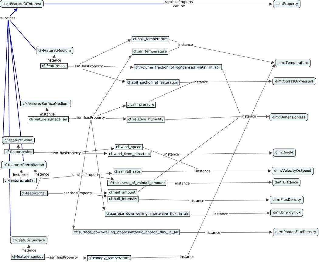
Figure 5.44 - Agriculture meteorology example: CF properties
Units of measurement and quantity ontologies
The QU and QU-Rec20 ontologies apply the QUDV specification issued by the SysML 1.2 Revision Task Force (RTF). The instance data is derived from a range of resources (see QU Rec 20 for a complete list), including the UN/CEFACT Recommendation 20 which is a list of codes for international commerce.
Figure 5.45 shows how the quantities and unit of measurement are managed in the QU and QU-Rec20 ontologies. For each dimension (Length, Mass, SpeedOrVelocity, Pressure, ...), two classes are defined, one for the quantity kind and one for the unit. The figure shows how additional quantities can be defined as instances and linked using the generalization property to the root quantity. A single "base" unit of measurement is defined for each dimension and is used as the reference for the conversion of the other available units belonging to the same dimensional category.
Figure 5.45 - Agriculture meteorology example: quantity and unit of measurement
Additional information:
We could also have used:
- QUDT developed by the Nexiom project (NASA, TopQuadrant): QUDT - Quantities, Units, Dimensions and Data Types in OWL and XML
- or Ontology of units of Measure (OM): om-1.6 developed by a team of researchers at Wageningen UR (wurvoc.org)
According to Hans Peter de Koning, QUDV and QUDT are both being considered as input for the work by OASIS on a Quantities and Units of Measure Ontology Standard (QUOMOS) which was not available at the time this example was developed.